Week-6 Challenge: EV Drivetrain
EV Drivetrain
Objectives :
1. Which types of power converter circuits are employed in electric and hybrid electric vehicle?
2. An Electric Vehicle's powertrain with 72V battery pack in shown in the diagram below. The duty ratio for acceleration operation is 'd1' and for the braking operation the duty ratio is 'd2'.
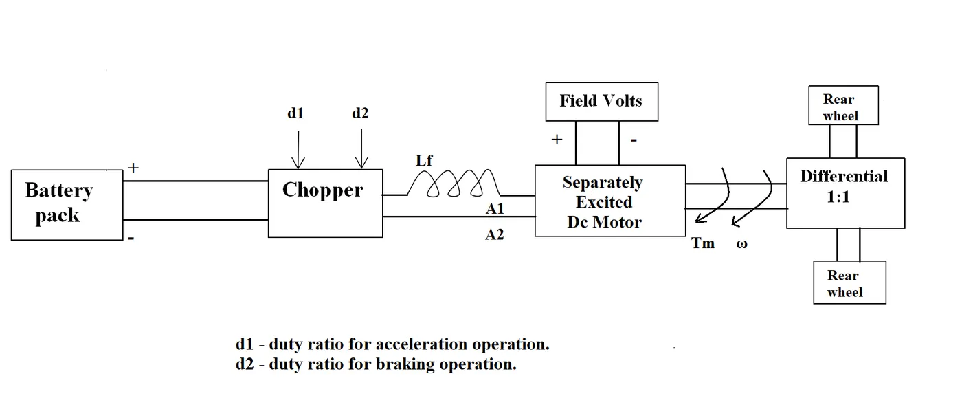
The other parameters of the electric vehicle is given below,
Motor and Controller Parameters:
Rated Armature voltage= 72 V
Rated armature current= 400 A
Ra= 0.5Ω, KΦ= 0.7 Volt second
Chopper Switching frequency= 400 Hz
The vehicle speed-torque characteristics are given by the below equation

What is EV steady state speed if duty cycle is 70%?
3. Develop a mathematical model of a DC Motor for the below equation using Simulink.
ωω= V/Kϕϕ -Ra/Kϕϕ^2 .T
4. Refer to the blog on below topic:
Induction Versus DC brushless motors by Wally Rippel, Tesla
Explain in brief about author’s perspective.
OBJECTIVES 1 :
Power Electronic Converters:
- The main aim of the converter is to produce conditioning power with respect to a certain application.
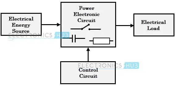
- The block diagram of a power electronic converter is shown in the figure above. It consists of an electrical energy source, a power electronic circuit, a control circuit, and an electric load. This converter changes one form of electrical energy to other forms of electrical energy.
- Power electronic converters perform various basic power conversion functions. This converter is a single power conversion stage that can perform any of the functions in AC and DC power conversion systems.
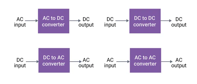
Depending on the type of function performed, power electronic converters are categorized into the following types.
- AC-to-DC= Rectifier: It converts AC to unipolar (DC) current.
- DC-to-AC= Inverter: It converts DC to AC of desired frequency and voltage.
- DC-to-DC= Chopper: It converts constant to variable DC or variable DC to constant DC.
- AC-to-AC= Cycloconverter, Matrix converter: It converts AC of the desired frequency and/or desired voltage magnitude from a line AC supply.
AC-DC converter
PHEVs and EVs are arranged also with an AC-DC converter which supplies electric power from a commercial power system to an onboard high-voltage battery. The AC-DC converter is essential to work more proficiently to cut the charging time and also to be reduced so as to be fitted in a limited space. The problems lie in large and heavy coil parts and large power loss accompanied by high-frequency switching. The AC/DC converter consists of a power factor correction (PFC) which converts input AC voltage into DC voltage, an H-bridge circuit which converts the DC voltage into high-frequency AC voltage, a high-frequency transformer which regulates transformation and insulation, and a circuit which rectifies and smooths high-frequency AC voltage. The problem with AC/DC converter is that it includes big power loss in high-frequency switching. While the increase of switching frequency can decrease the volume of coil parts, power loss by the power device increases.
DC-AC converter
The DC-AC converter (inverter) comprises six bidirectional semiconductors (IGBT). The main source of electrical power is the battery which is a DC source. The DC output of the battery is bucked or boosted according to the requirement and then converted into AC using a DC-AC inverter. The function of an inverter is to change a dc input voltage to asymmetric ac output voltage of desired magnitude and frequency. The output voltage waveforms of ideal inverters should be sinusoidal.
DC-DC converter
Usually, AC motors are used in HEVs or EVs for traction and they are fed by inverter and this inverter is fed by a DC-DC converter. The most commonly DC-DC converters used in an HEV or an EV are:
- Unidirectional Converters: They provide to several onboard loads such as sensors, controls, entertainment, utility and safety types of equipment.
- Bidirectional Converters: They are used in places where battery charging and regenerative braking is required. The power flow in a bi-directional converter is usually from a low voltage end such as a battery or a supercapacitor to a high voltage side and is referred to as boost operation.
The DC-DC converter and the boost DC-DC converter with resonant circuit is more suitable for low-power BEVs and PHEVs because of their soft switching, noise-free operation, low switching loss and high efficiency. a specific DC-DC converter to be integrated into the high voltage (HV) DC link of the powertrain. For bidirectional electric sources like SCs and batteries, bidirectional DC-DC converters are essential to absorb the regenerative braking energy, which maximizes the overall efficiency of the system. The DC-DC converters utilized in BEV and PHEV powertrains primarily use Si-based semiconductors which limits their efficiency to 92–93%, allows a maximum switching frequency up to 30 kHz and attains only 3–12 W/in3 power density.
Different DC-DC converter used in BEVs and PHEVs are
- Boost DC-DC converter (BC)
- Interleaved 4-Phase Boost DC-DC converter (IBC)
- Boost DC-DC Converter with Resonant circuit (BCRC)
- Full bridge Boost DC-DC converter (FBC)
- Isolated ZVS DC-DC converters (ZVSC)
- Sinusoidal Amplitude HV DC bus converter (SAHVC)
- Multiport isolated DC-DC converter (MPC)
- Multi-device Interleaved Bidirectional DC-DC converter (MDIBC).
AC-AC converter
A solid-state AC-to-AC converter converts an AC waveform to another AC waveform, where the output voltage and frequency can be set randomly. This change is mainly essential in case of speed controlling of machines, for low frequency and variable voltage magnitude applications as well. We know that there are different types of loads that work with different types of power supplies like single-phase, three-phase supply, and the supplies can be differentiated based on the voltage and frequency range also.
The AC to AC converters can be classified into different types:
- Cycl converters
- AC to AC Converters with DC link
- Matrix Converters
- Hybrid Matrix Converters
OBJECTIVE 2 :
parameters of the electric vehicle is given below,
Motor and Controller Parameters:
Rated Armature voltage= 72 V
Rated armature current= 400 A
Ra= 0.5Ω
Motor constanr KΦ= 0.7 Volt second
Chopper Switching frequency= 400 Hz
Calculation:
For 70% Duty cycle,
= 72 * 70 / 100
= 5040/100
= 50.4 volts (Now, Using the value in eq. (i)
Now,
The DC machine torque speed is calculated by using
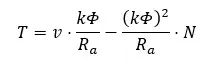 ………………………………(i)
Where
T = Torque
V = Voltage
N = Motor speed (ω)
Ra = Armature Resistance
K = Motor Constant
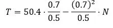
T = 70.56 – 0.98 * N
T = 70.56 – 0.98 * ω
Now,
24.7+0.0051 ω2 = 70.56 – 0.98 * ω
0.0051 ω2 + 0.98 ω - 45.89 = 0 (By Equating both the expression)
For solving the quadratic equation, we have to use the given equation
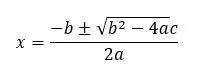
x = (-0.98± (0.0051) (-45.89)) / (2* 0.0051)
x = (-0.98± 1.377) / 0.0102……………………...(ii)
If we add in eq (ii) we get,
x = - 2.357/0.0102
x = - 231.07
If we subtract in eq (ii) we get,
x = 0.397/0.0102
x = 38.91
Thus, we get, Angular speed: ω = -231.07 rad/s & 38.91 rad/s
At 70% duty cycle the 38.91 rad/s or -231.07 rad/s will be EV steady state speed.
OBJECTIVE 3 :
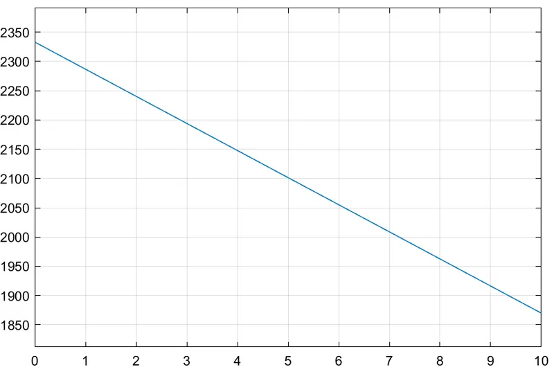
a mathematical model of a DC Motor for the below equation using Simulink.
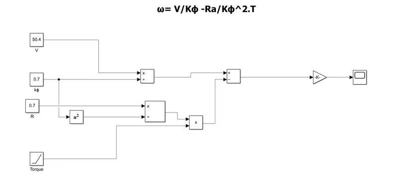
Blocks used
- 3 Constant block (for Voltage, motor constant and resistance)
- 1 Ramp block (for torque)
- 3 divide block
- 1 square block
- 1 product block
- 1 Gain block
- 1 Scope block
OUTPUT :
OBJECTIVE 4 :
DC brushless drives:
- In brushless machines, the rotor includes two or more permanent magnets that generate a DC magnetic field (as seen from the vantage point of the rotor). In turn, this magnetic field enters the stator core (a core made up of thin, stacked laminations) and interacts with currents flowing within the windings to produce a torque interaction between the rotor and stator. As the rotor rotates, it is necessary that the magnitude and polarity of the stator currents be continuously varied – and in just the right way - such that the torque remains constant and the conversion of electrical to mechanical energy is optimally efficient.
- The device that provides this current control is called an inverter. Without it, brushless motors are useless motors.
- A brushless DC motor produces no starting torque when directly connected to fixed frequency utility power. They really need the aid of an inverter whose “phase” is maintained in step with the angular position of the rotor.
- One of the main differences is that much less rotor heat is generated with the DC brushless drive.
- Rotor cooling is easier and peak point efficiency is generally higher for this drive.
- In an ideal brushless drive, the strength of the magnetic field produced by the permanent magnets would be adjustable.
- DC brushless drives require an absolute position sensor.
Induction motor drives:
- The induction rotor has no magnets – just stacked steel laminations with buried peripheral conductors that form a “shorted structure.” Currents flowing in the stator windings produce a rotating magnetic field that enters the rotor.
- In turn, the frequency of this magnetic field as “seen” by the rotor is equal to the difference between the applied electrical frequency and the rotational “frequency” of the rotor itself. Accordingly, an induced voltage exists across the shorted structure that is proportionate to this speed difference between the rotor and electrical frequency. In response to this voltage, currents are produced within the rotor conductors that are approximately proportionate to the voltage, hence the speed difference. Finally, these currents interact with the original magnetic field to produce forces – a component of which is the desired rotor torque.
- The fact that induction motors are directly compatible with conventional utility power is the main reason for their success.
- When a 3-phase induction motor is connected to utility type 3-phase power, torque is produced at the outset. The motor has the ability to start under load. No inverter is needed.
- In contrast, induction machines have no magnets, and B fields are adjustable.
- Induction drives require only a speed sensor.
Similarities of Induction And DC brushless drives:
- Both DC brushless and induction drives use motors having similar stators.
- Both drives use 3-phase modulating inverters. The only differences are the rotors and the inverter controls. Moreover, with digital controllers, the only control differences are with the control code.
Conclusion:
- We conclude that DC brushless drives will likely continue to dominate in the hybrid and coming plug-in hybrid markets, and that induction drives will likely maintain dominance for the high-performance pure electrics.
- The fact that so much of the hardware is common for both drives could mean that we will see induction and DC brushless life and work side by side during the coming golden era of hybrid and electric vehicles.