Week-6 Challenge: EV Drivetrain
AIM: To have a detailed study on power converters and their application in EV and HEV.
objective:
Study 1:
Which types of power converter circuits are employed in electric and hybrid electric vehicle?
Ans:
A power converter is an electrical circuit that changes the electric energy from one form into the desired form optimized for the specific load. A converter may do one or more functions and give an output that differs from the input. It is used to increase or decrease the magnitude of the input voltage, invert polarity, or produce several output voltages of either the same polarity with the input, different polarity, or mixed polarities such as in the computer power supply unit.
The DC-to-DC converters are used in a wide range of applications including computer power supplies, board level power conversion and regulation, dc motor control circuits and much more.
The converter acts as the link or the transforming stage between the power source and the power supply output. There are several kings of converters based on the source input voltage and the output voltage and these falls into four categories namely the AC to DC converter known as the rectifier, the AC-to-AC cycloconverter or frequency changer, the DC-to-DC voltage or current converter, and the DC to AC inverter.
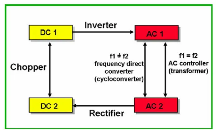
Charging an EV or PHEV need to have a power converter which converts AC voltage to DC voltage, we need a chopper to connect battery and Dc machine, and we need an inverter to connect battery and AC motor, for recharging the battery we need a conversion between AC and DC here we use Rectifier.
Study 2:
Ans:
Given:
Motor and Controller Parameters:
Rated Armature voltage= 72 V
Rated armature current= 400 A
Ra= 0.5Ω, KΦ= 0.7 Volt second
Chopper Switching frequency= 400 Hz
The vehicle speed-torque characteristics are given by the below equation
 (For vehicle )
What is EV steady state speed if duty cycle is 70%
Differential Gear ratio = 1:1
Tm = ((V * k`phi`)/Ra - (k`phi`)^2 / Ra) * w
Voltage at Motor = Vm
Vm = 0.7 * V
= 0.7 * 72
= 50.4Volts
Now, torque at motor ;
Tm = ((V * k`phi`)/Ra - (k`phi`)^2 / Ra) * w
= ((50.4*0.7)/0.5 - ((0.7)^2)/0.5)) * w
Tm = 70.56 - 0.98w
As gear ratio is = 1, Then torque at motor is equal to torque at wheel so,
Tm = Tv
0.0051w^2 - 0.98Wm - 45.86= 0
w = 39 rad/sec
Study 3:
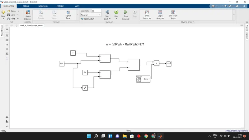
Develop a mathematical model of a DC Motor for the below equation using Simulink.
ω= V/Kϕ -Ra/Kϕ^2 . T
Ans:
Simulink Block Arrangement:
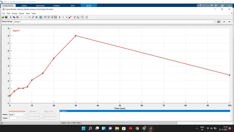
Input Signal Variation:
Variables From workspace:

Results:
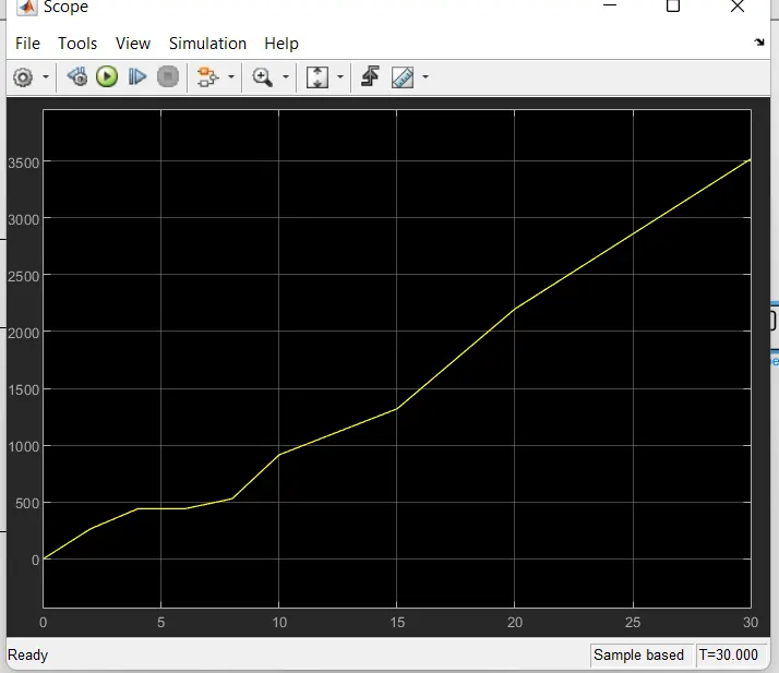
Above graph resembles a linear trend in comparison with the input signal.
Study 4:
Refer to the blog on below topic:
Induction Versus DC brushless motors by Wally Rippel, Tesla
Explain in brief about author’s perspective.
Ans:
Author just stated working principles and advantages and disadvantages for both induction and dc brushless motors, they are mentioned below:
Construction of Dc brushless motor:
the rotor includes two or more permanent magnets that generate a DC magnetic field (as seen from the vantage point of the rotor). In turn, this magnetic field enters the stator core (a core made up of thin, stacked laminations) and interacts with currents flowing within the windings to produce a torque interaction between the rotor and stator.
Advantages of DC brushless motors:
1.much less rotor heat is generated with the DC brushless drive.
2.Rotor cooling is easier and peak point efficiency is generally higher for this drive.
3.The DC brushless drive can also operate at unity power factor.
4.This means that the peak point energy efficiency for a DC brushless drive will typically be a few percentage points higher than for an induction drive.
Construction of Induction motor:
Unlike the DC brushless rotor, the induction rotor has no magnets – just stacked steel laminations with buried peripheral conductors that form a “shorted structure.” Currents flowing in the stator windings produce a rotating magnetic field that enters the rotor. In turn, the frequency of this magnetic field as “seen” by the rotor is equal to the difference between the applied electrical frequency and the rotational “frequency” of the rotor itself
Advantages of induction motor:
1.induction machines have no magnets and B fields are “adjustable,” since B is proportionate to V/f (voltage to frequency). This means that at light loads the inverter can reduce voltage such that magnetic losses are reduced and efficiency is maximized.
2.This advantage becomes increasingly important as performance is increased.
3.With induction, as machine size grows, losses do not necessarily grow. Thus, induction drives may be the favored approach where high-performance is desired; peak efficiency will be a little less than with DC brushless, but average efficiency may actually be better.
Conclusion:
1.Both have their own set of advantages and disadvantages, when it comes to best efficiency BLDM comes first but for avg efficiency Induction motor comes first.
1.My conclusion is that DC brushless drives will likely continue to dominate in the hybrid and coming plug-in hybrid markets, and that induction drives will likely maintain dominance for the high-performance pure electrics.