Week-6 Challenge: EV Drivetrain
AIM:
Objective:
1. Which types of power converter circuits are employed in electric and hybrid electric vehicle?
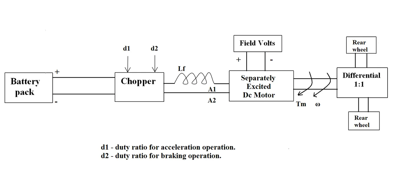
2. An Electric Vehicle's powertrain with 72V battery pack in shown in the diagram below. The duty ratio for acceleration operation is 'd1' and for the braking operation the duty ratio is 'd2'.
The other parameters of the electric vehicle is given below,
Motor and Controller Parameters:
Rated Armature voltage= 72 V
Rated armature current= 400 A
Ra= 0.5Ω, KΦ= 0.7 Volt second
Chopper Switching frequency= 400 Hz
The vehicle speed-torque characteristics are given by the below equation

What is EV steady state speed if duty cycle is 70%?
3. Develop a mathematical model of a DC Motor for the below equation using Simulink.
ω">ωω= V/Kϕ">ϕϕ -Ra/Kϕ">ϕϕ^2 .T
4. Explain in brief about author’s perspective.
Solution1:
POWER ELECTRONIC CONVERTERS:
• Power electronic converters are used everywhere in normal daily routines at home, commercial workplaces or in an industrial environment.
• Power electronic technology deals with processing and controlling the flow of electrical energy in order to supply voltages and currents in a form that optimally suited for end user’s requirements.
• A power electronic converter uses power electonic components such as SCRs, TRIACs, IGBTs, etc. to control and convert the electric power. The main aim of the converter is to produce conditioning power with respect to a certain application.
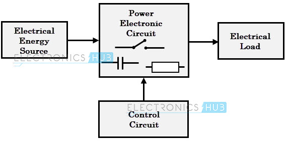
• The block diagram of a power electronic converter is shown in figure above. It consist of an electrical energy source, power electronic circuit, a control circuit and an electric load. This converter changes one form of electrical energy to other form of electrical energy.
• The power electronic circuit consists of both power part and control part. Power part transfers the energy from source to load and it consists of power electronic switches (SCR or TRIAC), transformers, electric choke, capacitors, fuses and sometimes resistors.
• The control circuit or block regulates the elements in the power part of the converter. This block is built with a complex low power electronic circuit that consists of either analog or digital circuit assembly.
• Power electronic converters perform various basic power conversion functions. This converter is a single power conversion stage that can perform any of the functions in AC and DC power conversion systems.
Depending on the type of function performed, power electronic converters are categorized into following types.
- AC to DC ( Rectifier) It converts AC to unipolar (DC) current
- DC to AC ( Inverter) It converts DC to AC of desired frequency and voltage
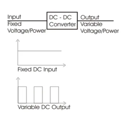
- DC to DC ( Chopper) It converts constant to variable DC or variable DC to constant DC
- AC to AC ( Cycloconverter) It converts AC of desired frequency and/or desired voltage magnitude from a line AC supply.
AC to DC (Rectifier):
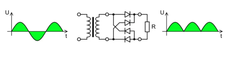
• A rectifier is an electrical device that converts alternating current (AC), which periodically reverses direction, to direct current (DC), which flows in only one direction. The reverse operation is performed by the inverter.
• The process is known as rectification, since it "straightens" the direction of current, Physically, rectifiers take a number of forms, including vacuum tube diodes, wet chemical cells, mercury-arc valves, stacks of copper and selenium oxide plates, semiconductor diodes, silicon- controlled rectifiers and other silicon-based semiconductor switches. Historically, even synchronous electromechanical switches and motors have been used. Early radio receivers, called crystal radios, used a cat's whisker" of fine wire pressing on a crystal of galena (lead sulfide) to serve as a point-contact rectifier or "crystal detector"
• Rectifiers have many uses, but are often found serving as components of DC power supplies and high-voltage direct current power transmission systems. Rectification may serve in roles other than to generate direct current for use as a source of power. As noted, detectors of radio signals serve as rectifiers. In gas heating systems flame rectification is used to detect presence of a flame.
• Depending on the type of alternating current supply and the arrangement of the rectifier circuit, the output voltage may require additional smoothing to produce a uniform steady voltage. Many applications of rectifiers, such as power supplies for radio, television and computer equipment, require a steady constant DC voltage (as would be produced by a battery). In these applications the output of the rectifier is smoothed by an electronic filter, which may be a capacitor, choke, or set of capacitors, chokes and resistors, possibly followed by a voltage regulator to produce a steady voltage.
DC to AC (Inverter):
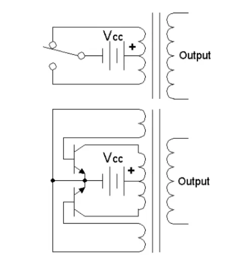
• A power inverter, or inverter, is a power electronic device or circuitry that changes direct current (DC) to alternating current (AC). The resulting AC frequency obtained depends on the particular device employed. Inverters do the opposite of "converters" which were onginally large electromechanical devices converting AC to DC
• The input voltage, output voltage and frequency, and overall power handling depend on the design of the specific device or circuitry. The inverter does not produce any power, the power is provided by the DC source.
• A power inverter can be entirely electronic or may be a combination of mechanical effects (such as a rotary apparatus) and electronic circuitry Static inverters do not use moving parts in the conversion process.
• Power inverters are primarily used in electrical power applications where high currents and voltages are present circuits that perform the same function for electronic signals, which usually have very low currents and voltages, are called oscillators.
DC to DC( Chopper):
• In electronics, a chopper circuit is used to refer to numerous types of electronic switching devices and circuits used in power control and signal applications. A chopper is a device that converts fixed DC input to a variable DC output voltage directly. Essentially, a chopper is an electronic switch that is used to interrupt one signal under the control of another.
• In power electronics applications, since the switching element is either fully on or fully off, its losses are low and the circuit can provide high efficiency. However, the current supplied to the load is discontinuous and may require smoothing or a high switching frequency to avoid undesirable effects.
• In signal processing circuits, use of a chopper stabilizes a system against drift of electronic components; the original signal can be recovered after amplification or other processing by a synchronous demodulator that essentially un-does the "chopping" process
AC to AC (Regulator):
• A voltage regulator is a system designed to automatically maintain a constant voltage level A voltage regulator may use a simple feed- forward design or may include negative feedback. It may use an electromechanical mechanism, or electronic components. Depending on the design, it may be used to regulate one or more AC or DC voltages.
• Electronic voltage regulators are found in devices such as computer power supplies where they stabilize the DC voltages used by the processor and other elements.
• In automobile alternators and central power station generator plants, voltage regulators control the output of the plant. In an electric power distribution system, voltage regulators may be installed at a substation or along distribution lines so that all customers receive steady voltage independent of how much power is drawn from the line.
Electric Vehicles:
An electric vehicle (EV) is a vehicle that uses one or more electric motors or traction motors for propulsion. An electric vehicle may be powered through a collector system by electricity from off-vehicle sources, or may be self-contained with a battery, solar panels, fuel cells or an electric generator to convert fuel to electricity.
Hybrid Electric Vehicles:
A hybrid electric vehicle (HEV) is a type of hybrid vehicles that combines a conventional internal combustion engine (ICE) system with an electric propulsion system. The presence of the electric powertrain is intended to achieve either better fuel economy than a conventional vehicle or better performance. There is a variety of HEV types and the degree to which each function as an electric vehicle (EV) also varies. The most common form of HEV is the hybrid electric car, although hybrid electric trucks (pickups and tractors), buses, boats and aircraft also exist.
Power converters circuits for electric and hybrid electric vehicles:
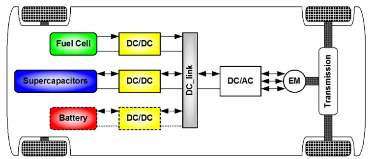
The different configurations of EV power supply show that at least one DC/DC converter is necessary to interface the FC, the Battery or the Supercapacitors module to the DC-link.DC/DC converters can be designed to transfer power in only one direction, from the input to the output. However, almost all DC/DC converter topologies can be made bi-directional. A bi-directional converter can move power in either direction, which is useful in applications requiring regenerative braking.
The most common DC/DC converters can be grouped as follows:
Non-isolated converters
The non-isolated converters type is generally used where the voltage needs to be stepped up or down by a relatively small ratio (less than 4:1). And when there is no problem with the output and input having no dielectric isolation. There are five main types of converter in this non- isolated group. usually called the buck, boost, buck-boost. Cuk and charge-pump converters. The buck converter is used for voltage step-down, while the boost converter is used for voltage step-up. The buck-boost and Cuk converters can be used for either step-down or step-up. The charge-pump converter is used for either voltage step-up or voltage inversion, but only in relatively low power applications.
Isolated converters
Usually, in this type of converters a high frequency transformer is used. In the applications where the output needs to be completely isolated from the input, an isolated converter is necessary. There are many types of converters in this group such as Half-Bridge, Full-Bridge, Fly-back, Forward and Push-Pull DC/DC converters. All of these converters can be used as bi-directional converters and the ratio of stepping down or stepping up the voltage is high.
Non-isolated converters:
Buck-A buck converter (step-down converter) is a DC to DC power converter which steps down voltage from its input (supply) to its output (load). It is a class of switched mode power supply (SMPS) typically containing at least two semiconductors a diode and a transistor, although modern buck converters frequently replace the diode with a second transistor used for synchronous rectification and at least one energy storage element, a capacitor.inductor, or the two in combination. To reduce voltage ripple, filters made of capacitors (sometimes in combination with inductors) are normally added to such a converter's output (load-side filter) and input (supply-side filter).
solution 2:
An Electric Vehicle's powertrain with 72V battery pack in shown in the diagram below. The duty ratio for acceleration operation is 'd1' and for the braking operation the duty ratio is 'd2'.
Given :
Rated Armature voltage= 72 V
Rated armature current= 400 A
Ra= 0.5Ω, KΦ= 0.7 Volt second
Chopper Switching frequency= 400 Hz
Speed-Torque equation of motor
`omega=V(K Phi)-R_a/(K Phi)^2*`T_m`
For the value of V we need multiply the Armature voltage with duty cycle -
therefore,
`V=72*(70/100)=50.4 text(Volts)`
By substitute the value in Speed-Torque equation of motor we get,
`T_m=70.56-0.98omega`
We have been given that Vehicle Speed Torque Characteristics as,
`T_m=24.7+0.0051w^2`
Where,
`T_v=`Torque of the Vehicle
At Steady State,
`T_v=T_m`
By substituting the equation we get,
`24.7+0.0051omega^2=70.56-0.98omega`
On solving this equation we get the value of `omega` as
`omega=32.98, omega=-231.07`
We are considering positive value of `omega` as we have taken it has forword motion.
Solution3: Develop a mathematical model of a DC Motor for the below equation using Simulink.
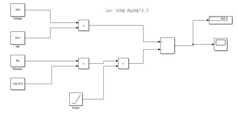
ω = (V/Kϕ) -Ra/(Kϕ)^2 .T
Model for the above equation
Result:
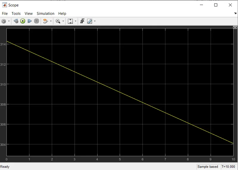
This result shows torque speed curve for DC motor
Solution4: Explain in brief about author’s perspective.
Induction Versus DC brushless motors by Wally Rippel, Tesla
This blog is about the Walley Reppel perspective about brushless DC and induction motor, who is Walley ?
Walley is proponent of Electric Vehicle He was engineer at AeroVironment, Where is he helped to develop the EV1 for General motor He also worked in Jet propulsion laboratory on electric vehicle battery research,among other projects. Proponent means someone who is in favor of something.
In the starting of the blog he said "One Size Does Not Fit All"
he said in that odious world engines are of the different type. He said one would thought that year ago some was try to figure out which is best engine and that should be in production but his thought got failed there is no one is best one with the different requirement there are different type of engine such a way he said this true for Brushless DC and Induction Motor.
He also said about the evolution of battenes DC bush motor and contactor controllers he said the lead acid battery is replaced by the lithium and brush DC motor with Brushless DC motor or Induction motor.
Next he talks a closer look, he gives some closer look of the brushless DC motor and induction motor there technologies there working
Also he speak about what differentiate them ? in that he told about DC brushless machine that rotor generate the magnetic field with two or more permanent magnet and this magnetic field enters the stator core (a core made up of thin, stacked laminations) and interacts with currents flowing within the windings to produce a torque interaction between the rotor and stator. As the rotor rotates, it is necessary that the magnitude and polarity of the stator currents be continuously vaned-and in just the right way - such that the torque remains constant and the conversion of electrical to mechanical energy is optimally efficient. The device that provides this current control is called an inverter He told one thing that Without inverter, brushless motors are useless motors.
Then is told about the induction motor drives. he curiously told that stator of the both DC brushless and induction motor have three sets of "distributed windings" the only difference is in the rotor, induction motor has no magnet it contains steel laminations with buried peripheral conductors He descnbe working of induction motor that Currents flowing in the stator windings produce a rotating magnetic field that enters the rotor. In turn, the frequency of this magnetic field as "seen" by the rotor is equal to the difference between the applied electrical frequency and the rotational "frequency" of the rotor itself. Accordingly, an induced voltage exists across the shorted structure that is proportionate to this speed difference between the rotor and electrical frequency. In response to this voltage, currents are produced within the rotor conductors that are approximately proportionate to the voltage, hence the speed difference. Finally, these currents interact with the original magnetic field to produce forces -a component of which is the desired rotor torque.
He said that induction motor not require inverter and the motor has ability to start under the load
with the fixed utility power dc brushless motor produces no starting torque it needs inverter
induction motor not operated form the DC source Next he is talking with the heading "Brushless or Induction" He told that back 1990s all EV except one uses the DC brushless drives today all HEV using the DC brushless
Then he gave some comparison between DC brushless and induction motor
DC Brushless
1 require an absolute position sensor
2 less rotor heat is generated ,Rotor cooling is easier and peak point efficiency higher.
operate at unity power factor
3 Average efficiency is low
4 Permanent magnets are expensive
5 they are easy to control
Induction motor
1 require an absolute position sensor
2 power factor is about 85 %. efficiency high
3 Average efficiency is high
4 no magnet there is advantage in cost
5 The control laws are more complex and difficult to understand, so difficult to control
with saying "Still No Winner",he describe that no one is best DC brushless or induction.
He concluded that both are the best as per the requirement.
Conclusion:
• we explain type of power converter used HEV and EV
• using matlab code We get steady state speed for vehicle
• we create the simulink model in simulink
• we give the Explain in brief about author's perspective about DC brushless motor and induction motor