Week -2
Week -2 1 Make a Simulink model of Doorbell using solenoid block with the following details: In the above arrangement, when the switch is closed the electromagnet receives electrical power from the battery and pulls the metal arm to hit the bell producing sound. Create a situation where the switch is closed for 2 seconds and then released. Observe the physical movement of the plunger.
Assume remaining parameters.
Ans :
In the electric bell when the switch is closed the electromagnet receives the electric power from battery and pulls the metal hammer to hit the bell producing sound.
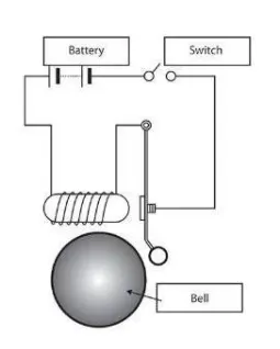
Part 1: Simulink model of Doorbell using solenoid block Model-
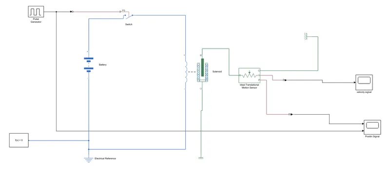
The above model uses the following blocks
1.Pulse generator
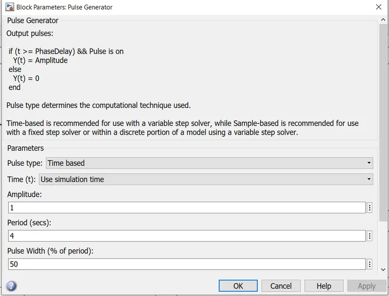
This block generates a pulse of amplitude and for a duration of 2 seconds (50% of 4 seconds). This signal is then converted to Physical Signal using the Simulink PS Converter black.
2 The Physical signal controls the switch shown below
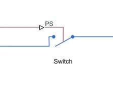
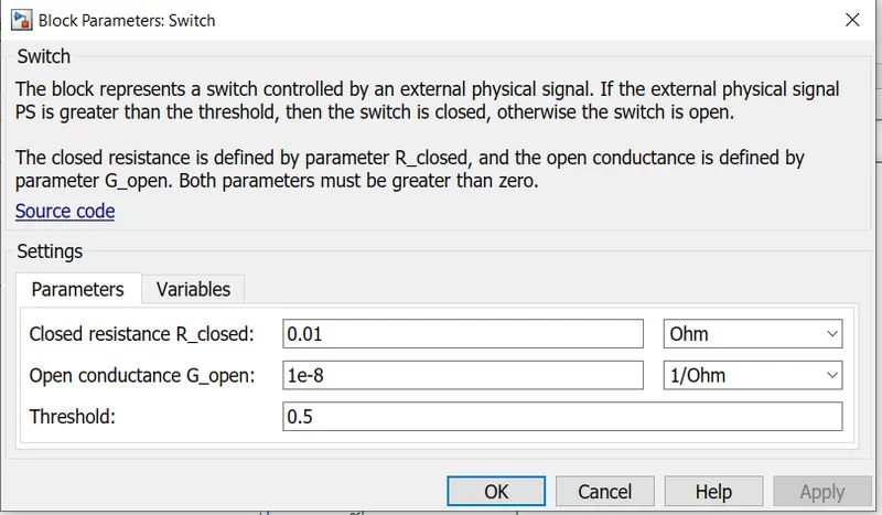
The switch remains closed if the physical signal is greater than the threshhold.
3. The blue colored circuit shown is the electrical circuit which is controlled by the switch. When the circuit is closed the current flows from the battery to the solenoid which actuates the plunger.
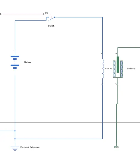
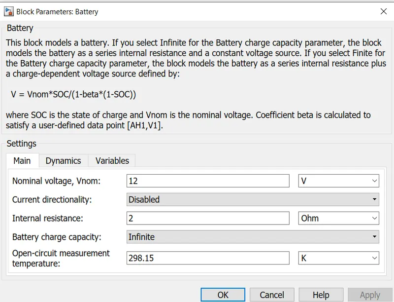
The Battery used is 12V with 2 ohms internal resistance battery
4.Doorbell mechanism
The green circuit shows the doorbell mechanis
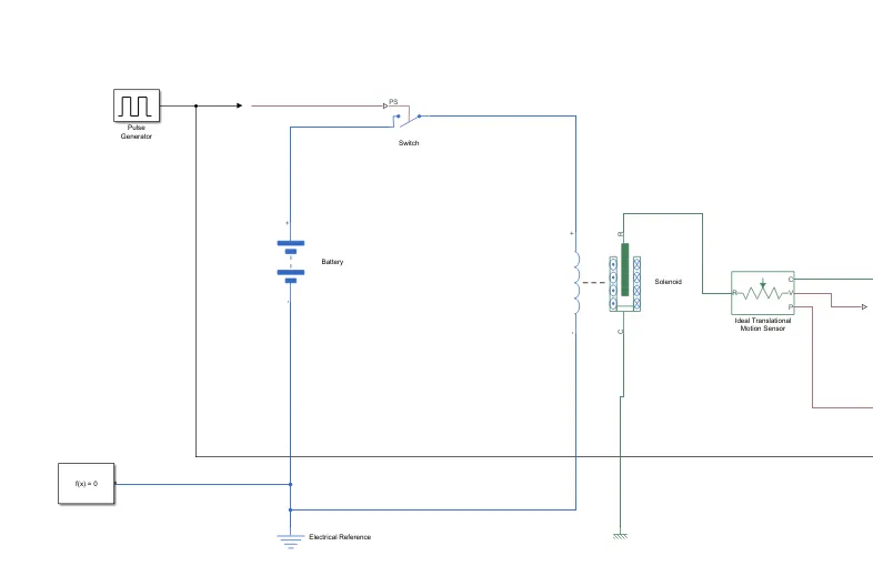
The Plunger moves when there is a current in the solenoid. The Plunger movement causes the doorbell to ring. The plunger motion is measured by a translational motion sensor which is plotted by the scope block.
5.Solenoid
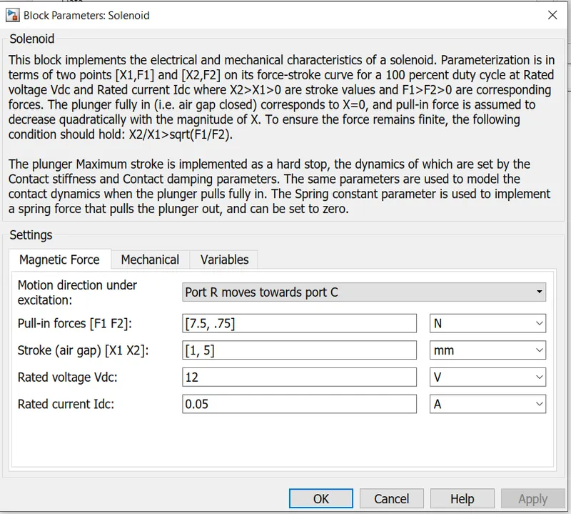
F1 and F2 are forces corresponding to X1 and X2. Rated voltage is the voltage required to power up the solenoid.
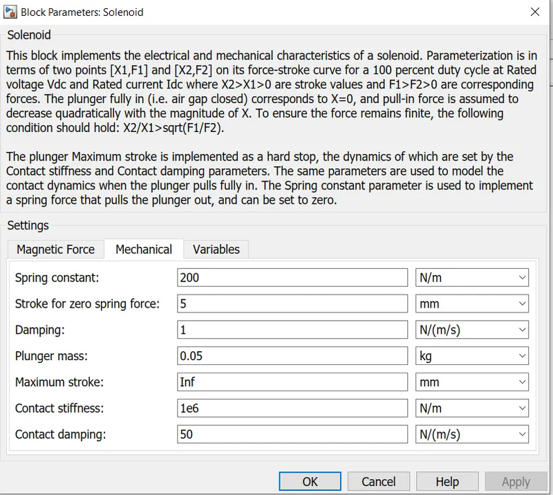
Parameter for the plunger mass, spring stiffness and damper coefficient.
6. Ideal Translational Motion Sensor:
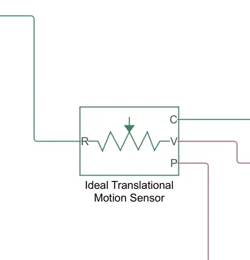
It is the motion sensor which senses the plunger motion to
plot the plunger motion versus time.
Results:
Position Signal
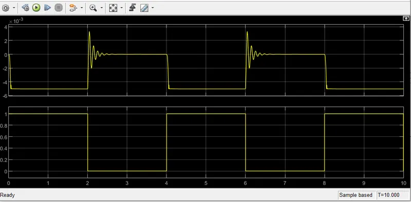
For the first 2 seconds the electrical circuit is closed and the doorbell rings. At time - 2 seconds the circuit breaks and the spning pull the plunger back to its original position. Now, because of the spring stiffness the plunger oscillated for about half-a second which is nothing but damping effect.
To minime the plunger oscillation we can increase damping coefficient of spring.
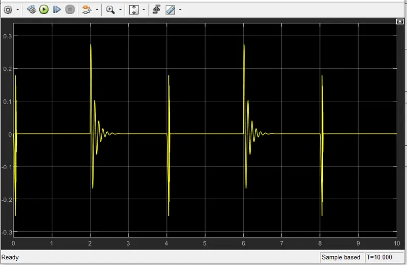
Velocity Signal
Ans:
THERMISTOR
A themistor is a resistance thermometer or a resistor whose resistance is dependent on temperature. The term s a combination af 'thermal' or 'resistor' It is made of metallic oxides, pressed into a bead. disk, or cylindical shape, and then encapsulated with an impermeable Such as epoxy or glass.
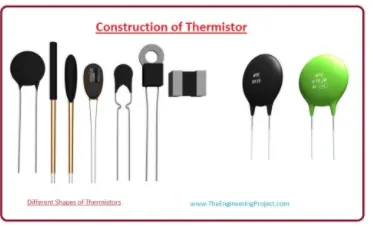
There are two types of themistors one is NTC and the second is PTC.
NTCnegative temperature coefficient) are mostly used themistors When temperature increases, resistance will be decreased. tempeut decreases, resistance will be increased.
BLOCKS ARE USED:
Signal builder: use the signal builder to create and access the signal bulder blocks.
Battery: battery is used to supply voltage to the thermistor .
Thermistor : The block represents the NTC THERMISTOR.
Resistor: The relationship between voltage and current is V=IR. Resistors have positive and negative signs. current flowing positive to negetive.
Controlled temperature source :This block represents an ideal energy source in the theRmal network that can maintain the controlled temperature ditferences regardless of heat flow rate .
Temperature source: This block represents an ideal energy source in the thermal network that can maintain constant absolute temperature regardless of heat flow rate.
Voltage sensor: ths block represents a voltage sensor its used for measuring Voltage.
Electrical reference: port connected to the ground A model must contan at least one electrical port.
switch: block s passes through one pont the second input the control input.
EXPLANATION:
SAMULINK MODEL:
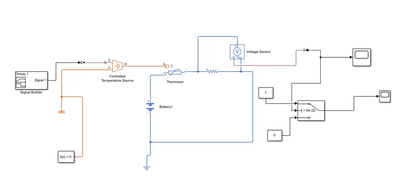
-Battery connected to the themistor.current flow through the positive signs of the resistor.
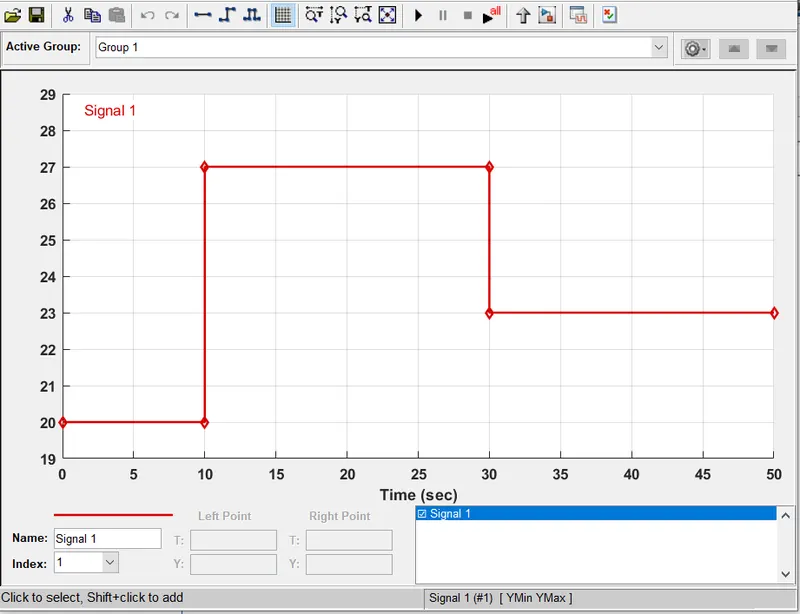
-use a signal builder to create access to the signals connected with controlled temperature.
-give inputs to signal builder based on the given inputs
Temperature source: 20 C from O to 10 seconds. 27 C from 10 to 30 seconds, 23 C from 30 to 50 seconds.
Fan conditions: ON if the temperature above 25 C OFF otherwise
•electrical reference connected wth the circuit must contain blocks.
• voltage sensor connects with a circuit to measure the voltage.
• now the switch has three ports. above threshhold voltage connect to the middle port. The other 2 pots are connected with constant blocks 1 and O switch on or off respectively.
• WE will provide the input for switch 22.5 if the condition is ON if the temperature above 25 C ,OFF
othewise
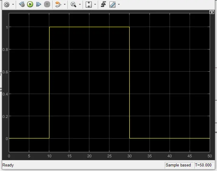
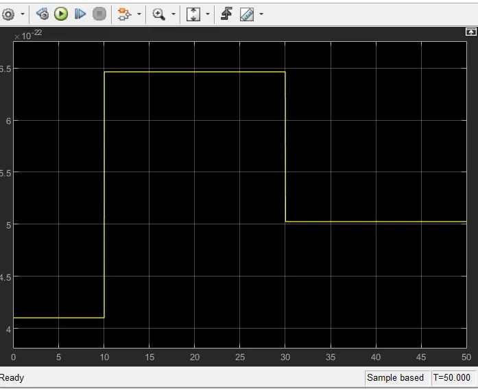
OUTPUT:Fron below graph :
Tempreture source: 20 C from O to 10 seconds switch is OFF 27 C from 10 to 30 seconds switch is ON 23 C from 30 to 50 seconds switch OFF