Week-6 Challenge: EV Drivetrain
1. Which types of power converter circuits are employed in electric and hybrid electric vehicle?
A. The power converter circuits are the elements for the interfacing of the voltage and drive train of the electric vehicle(EV)
The converter topologies are classified as Buck ,Boost and Buck-Boost.
Buck converter: The buck converter is step down converter and produces a lower average output voltage than the dc input voltage.
Boost converter: The output voltage is always greater than input voltage.
Buck-Boost converter: The output voltage can be either higher or lower than the input voltage.
The basic electrical architecture of the HEV/EV.
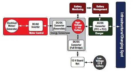
a) DC-DC Converter(Chopper):This converter is used for interfacing the elements in the power train by step-up or step-down the voltage levels.It is used in the auxiliary in the EV. A step-up converter which turns a low voltage input in to a high voltage output or a step-down converter,which does the opposite.
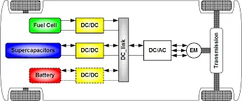
DC-DC converter for electric vehicles.
b) AC-DC Converter(Rectifier): The AC-DC Converter is used for EV Charger( Battery) in Electrical Vehicle.These types converters are we may seen at the On Board Charger/charging stations. This types converter mainly used in the Plug-in hybrid electrical vehicle(PHEV) and Plug-in Electrical Vehicle(PEV).
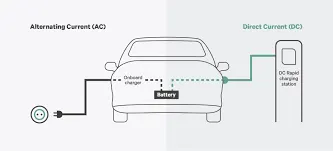
c) DC-AC Converter(Inverter):The DC-AC Converter is used for Motor Drive(increase/decreases the amplitude of the signal) .It plays a significant role in capturing energy from regenerative braking and feeding it back to the battery.
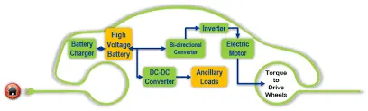
The total parts of the EV as shown below.
2.An Electric Vehicle's powertrain with 72V battery pack in shown in the diagram below. The duty ratio for acceleration operation is 'd1' and for the braking operation the duty ratio is 'd2'.
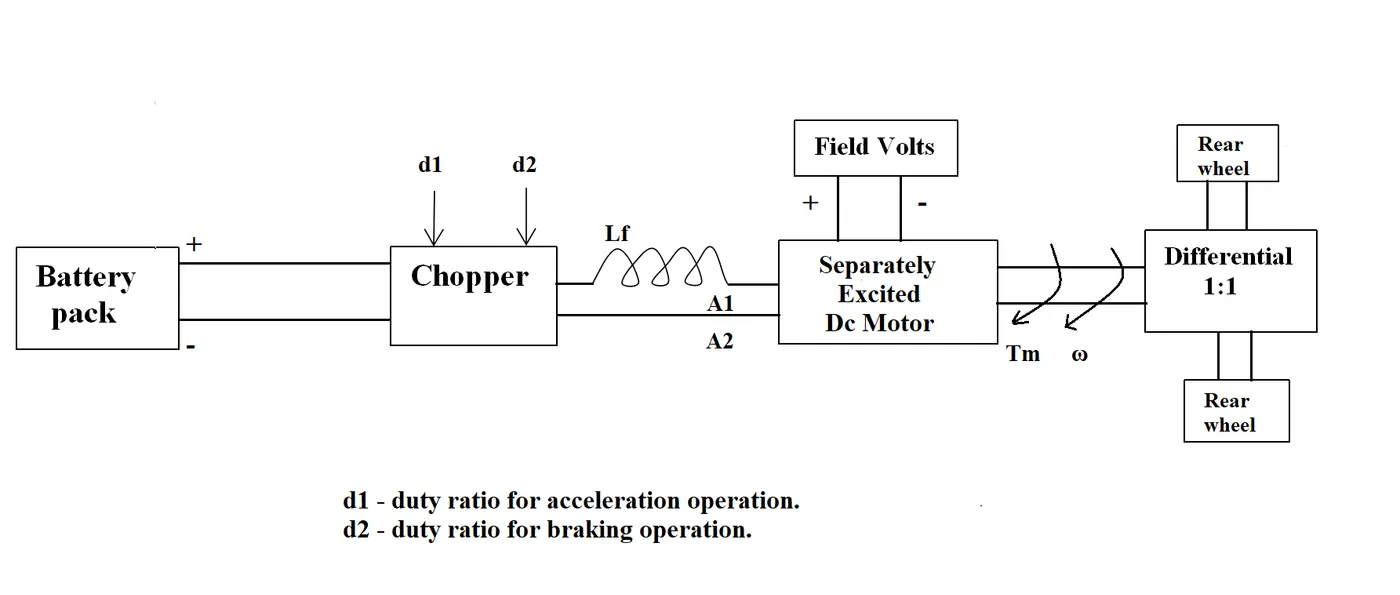
The other parameters of the electric vehicle is given below,
Motor and Controller Parameters:
Rated Armature voltage= 72 V
Rated armature current= 400 A
Ra= 0.5Ω, KΦ= 0.7 Volt second
Chopper Switching frequency= 400 Hz
The vehicle speed-torque characteristics are given by the below equation

Steady state speed of EV if duty cycle is 70%
A.
Given Data:
Rated armature Voltage(Vbat)=72 V
Rated armature Current(Ia)=400 A
Armature resistance(Ra)=0.5 ohms
Motor Constant (KΦ)=0.7 volt second
Chopper Switching frequency (f)=400 Hz
vehicle speed-torque characteristics
-(1)
To Find
Steady state speed of EV. when the duty cycle(D)=70% or 0.70
Vehicle Output voltage(Vo) =Vbat*Duty cycle
= 72*0.70
Vehicle Output Voltage (Vo) = 50.4 Volts
The vehicle torque equation is given by
T=(Vo- ω KΦ) KΦ/Ra
where
T=vehicle torque in Nm
Vo=vehicle output voltage in Volts
ω=steady state speed in rps.
KΦ= motor constant
Ra=armature resistance
From the question substitute all the values in the equation
T=(50.4-ω.0.7) .0.7/0.5
T =70.56-0.98ω -(2)
by solving these two equations.
-(1)
T =70.56-0.98ω -(2)
After solving we get
70.56-0.98ω= 24.7+(0.0051)ω2
0.0051 ω2+ 0.98ω-45.86=0 -(3)
From the above quadratic equation by using the quadratic equation solver method than we get the values of positive and negative. for the speed we may consider only the positive values.
ω= 38.91 rad/sec and ω=-231.07 rad/sec
So, the steady state speed of EV @ duty cycle(D) =70% is ω= 38.91 rad/sec.
3. Develop a mathematical model of a DC Motor for the below equation using Simulink.
ω= V/Kϕ-Ra/Kϕ^2 .T
A.
1.click on the matlab to open - Click on the simulink icon- Click on the create new model/blank model.
2.After opening the simulink model page. Double click on the page and type the constant block, adder block ,divide block,square block,scope,product block and the ramp signal.After allocating all the blocks in the simulink model.
3.Arrange the blocks as shown in the model page below.
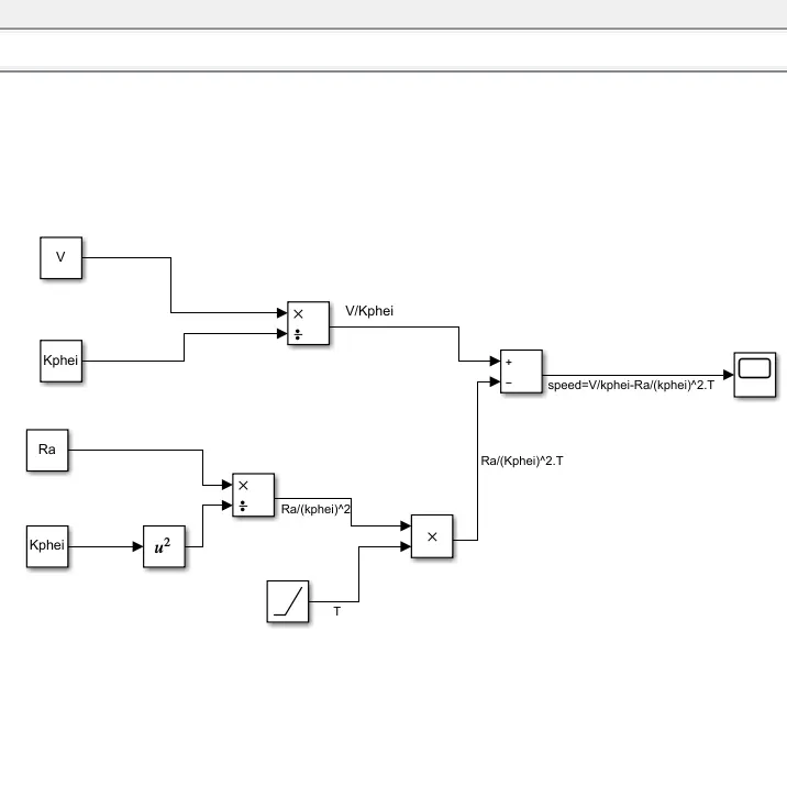
4.Assign the value in the matlab editor window.
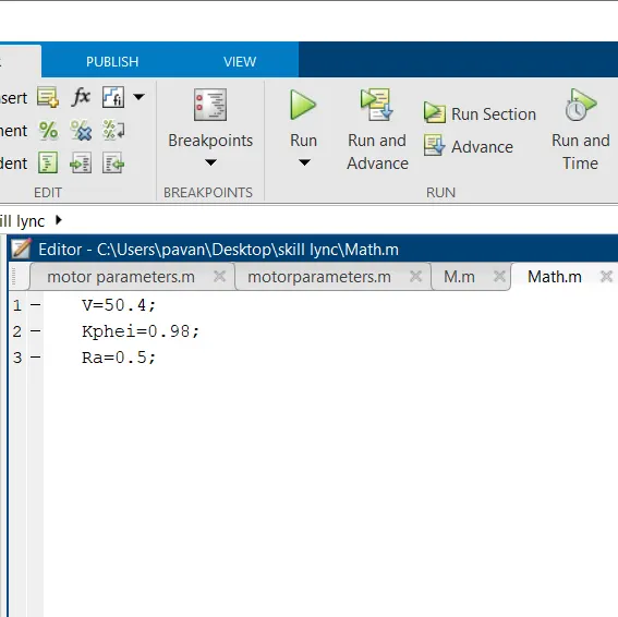
5.After assign all the value and the ramp signal is considered for the torque(T) input.
6.Click on the run icon .the sample time is 10 seconds. The output of the waveform is shown on the scope.
7.The result of the waveform is shown below.
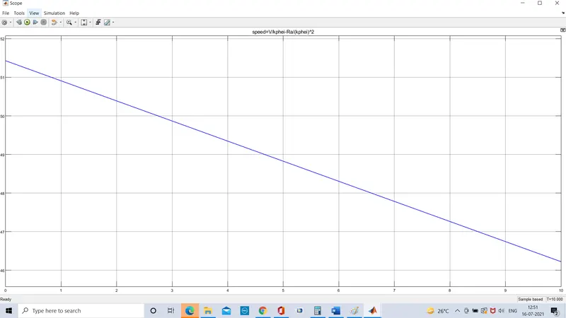
Hence the mathematical model of the torque -speed characteristic of DC motor is obtained.
4. Induction Versus DC brushless motors by Wally Rippel, Tesla
Explain in brief about author’s perspective.
A. In that odious world of gas powered vehicles, engines are not all alike. There are flat-heads, Hemis, straight, opposed, and V configurations.By doing the research on the engines for the production of the best one. But there is no such type of engines rather rather there are different types of engines to suit personal requirements, such as price and performance. This is also true for electric vehicle drives.
Toda Lead has been replaced by lithium and DC by either Brushless or Induction. Contactors, meanwhile, have given way to modulating inverters.
How the motors will work a brief description is given below.
With brushless machines, the rotor includes two or more permanent magnets that generate a DC magnetic field (as seen from the vantage point of the rotor). In turn, this magnetic field enters the stator core (a core made up of thin, stacked laminations) and interacts with currents flowing within the windings to produce a torque interaction between the rotor and stator. As the rotor rotates, it is necessary that the magnitude and polarity of the stator currents be continuously varied – and in just the right way - such that the torque remains constant and the conversion of electrical to mechanical energy is optimally efficient. The device that provides this current control is called an inverter. Without it, brushless motors are useless motors.
Let’s move on to induction motor drives. A forerunner of the 3-phase induction motor was invented by nikola tesla sometime before 1889. Curiously, the stators for the 3-phase induction motor and the DC brushless motor are virtually identical. Both have three sets of “distributed windings” that are inserted within the stator core.
The basic difference between these two machines is rotor.Unlike the DC brushless rotor, the induction rotor has no magnets – just stacked steel laminations with buried peripheral conductors that form a “shorted structure.” Currents flowing in the stator windings produce a rotating magnetic field that enters the rotor. In turn, the frequency of this magnetic field as “seen” by the rotor is equal to the difference between the applied electrical frequency and the rotational “frequency” of the rotor itself. Accordingly, an induced voltage exists across the shorted structure that is proportionate to this speed difference between the rotor and electrical frequency. In response to this voltage, currents are produced within the rotor conductors that are approximately proportionate to the voltage, hence the speed difference. Finally, these currents interact with the original magnetic field to produce forces – a component of which is the desired rotor torque.
When a 3-phase induction motor is connected to utility type 3-phase power, torque is produced at the outset; the motor has the ability to start under load. No inverter is needed. (Were an inverter needed, Tesla’s invention would have been useless until sometime in the 1960s.) The fact that induction motors are directly compatible with conventional utility power is the main reason for their success. In contrast, a brushless DC motor produces no starting torque when directly connected to fixed frequency utility power. They really need the aid of an inverter whose “phase” is ma intained in step with the angular position of the rotor.
While using the 3-phase induction motors on the utility power has great advantage and there is severe limitations on the starting torque,peak load torque and the load torque of the motors when compared to dc motors. The induction motor is doesnot operate on DC. The shaft speed is proprotinately to the line frequency so it is called a constant speed machines.
From the above limitations of the machine if we add an inverter control to the machine it is possible to vary the variable speed conditions.Add some feedback loops such that the inverter produces the exact frequency that the motor “desires,” and the induction motor is now capable of competing with DC and DC brushless for vehicle applications.
The difference between the DC brushless machine and the induction motor
Today, all the hybrids are powered by DC brushless drives, with no exceptions. The only notable uses of induction drives have been the General Motors EV-1; the AC propulsion vehicles, including the tzero; and the Tesla Roadster.
For both the machine the stator construction is same.the only difference is in rotors and inverte controls and the digital controllers and thecontrollers of control code.DC brushless drives require an absolute position sensor, while induction drives require only a speed sensor; these differences are relatively small. The dc brushless machines are operate at unity powerfactor and the cooling arrangement is easier whereas incase of induction motor they operate at 85 percent of the power factor that means the peak point energy efficiency for a DC brushless drive will typically be a few percentage points higher than for an induction drive. Induction machines are more difficult to control. The control laws are more complex and difficult to understand. Achieving stability over the entire torque-speed range and over temperature is more difficult with induction than with DC brushless.
The two machines are using the permanent magnets for creation of flux between the stator and rotor. The magnetic field strength produce by the permanent magents.When maximum torque is required, especially at low speeds, the magnetic field strength (B) should be maximum – so that inverter and motor currents are maintained at their lowest possible values. This minimizes the I² R (current² resistance) losses and thereby optimizes efficiency. Likewise, when torque levels are low, the B field should be reduced such that eddy and hysteresis losses due to B are also reduced. Ideally, B should be adjusted such that the sum of the eddy, hysteresis, and I² losses is minimized. Unfortunately, there is no easy way of changing B with permanent magnets.
For the induction motor we will the V/f Control strategy for the magnetic field strength.This means that at light loads the inverter can reduce voltage such that magnetic losses are reduced and efficiency is maximized. Thus, the induction machine when operated with a smart inverter has an advantage over a DC brushless machine – magnetic and conduction losses can be traded such that efficiency is optimized.Induction drives may be the favored approach where high-performance is desired; peak efficiency will be a little less than with DC brushless, but average efficiency may actually be better.
By using the permanent magnets it is so expensive so the induction motors will likely retain a cost advantage over PM machines. Also, due to the field weakening capabilities of induction machines, inverter ratings and costs appear to be lower, especially for high performance drives. Since spinning induction machines produce little or no voltage when de-excited, they are easier to protect.
From the above discussions of the machines, controls and the advanatage we may conclude that DC brushless drives will likely continue to dominate in the hybrid and coming plug-in hybrid markets, and that induction drives will likely maintain dominance for the high-performance pure electrics.
The induction motors are used in the Tesla motor of the electric vehicle and the hybrid vehicles are used DC brushless motors as per the reference.These are difference i had noticed while studying as per my knowledge.
So from the author perspective there is no specifice type of the machine which is best suited for the production. Depending on the requirement of the personals the machine pereference will be changes.