Week-6 Challenge: EV Drivetrain
Aim: -
- To identify the types of power converter circuits employed in electric and hybrid electric vehicle.
- To calculate the steady state speed of an EV with given inputs if duty cycle is 70%.
- Refer to the blog and explain in brief about author’s
Study #1: -
Q1. Which types of power converter circuits are employed in electric and hybrid electric vehicle?
Power Electronic Converters: -
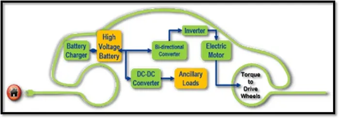
In Electric and Hybrid Electric Vehicles (EV/HEV), the power electronic converters are considered as the key elements that interface their power sources to the drivetrain of the EVs. In order to design highly efficient converters for the EV’s power system, advanced DC/DC and DC/AC converters are required to adapt the output voltage and current levels with high power quality.
The 3 types of converters which are widely used in an Electric Vehicle are:
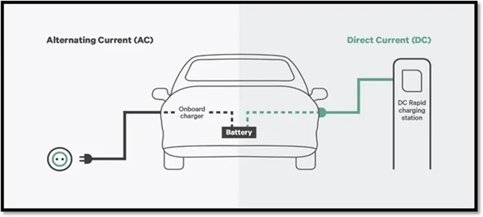
AC – DC Converter (On Board Charger): -
AC to DC converters are most commonly used in Plug-in Hybrid Electric Vehicles (PHEV) & Plug-in Electric Vehicles (PEV). These vehicles get their propulsion power from an external electricity source (charging stations) which is alternating current. The battery needs to be charged using a direct current source. For this purpose, AC to DC converter is employed in a PHEV & PEV.
Isolated converters:
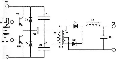
Half bridge: A half-bridge converter is a type of DC-DC converter that, like flyback and forward converters, can supply an output voltage either higher or lower than the input voltage and provide electrical isolation via a transformer.
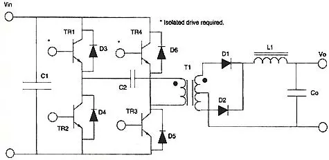
Full bridge: The full-bridge converter adds two additional transistors to the half-bridge converter. This means that four transistors are available to provide power to the output section, so this type of converter is used in power supplies in excess of 1000 Watts. Fig. 1 shows the schematic of the full-bridge converter. Each transistor has a clamping diode connected across its collector-emitter terminals and they are driven alternately in pairs. Transistors T1 and T3 are energized together for one half-cycle, and transistors T2 and T4 are energized together for the other half-cycle. One advantage of the full-bridge converter is that it only requires one capacitor for smoothing the output voltage, whereas the half-bridge converter required two. The full-bridge converter will be used in larger power supplies usually over 1000 Watts. Since this type of converter is more complex, it's normally used in the largest types of power supplies.
Push pull: As the switch-mode power supply has evolved, additional adjustments to the original circuits have been made to get more power from smaller components. This means that the efficiency for the system must be increased. One simple way to do this is to use a center-tapped transformer that utilizes both the top and bottom half-cycles.
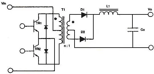
shows a schematic of the push-pull converter in which the push-pull converter utilizes a center-tapped transformer for both the primary and secondary windings. The primary winding is controlled by two transistors, which allow one of them to conduct during each half-cycle, so the output is receiving voltage directly through one of them at all times. This means that the efficiency of this configuration is approximately 90%. This allows the overall size for the power supply to be smaller for a comparable power supply whose efficiency is 75% to 80%.
DC – DC Converter: -
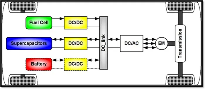
DC-DC converters can be used to interface the elements in the electric power train by boosting or chopping the voltage levels. By introducing DC/DC converters one can choose the voltage variation of the devices and the power of each device can be controlled. The power of the DC/DC converter depends on the characteristics of the vehicle such as top speed, acceleration time from 0 to 100 Km/h, weight, maximum torque, and power profile (peak power, continuous power).
Type of DC-DC Converter :-
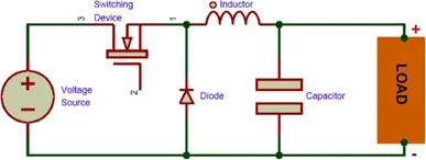
Buck- A buck converter (step-down converter) is a DC to DC power converter which steps down voltage from its input (supply) to its output (load). It is a class of switched mode power supply (SMPS) typically containing at least two semiconductors a diode and a transistor, although modern buck converters frequently replace the diode with a second transistor used for synchronous rectification and at least one energy storage element, a capacitor, inductor, or the two in combination. To reduce voltage ripple, filters made of capacitors (sometimes in combination with inductors) are normally added to such a converter's output (load-side filter) and input (supply-side filter).
Boost- A boost converter (step-up converter) is a DC to DC converter that steps up voltage from its input (supply) to its output (load). It is a class of switched mode power supply (SMPS) containing at least two semiconductors a diode and a transistor and at least one energy storage element: a capacitor, inductor or the two in combination. To reduce voltage ripple, filters made of capacitors (sometimes in combination with inductors) are normally added to such a converter's output (load-side filter) and input (supply-side filter).
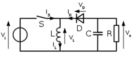
Buck-boost- The buck–boost converter is a type of DC to DC converter that has an output voltage magnitude that is either greater than or less than the input voltage magnitude. It is equivalent to a flyback converter using a single inductor instead of a transformer.
Cuk- The cuk converter is a type of buck-boost converter with zero ripple current. cuk converter can be seen as a combination of boost converter and buck-converter, having one switching device and a mutual capacitor, to couple the energy.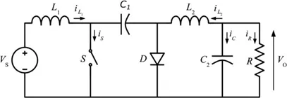
charge-pump- A charge pump is a kind of DC to DC converter that uses capacitors for energetic charge storage to raise or lower voltage. Charge-pump circuits are capable of high efficiencies, sometimes as high as 90–95%, while being electrically simple circuits.
DC – AC Converter (Inverter): -
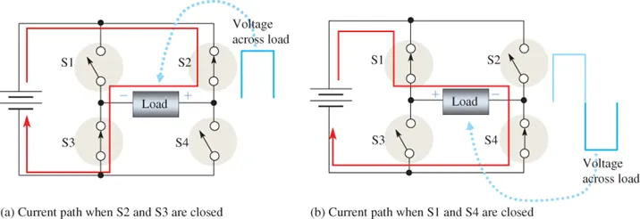
The DC/AC converter is required to convert the dc power to a suitable ac power for the electrical machine. The power output from battery pack (DC current) is converted using inverter to be used in electric motor (AC current).
Types of Inverter:-
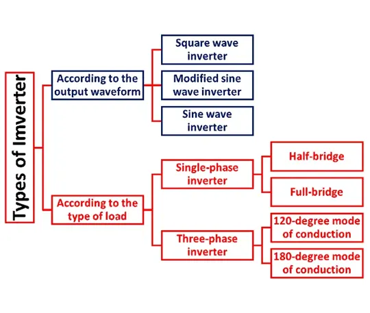
Square wave inverter:-
The square wave inverter is a type of inverter which converts solar DC power to AC power. The square wave inverter is simpler in design and more efficient than a sine wave inverter. However, the square wave will not be appropriate for some loads, because the large harmonic content can cause interference. Some electromechanical devices do not work well with square wave power. If the load is reactive, there will be loss of efficiency due to reactive power loss, so the efficiency advantage of the inverter may be nullified. Resistive loads also may suffer from radiated interference due to harmonic content.
Modified sine wave inverter:-
Modified sine wave inverter is a classification of power inverters whose wave form and power quality are superior to basic square wave inverter. The modified sine wave inverter’s wave form stays at zero volt for some time before any change in polarity.
sine wave inverter:-
If you’re a fan of camping or extensive road travel, but also enjoy modern conveniences that run on electricity, a sine wave inverter may be your new best friend. Sine wave inverters are devices that transform power from a battery into the same type of power you get from a typical wall outlet in your home or office.
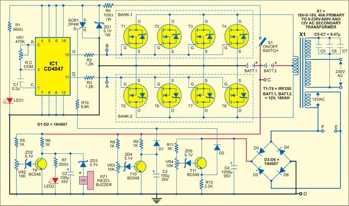
Specifically, sine wave inverters transform direct current (DC) from a battery into an alternating current (AC). The AC power can then be used to run appliances, lamps and light strips, compressors and other devices that cannot run directly on battery power.
The concept of a sine wave inverter is relatively straightforward, but things can get a bit more complicated when you start to browse through all the different sine wave inverters out there. You’ll find two main types of inverters: pure sine wave inverters and modified sine wave inverters. Once you know the differences between the two, you’ll know the right inverter to choose.
Study#2:
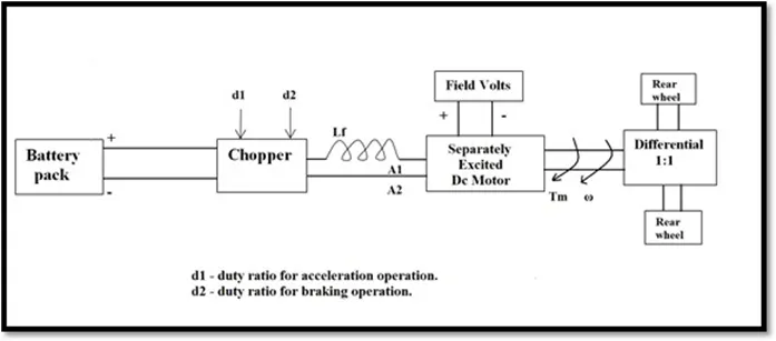
Q2. An Electric Vehicle's powertrain with 72V battery pack in shown in the diagram below. The duty ratio for acceleration operation is 'd1' and for the braking operation the duty ratio is 'd2'.
The other parameters of the electric vehicle is given below, Motor and Controller Parameters:
Rated Armature voltage= 72 V Rated armature current= 400 A Ra= 0.5Ω, KΦ= 0.7 Volt second
Chopper Switching frequency= 400 Hz
The vehicle speed-torque characteristics are given by the below equation

What is EV steady state speed if duty cycle is 70%?
Given: -
The following input parameters are given: - Battery pack voltage (V) = 72V
Rated armature current = 400 A Armature Resistance (Ra) = 0.5Ω Motor constant (KΦ) = 0.7
Chopper Switching frequency= 400 Hz Duty Cycle = 70%ω
Solution: -
Vehicle Output Voltage (Vv) is given by: - Vv = Battery Voltage (V) * Duty Cycle
Vv = 72 * 0.70
Thus, Vehicle voltage = 50.4V
Now, Equation for Vehicle torque is given by:
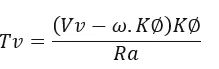
Where;
Tv= Vehicle Torque (N-m)
Vv = Vehicle voltage (Volts)
ω= steady state speed of vehicle (rps)
K∅ = Motor constant
Ra= Armature Resistance
Substituting all these values in equation, we get:
`T = ((50.04 − 0.7 ⋅ ω) ⋅ 0.7) / 0.5`
Tv = 70.56 − 0.98 ⋅ ω Tv = 24.7 + 0.0051 ⋅ ω2
Solving these two equations,
70.56 − 0.98 ⋅ ω = 24.7 + 0.0051 ⋅ ω2
We get a quadratic equation:
0.0051 ⋅ ω2 + 0.98 ⋅ ω − 46.94 = 0
Since quadratic equation, we get two values of ;
ω= 38.85 rad/s and ω = -230.95 rad/s
We take the positive value;
Steady state speed of vehicle = = 38.85 rad/s
Study#3:-
Q3. Develop a mathe.Tmatical model of a DC Motor for the below equation using Simulink.
ωω= V/Kϕ -Ra/Kϕ^2
INPUT Script
clear all
close all
clc

% Torque Speed Characteristics of DC Machine.
% Array of motor speed in rad/sec
Speed = linspace(0,500,50);

% Input of Speed constant of a motor  (rpm/v)
N_s   = input('Enter the value of Speed Constant of Motor = ');

% Input the Battery voltage supply value.(volts)
V   =  input('Enter the value of Voltage Supply = ');

%Input the Armature Resistance. (ohms)
R_a  =  input('Enter the value of Armature Resistance = ');

% Back E.M.F developed
EMF  =  1 ;  % back emf is directly proportional to speed constant given in the dat is per unit voltage

%Calculating the constant of proportionality in emf and speed relation
k_phi  =  (EMF*60)/(N_s*2*3.14);

% the DC motor Speed torque charateristics
% T = ((V*k_phi/R_a) - ((k_phi)^2/R_a)*omega)
% Calculation of Torque
 T  =  ((V*k_phi/R_a) - (((k_phi)^2/R_a).*Speed));


 % To calculate Total Current in Ampere
 TC  =  (V - EMF)/R_a;

 % To Calculate the maximum Torque
 T_max  = k_phi*TC ;


  %Convert Speed value in rpm from rad/sec
 Speed  =  Speed*60/(2*3.14);

 % Plotting the D.C.Machine charateristics w.r.t Speed Vs Torque
 plot(Speed,T,'color','r','linewidth',3);
 xlabel('Speed (RPM)');
 ylabel('Torque (Nm)');
 title('D.C.Machine Charateristics wrt Speed Vs Torque');
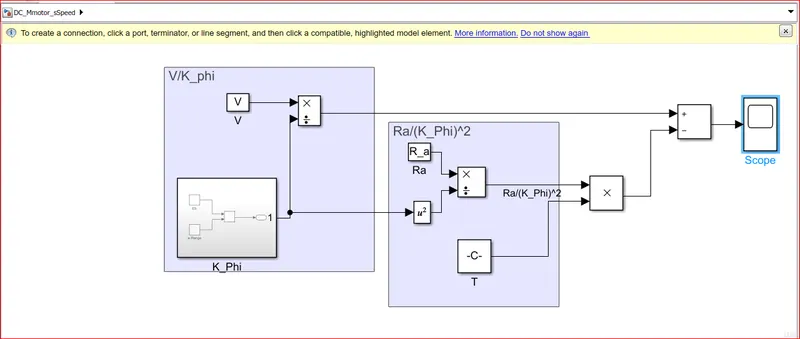
SIMULINK:-
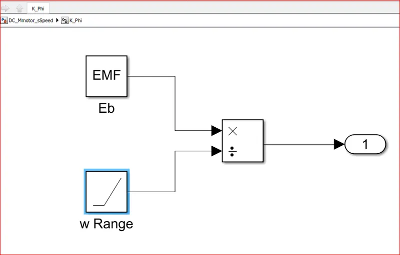
SUBSYSTEM:-
RESULTS:-
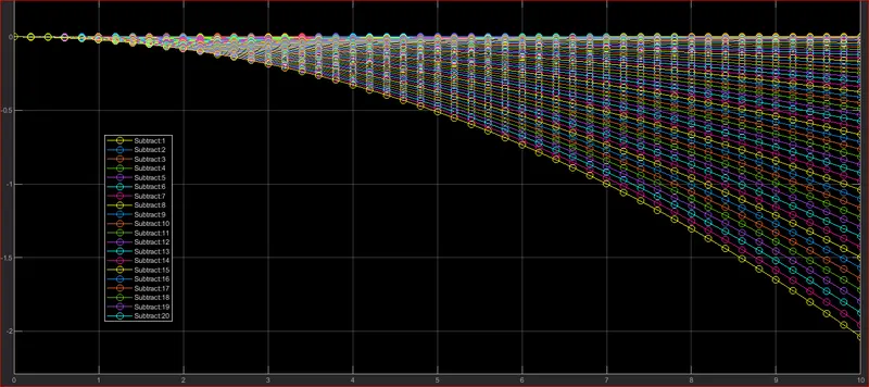
EXPLANATION:-
- The speed is determined with a help of mathematical model in simulink, By preparing the model which governs the above Speed formula.
- New model in Simulink is opened and saved with name DC_Mmotor_sSpeed,then in that model we take constant block it’s input is “V“ from the workspace.
- “K” is Eb/speed so we take “Eb” in constant block and it’s input as ”EMF” from the workspace.
- Further we take divide block and connect multiplication port to EB as it is directly proportional and divide port to Speed from workspace, and create a Subset of it with asking for output port block.
- In Similar way Subset is created for Ra/K^2*T as shown in Model diagram.
Study#4:
Q4. Refer to the blog on below topic:
Refers: https://www.tesla.com/blog/induction-versus-dcrushless-motors
Explain in brief about author’s perspective.
The following points can be concluded from the above topic:
In the beginning, author describes the dominance of Internal Combustion Engines (ICE) in the world of automobile industry and also discuss different types of engines. He explains that all engines were similar and it was up to the user to select according to their requirement. He also speaks about induction motor and brushless DC motors and presents his view that these two technologies will be widely used for the coming years.
Then he explains the working of both 3-phase induction motor and a brushless DC motor.
Now the author has done comparison between these two technologies and stated some advantages and disadvantages of each.
Induction motor have some advantages like: it has no magnets. The motor has the ability to start under load. No inverter is needed. Some disadvantages of Induction motors are: They cannot operate from DC; AC is a must. Shaft speed is proportionate to line frequency. Hence, when used with utility power, they are constant speed machines. When operated from utility power, they have limited starting torque and somewhat limited running peak torque capabilities, when compared to DC type machines.
Brushless DC motor have some advantages like: much less rotor heat is generated with the DC brushless drive. The peak point energy efficiency for a DC brushless drive will typically be a few percentage points higher than for an induction drive.
Some disadvantages of Brushless DC motor are: as machine size grows, the magnetic losses increase proportionately and part load efficiency drops.
Permanent magnets are expensive and difficult to handle due to very large forces that come into play when anything ferromagnetic gets close to them.
Finally the author couldn’t choose which drive is better than the other but makes it clear that DC brushless drives will likely continue to dominate in the hybrid and coming plug-in hybrid markets, and that induction drives will likely maintain dominance for the high-performance pure electrics.