Week -2
SIMULATION OF DOOR BELL USING SOLENOID AND THERMISTOR CONTROLLED FAN :-
AIM :-
To make a Simulink model for doorbell using solenoid and thermistor to sense a heater to control the fan for cooling.
OBJECTIVES :-
- Generate a Simulink model of doorbell using solenoid.
- Generate a Simulink model of a thermistor to sense the temperature of a heater to control the fan for cooling.
SIMULINK MODEL OF DOORBELL USING
What is solenoid ?
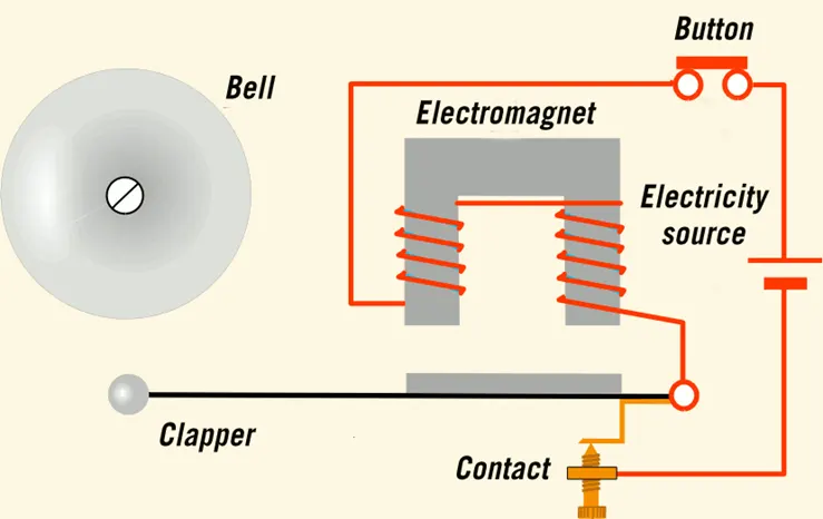
A solenoid is a device comprised of a coil of wire, the housing and a moveable plunger (armature). When an electrical current is introduced, a magnetic field forms around the coil which draws the plunger in. More simply, a solenoid converts electrical energy into mechanical work
SOLENOID THEORY :-
The door bell works under the principle of magnetic field where the soft iron armature gets attracted to the magnetic field generated by the copper wounding (Electromagnet) when electricity is passed through them.
SIMULINK MODEL :-
BLOCKS USED :-
- Pulse Generator – To generate time signals to control the switch operation
- Scope – For viewing the graph of the signals
- Simulink-PS – To convert Simulink environment to Real Time environment
- SPST Switch – An ON/OFF control switch (Single Pole Single Throw Switch)
- Battery – Power source for the bell to ring
- Electrical & Mechanical References – Denoting that all the electrical and mechanical blocks are grounded
- Solenoid block – To generate magnetic field to attract the hammer to ring the bell
- PS-Simulink – To convert Real Time environment to Simulink environment
FLOW PROCESS :-
- In the pulse generator signals are generated for every 2 sec to control the switch to ring the bell.
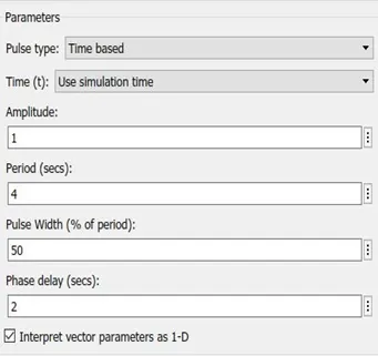
- The generated signals are plotted and then converted to real time environment.
- Then according to the signal, the switch acts to control the flow of the current to the
- When the current is passed to the solenoid it generates magnetic field to attract the iron armature.
From the solenoid the Motion is sensed using Ideal Motion Sensor then the signals are converted to Simulink phase to record the motion of the hammer.
RESULTS :-
GENERATED TIME PLOT,
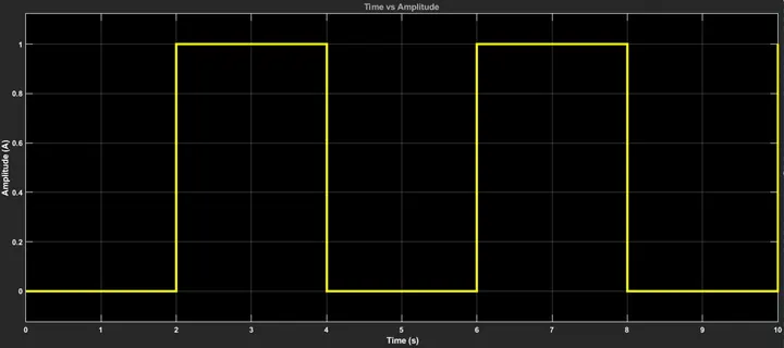
It’s understood that the time pulse is generated for every 2 seconds to control the switch in a time span of 50 sec.
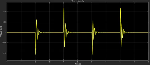
VELOCITY PLOT (HAMMER),
POSITION PLOT (HAMMER),
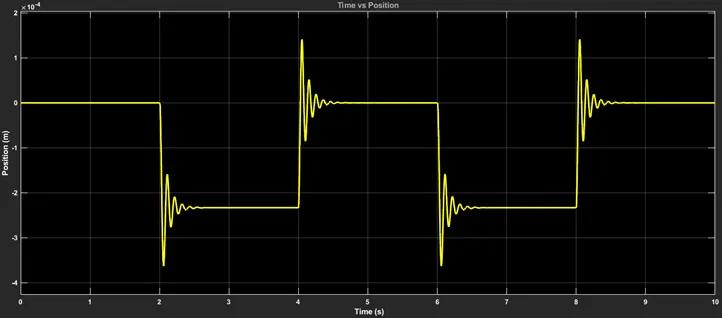
From the velocity and position plots it’s understood that the bell is rung for every 2 sec in a time span of 50 sec.
SIMULINK MODEL OF A THERMISTOR TO SENSE THE TEMPERATURE OF A HEATER TO CONTROL THE FAN FOR COOLING
THEORY :-
The setup completely depends on thermistor where the resistance changes w.r.t temperature. And the sensed resistance is used to generate voltage respectively to control a circuit.
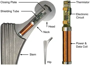
The thermistor is basically a two-terminal solid state thermally sensitive transducer constructed using sensitive semiconductor-based metal oxides with metallised or sintered connecting leads formed into a ceramic disc or bead. This allows the thermistor to change its resistive value in proportion to small changes in ambient temperature. They can operate up to by producing good resistance versus temperature.
SIMULINK MODEL :-
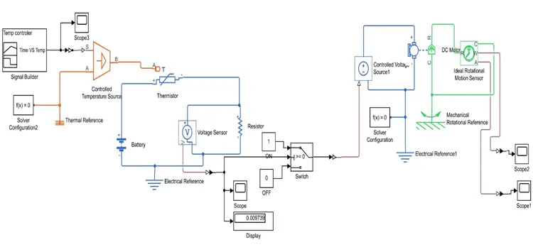
BLOCKS USED :-
- Signal Builder – For inputting temperature at different time intervals
- Scope – For viewing the graph of the signals
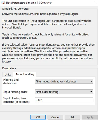
- Simulink-PS(at signal builder block) – To convert Simulink environment to Real Time environment
At this Simulink-PS block the input is continuous so the input handling parameters will be changed
- Thermistor – To sense the temperature for producing resistanc
- Battery – Power source
- Simulink-PS – To convert Simulink environment to Real Time environment
- Voltage Sensor – To sense the voltage across the circuit
- Display – To view the threshold value of the voltage
- PS-Simulink – To convert Real Time environment to Simulink environment
- (Threshold Controlled) Switch – To control the voltage output at particular threshold value
- Control Voltage Source – To separate the voltage into (+ & -)
- DC Motor – To run at controlled voltage
- Ideal Rotational Motion Sensor – To sense the working of DC Motor
- Electrical & Mechanical References – Denoting that all the electrical and mechanical blocks are grounded
FLOW PROCESS :-
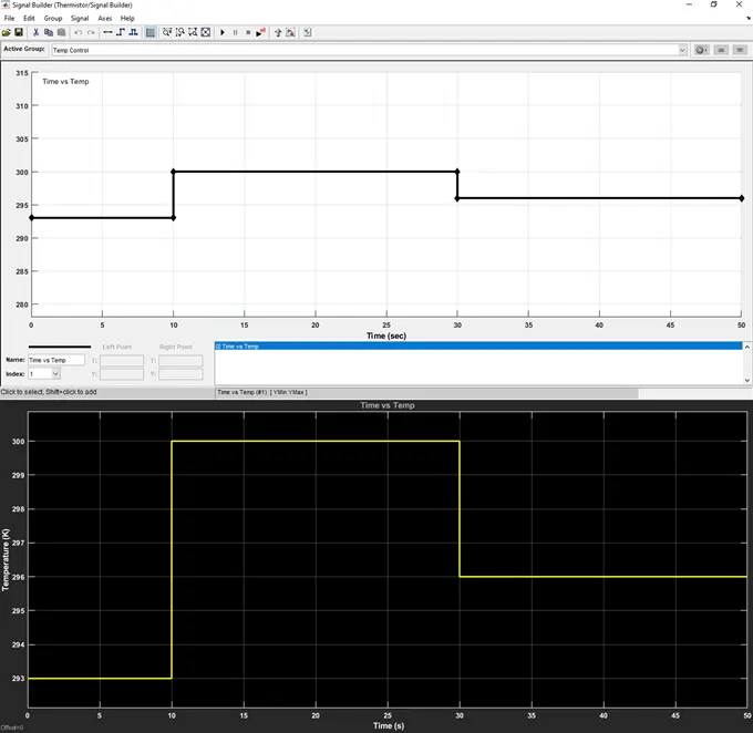
- The signal builder generates the time interval with various temperature as a source of
Conditions of Heat Source,
T = 20 Degree Celcius for (0-10 s) T = 27 Degree Celcius for (10-30 s) T = 23 Degree Celcius for (30-50 s) Condition for FAN,
T = 25 Degree Celcius > ON T = 25 Degree Celcius < OFF
- Next the temperature data is passed to the thermistor to sense and generate the resistance value As the resistance (R) varies accordingly to the Current (I), voltage across it being sensed using Voltmeter (Voltage Sensor).
- That voltage is inputted to (threshold controlled) switch for turning ON the Motor (Fan) with a threshold value of ‘0.0090509’.
- Then the particular value (T=27 respective Voltage) the DC Motor is turned
- Using the Ideal Rotational Motion Sensor the activities of DC Motor is obtained for plotting the Velocity and Angular Displacement
RESULTS :-
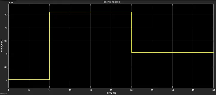
TIME vs VOLTAGE,
From this plot we can conclude that the voltage is generated according to the temperature input w.r.t time. So the maximum voltage at T=27 Degree Celcius is 0.0107 V.
TIME vs CONTROLLED VOLTAGE,
From this plots we can understand that the voltage is obtained for (10-30 s) at T=27 Degree Celcius to turn ON the motor. The threshold value used is ‘0.0090509’.
TIME vs VELOCITY,
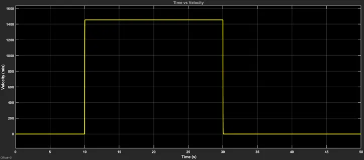
TIME vs ANGULAR DISPLACEMENT,
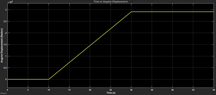
From the above two plots we can conclude that the fan (DC MOTOR) was turned ON when the temperature exceeds T = 25 Degree Celcius. Here out of three inputs, T = 27 Degree Celcius is where it exceeds T = 25 Degree Celcius so the fan will be turned ON (Time = 10-30 s).