Week-6 Challenge: EV Drivetrain
ELECTRIC VEHICLE DRIVETRAIN
AIM 1:
Which types of power converter circuits are employed in electric and hybrid electric vehicle?
EXPLAINATION :
Now-a-days Power electronics have a very wide usage in the automobile part which are necessary to accomodate many features in the vehicle within a compact room.
Inside the electric and hybrid electric vehicles the power converters role is much more important so that they are in the consideration of automobile industry.
POWER CONVERTERS :
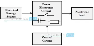
The task of a power converter is to process and control the flow of electric energy by supplying voltages and currents in a form that is optimally suited for the user loads. Energy was initially converted in electromechanical converters (mostly rotating machines).
A power converter is made of high-power fast-acting semiconductor devices, such as bipolar junction transistor (BJT), metal oxide semiconductor field effect transistor (MOSFET), insulated gate bipolar transistor (IGBT), silicon-controlled rectifier or thyristor (SCR), gate turn-off SCR (GTO), and MOS-controlled thyristor (MCT). These solid-state devices configured in a certain circuit topology function as an on-off electronic switch to convert the fixed supply voltage into variable voltage and variable frequency supply. All of these devices have a control input gate or base through which the devices are turned on and off according to the command generated by the controller. Tremendous advances in power semiconductor technology over the past two decades enabled the development of compact, efficient, and reliable DC-DC and DC-AC power electronic converter topologies.
The main types of power converters in HEV and EV are :
- AC to DC type (Rectifiers)
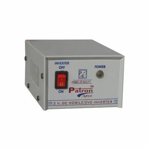
- DC to AC type (Inverters)
- DC to DC type (Choppers)
- AC to AC type (Throttling)
There are also some of the topologies on the power is converter i.e, high to low or low to high.
- Buck-converter
- Booster-converter
- Buck-Booster-converter
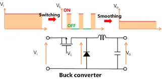
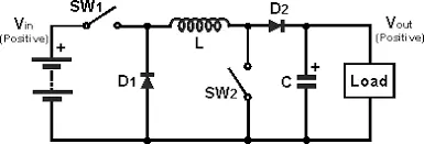
Buck Converter:The buck converter is step down converter and produces a lower average output voltage than the dc input voltage. The below is the image showing the Buck power converter.
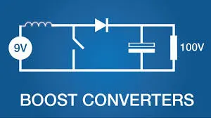
Boost converter: The output voltage is always greater than the input voltage in the boost converters and below is the image showing the boost converters.
Buck-Boost converter: The output voltage can be either higher or lower than the input voltage, below is the image showing the Buck-boost power converter.
AIM 2 :
An Electric Vehicle's powertrain with 72V battery pack in shown in the diagram below. The duty ratio for acceleration operation is 'd1' and for the braking operation the duty ratio is 'd2'.
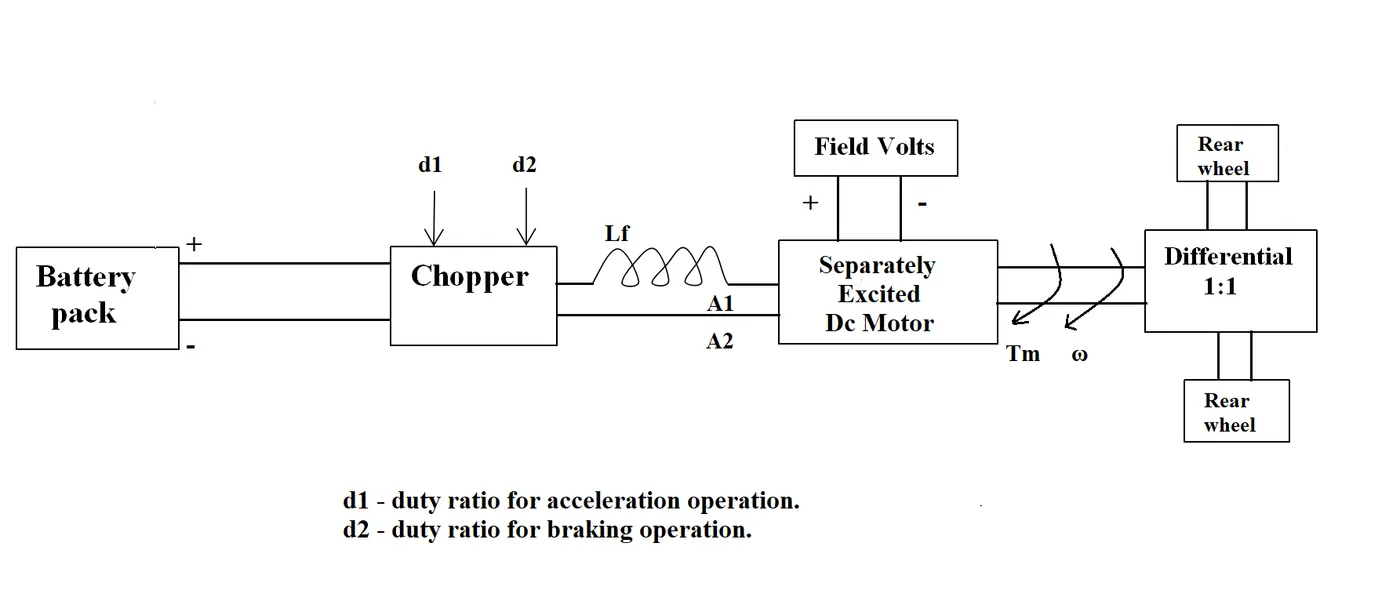
The other parameters of the electric vehicle is given below,
Motor and Controller Parameters:
- Rated Armature voltage= 72 V
- Rated armature current= 400 A
- Ra= 0.5Ω, KΦ= 0.7 Volt second
- Chopper Switching frequency= 400 Hz
The vehicle speed-torque characteristics are given by the below equation:

What is EV steady state speed if duty cycle is 70%?
EXPLAINATION :
Given data :
Armature Voltage = 72 V
Armature current = 400 A
Ra = 0.5 ohms
Current constant KΦ = 0.7
Chopper switching = 400 Hz
Vehicle torque = 24.7+(0.0051)*w^2
Motor torque Equation (Tm) = (V×(KΦ/Ra)-(KΦ²/Ra)×ω
Applied voltage to motor with 70% duty cycle = 72*0.7
Applied voltage to motor with 70% duty cycle = 50.4 V
Motor torque Equation (Tm)
= 50.4×(0.7÷0.5)-(0.7²/0.5)×ω
Motor Torque(Tm) = 70.56-0.98ω
At steady state :
motor torque = Vehicle torque
24.7+0.0051ω² = 70.56-0.98ω
0.0051ω²+0.98ω-45.86=0
ω = 38.9149 rad/sec
Executing in Matlab for reference :
clear all
close all
clc

%inputs
Ra = 0.5;
K_fi = 0.7;
I = 400; %total current
omega = linspace(0,1000,100);
V = 72*0.7;
T_motor = 70.56-0.98*omega; %Maximum torque of the motor.
T_vehicle = 24.7+(0.0051)*omega.^2;
omega =(V/K_fi)-(Ra*(T_motor/K_fi)); %torque calculation of motor
%plot of torque Vs speed i.e, motor characteristics

plot(omega,T_vehicle,'color','r','linewidth',2);
hold on
plot(omega,T_motor,'color','g','linewidth',2)
xlabel('angular speed(rad/sec)');
ylabel('Torque(Nm)');
legend('T_vehicle Vs angular Speed','T_motor Vs angular speed');
grid on
axis ([20 100 0 100])
From the above code by comparing the both Vehicle and motor characteristic equations from the given data we can conclude that the value of angular velocity is approximatley equal to the theoritical value.
OUTPUT :
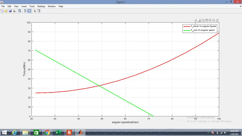
From the output graph we can say that the mating point of the two plots is known as steady state of the vehicle,motor torque and speed will be same.
AIM 3 :
Induction Versus DC brushless motors by Wally Rippel, Tesla
From the above article explain the author's perspective ?
EXPLAINATION :
From the above article the author(wally rippel) is trying to differentiate between the 3phase induction motor and the DC brushless motors and which one will stand in the front of the coming automobile era.
From his view point author has main focus to differentiate as DC brushless motor has inverter which gives a good acceleration performance compared to AC inverter less induction motor. If AC induction motor is arranged with an inverter it gives a good acceleration irrespective of torque.
But at finally author has not given the top priority in between these two motors and both has their advantage in the era of automobiles and both of them may operate side by side in the future.
| DC Brushless motor | AC Induction motor |
| With brushless machines, the rotor includes two or more permanent magnets that generate a DC magnetic field (as seen from the vantage point of the rotor). In turn, this magnetic field enters the stator core (a core made up of thin, stacked laminations) and interacts with currents flowing within the windings to produce a torque interaction between the rotor and stator. As the rotor rotates, it is necessary that the magnitude and polarity of the stator currents be continuously varied – and in just the right way - such that the torque remains constant and the conversion of electrical to mechanical energy is optimally efficient. | A forerunner of the 3-phase induction motor was invented by Nikola Tesla sometime before 1889. Curiously, the stators for the 3-phase induction motor and the DC brushless motor are virtually identical. Both have three sets of “distributed windings” that are inserted within the stator core. The essential difference between the two machines is with the rotor. |
| Without an inverter this Brushless DC motor is waste of construction as it gives good vary in the speed as current is easily varied. | Here a 3-phase induction motor is connected to utility type 3-phase power, torque is produced at the outset; the motor has the ability to start under load. No inverter is needed.The fact that induction motors are directly compatible with conventional utility power is the main reason for their success |
| In contrast, a brushless DC motor produces no starting torque when directly connected to fixed frequency utility power. They really need the aid of an inverter whose “phase” is maintained in step with the angular position of the rotor. | They cannot operate from DC; AC is a must. Shaft speed is proportionate to line frequency. Hence, when used with utility power, they are constant speed machines. Finally, when operated from utility power, they have limited starting torque and somewhat limited running peak torque capabilities, when compared to DC type machines. |
CONCLUSION :
- Explained types of power converter circuits are employed in electric and hybrid electric vehicle.
- Obtained the value of angular speed at the steady state.
- Described the author's perspective about DC brushless motor and 3-phase induction motor.
GOOGLE DRIVE LINKS :