Week-6 Challenge: EV Drivetrain
1. Types of power converter circuits are employed in electric and hybrid electric vehicle
Power converter:
The power semiconductor devices or power electronic converter fall
generally into six categories :
- AC to DC Converter (Controlled Rectifier)
- DC to DC Converter (DC Chopper)
- AC to AC Converter (AC voltage regulator)
- DC to AC Converter (Inverter)
-Rectifiers(AC to DC Converter):
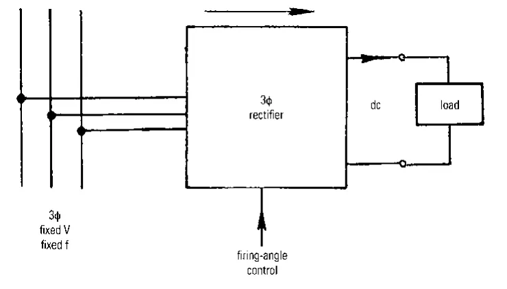
The process of electrical rectification is where current from an ac supply is converted to an unidirectional form before being supplied to a load .The ac supply current remains bidirectional, while the load current is unidirectional. With resistive loads the load voltage polarity is fixed. With energy storage loads and alternating supply voltage the load current is unidirectional but pulsating, and the load voltage in series-connected load inductance elements may vary and alternate in polarity during the load current cycle.A diode rectifier circuit converts AC voltage into a fixed DC voltage. The input voltage to rectifier could be either single phase or three phase.
 -
-
Inverter(DC to AC Converter):
The process of transferring power from a dc supply to an ac load is known as inversion, and the necessary form of converter is usually known as an inverter. Inverters can be classed according to their manner of commutation, that is, by the process by which conducting switches are extinguished.An AC to DC converter circuit can convert AC voltage into a DC voltage. The DC output voltage can be controlled by varying the firing angle of the thyristors. The AC input voltage could be a single phase or three phase.
-DC Chopper(DC to DC Converter):
DC to DC converter is very much needed nowadays as many industrial applications are dependent upon DC voltage source. The performance of these applications will be improved if we use a variable DC supply. It will help to improve controllability of the equipments also. Examples of such applications are subway cars, trolley buses, battery operated vehicles etc. We can control and vary a constant DC voltage with the help of a chopper.
Chopper is a basically static power electronics device which converts fixed DC voltage/power to variable DC voltage or power. It is nothing but a high speed switch which connects and disconnects the load from source at a high rate to get variable or chopped voltage at the output.
-AC voltage regulator(AC to AC Converter):
AC to AC converters is used for converting the AC waveforms with one particular frequency and magnitude to AC waveform with another frequency at another magnitude. This conversion is mainly required in case of speed controlling of machines, for low frequency and variable voltage magnitude applications as well. We know that there are different types of loads that work with different types of power supply like single-phase, three-phase supply, and the supplies can be differentiated based on the voltage and frequency range also.
-conclusion:
In the electric and hybrid electric vehicles from the above only three power coverters are used ,they are AC to DC Converter (Controlled Rectifier),DC to DC Converter (DC Chopper),DC to AC Converter (Inverter). This is because the battery source used in the electric and hybrid electric vehicles are DC in nature so that there is no use for AC voltage regulator(AC to AC Converter).
2.Given:
Motor and Controller Parameters:
Rated Armature voltage(Vin)= 72 V,
Rated armature current(Iin)= 400 A,
Armature resistance(Ra)= 0.5Ω,
Motor constant KΦ= 0.7 Volt second
Chopper Switching frequency= 400 Hz
The vehicle speed-torque characteristics are given by the below equation

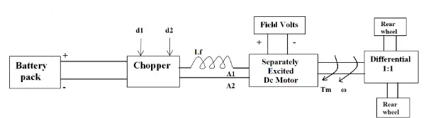
As from the before sessions we know the torque from which we need to find out the speed in rad/sec,the equation is as follows
T=((V*k) /Ra)-((k^2)*w)/Ra)
where T-Torque,
w-Total Speed
Comparing the two torque equation of the vehicle and motor we can identify the total speed,
24.7+0.0051*w^2= ((V*k) /Ra)-((k^2)*w)/Ra)
24.7+0.0051*w^2=((72*0.7*)/0.5)-((0.7*0.7/0.5)*w/0.5)
24.7+0.0051*w^2=70.56-0.98*w
w^2+192.15*w-8992.15=the above equation can be simplified by the quadratic equations method,
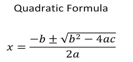

After simplfying the equation from the above formula we get and the speed can not be a negative quantity the negative value is neglected,
w=38.95 rad/sec.
3. Induction Versus DC brushless motors by Wally Rippel, Tesla
The author writes this blog to entail the differences between the two most commonly used motor drives in the automobile industry: the DC brushless motor drive and the induction motor drive. Rippel goes in to detail about the differences in construction, working, and cost between the two drive types. However, with what he has written, he has not arrived at the conclusion that one type is better than the other. In the last lines of the opening paragraph, Rippel writes that "there is no one best engine type" and that it is all a matter of personal preference when it comes to choosing an engine. It is in this same regard that he ends the blog stating that there is still 'no winner' when it comes to motor drive selection either. In spite of both motor drive types having similarities, they also have their benefits and drawbacks.