Week 6 Challenge
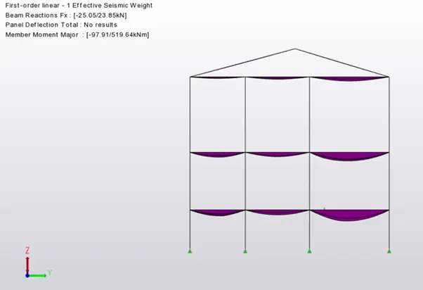
1.Summarize your study for the bending moment, shear force and deflection diagrams for the elements of the model.
Ans)
Bending Moment: It refers to the internal rotational moments that cause a section to bend. In the case of a beam, it can be calculated as the algebraic sum of the moments about the section of all forces acting on either side of the section, where a sagging moment will make the beam concave (positive) upwards at that section, and vice versa for a hogging moment (i.e. negative).The below diagram basically is an example of the shear force and bending moment of a simply supported beam subjected to a point load on the centre.
Shear Force:It refers to the force acting along on a surface. Basically, the force forms no inclination to the surface on which it is acting on. Within a beam, the shear force at any section is basically the algebraic sum of the lateral forces acting on either side of the section. For example, take a look at this beam:
Consider a beam carrying loads W1, W2 and W3 with R1 and R2 as the support reactions. If we cut the beam at section AA, then since the resultant forces at the left of section AA is F upwards, then the shearing force at section AA is F downwards.
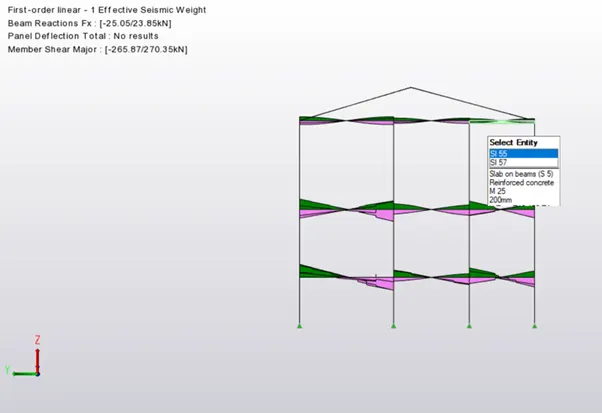
It is important to calculate both the shear force and bending moment because it is extremely handy when it comes to structural design. By determining the values of the shear force and bending moment across a structural member, we can accordingly decide the appropriate material or size that can help it to withstand these internal forces and moments. This is crucial because using the wrong material or size can ultimately cost the structural elements its integrity for failing to support the designed loads.
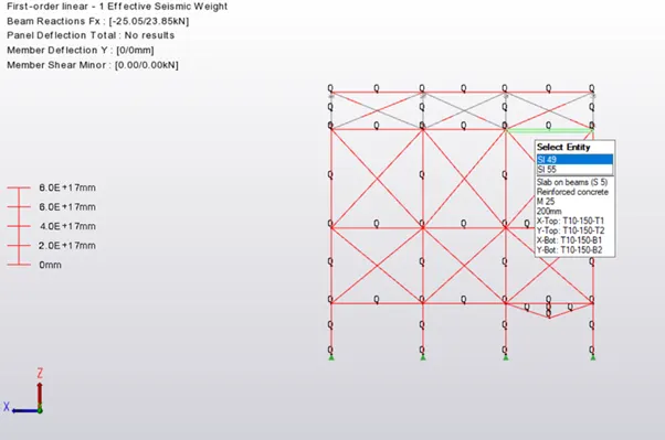
Deflection Diagram: It is the degree to which a structural element is displaced under a load. It may refer to an angle or a distance.The deflection distance of a member under a load can be calculated by integrating the function that mathematically describes the slope of the deflected shape of the member under that load.
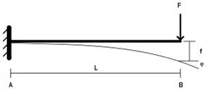
Deflection (f) in engineering.
2.Based on the analysis design the members and outline the thought process in selecting the member sizes along with the foundation design.
Ans)
Aim : To analyse the design members and outline the thought process in selecting the member sizes along with the foundation design.
Tools Required:
-> Loads
-> Loadcases
-> Seismic load
-> Validate
-> Check Member -> Static
-> Foundation
-> Properties
Procedure:
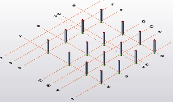
- Firstly open the model that was previously designed.
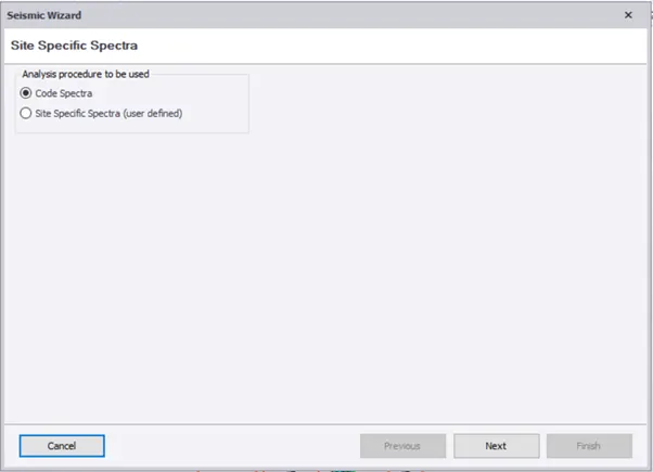
- Now under the load cases we need to select the seismic load and that will direct you to a new dialogue box.
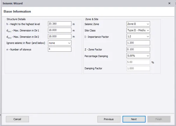
- Now in that dialogue box you will asked to select and check all the values, check weather the values of the 1.00.
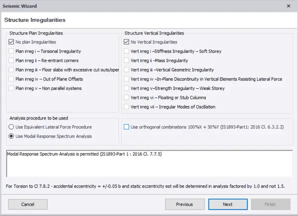
- Now you will be directed to new dialogue once you click next option.
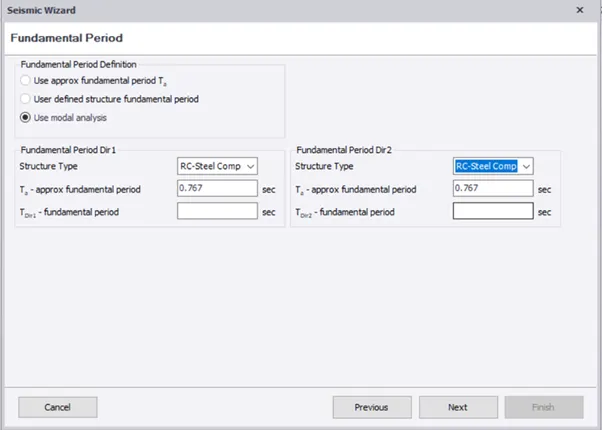
- The dialogue boxes that appear in this process helps us to design the seismic load to the following structure.
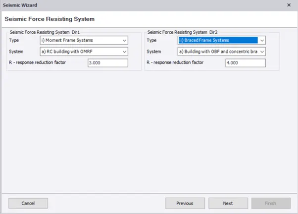
- Once all the parameter such as length, width, height and many more check is done click on Finish.
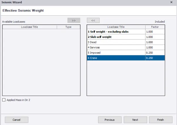
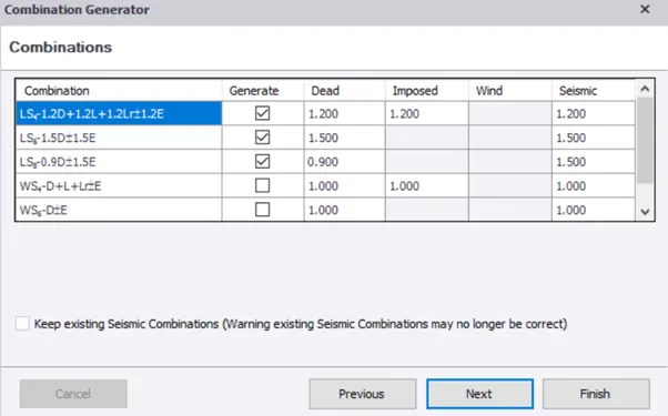
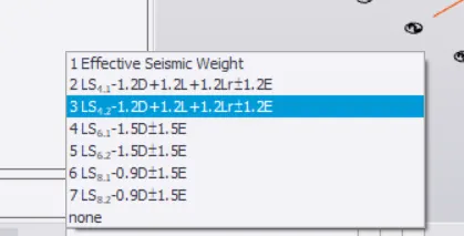
- Now if we open the down load bar we can find the seismic loads that have been applied to the structure.
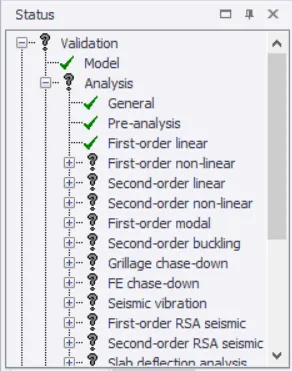
- Now that all the loads are applied we can now validate the structure to see and errors.
- If any errors found they would be listed under the validate option and when we click on the error we will be directed to that error place and it is highlighted with a solid arrow.
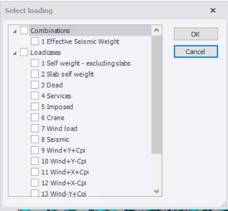
- Correct the error by changing the size of the particular beam or column.
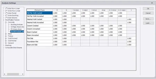
- Now select the analyse option on the top task bar, under that we have to click the 1st order liner option.
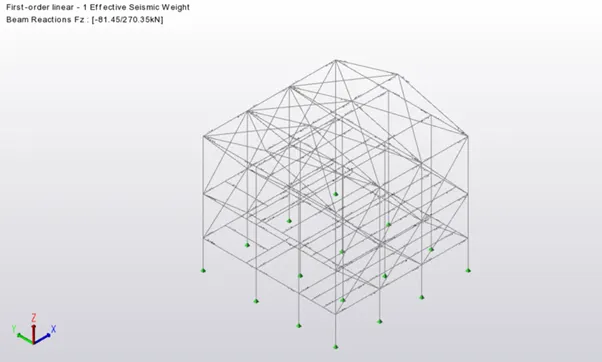
- Now the analysis is done and will show us the errors once it is done.
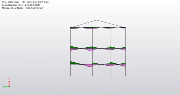
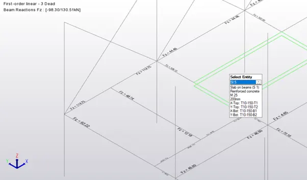
- Now click on the particular member and when we do the left click on it we get a dialogue box under that select the check member option and under that select the static option which displays another dialogue box.
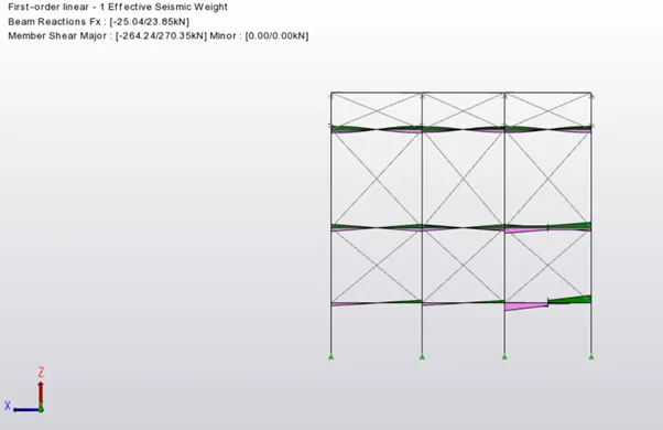
- Now in the new dialogue box we can find the load analysis manually done and there we can check the value that is obtained of the loads that we have give or the material that we have chosen.
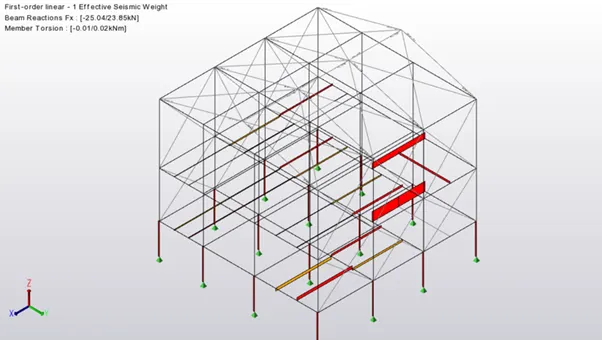
- Now check the values that we obtained by manual calculations and check the actual value that has to come out with the help of IS Code book.
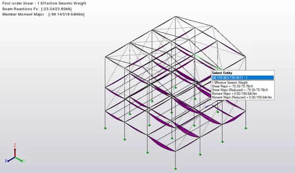
- Now change the size of the structural members accordingly.
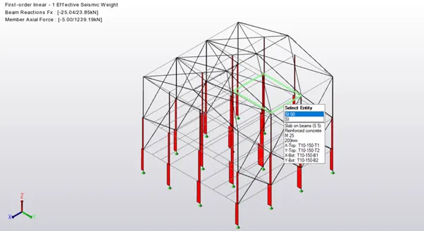
- Also attach proper foundation that is required to support the structure.
Result:
Hence by following the above series of steps we will able to analyse a design members of the structure.