Week 6- Challenge
Challenge-6
Meshing the Car Hood
Aim:
To mesh the given car hood model as per the mentioned quality criteria.
Abstract:
The given geometry is a car hood i.e., a sheet metal and has 5 components which are to be mid surfaced due to minimum thickness and is to be meshed as per the given quality criteria.
Methodology:
- Create a mid surface for every component and create a property for each.
- Clean up the component so that there will be no errors created while meshing the component.
- Start meshing the component uniformly from one side to another for better mesh flow.
- Remove any errors if occurred in the mesh.
Introduction:
A car hood is a hinged cover that rests over the engine of a front-engine vehicle. Its purpose is to provide access to the engine for repair and maintenance. A concealed latch is typically used to hold down the hood. The following challenge is to mesh the given car hood model as shown in the below figures.
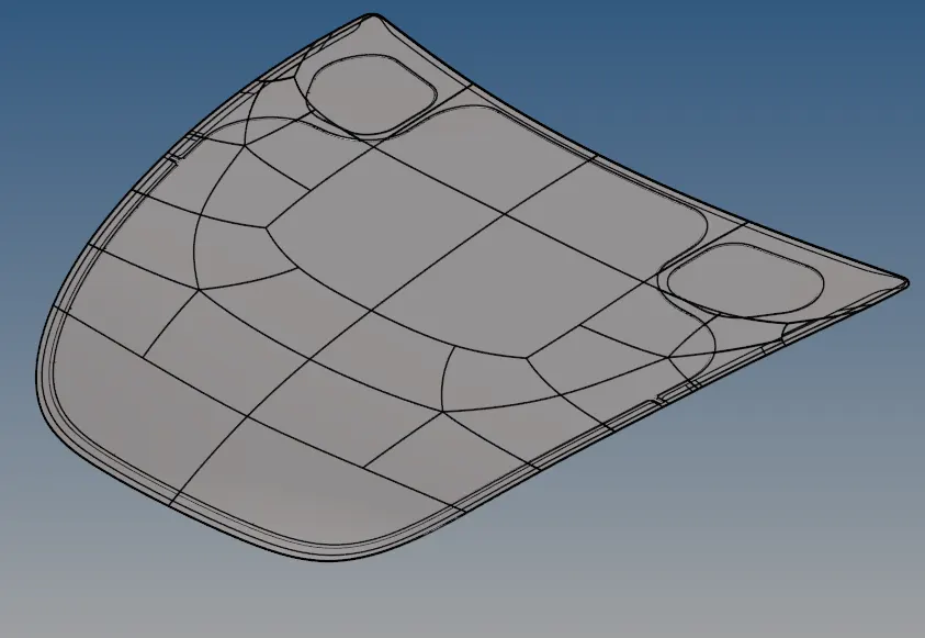
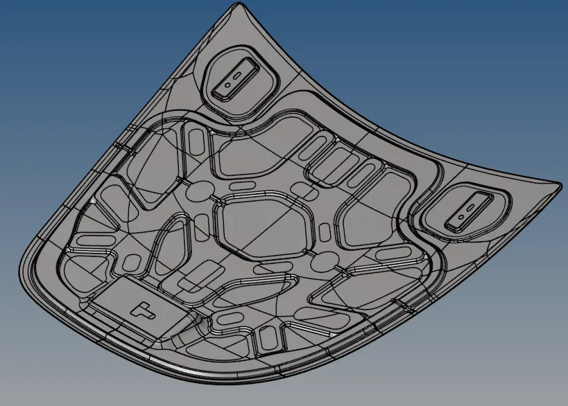
Fig 1: Car hood outer side Fig 2: Car hood inner side.
Procedure:
- The given geometry has 5 components, Which are to be mid surfaced and meshed.
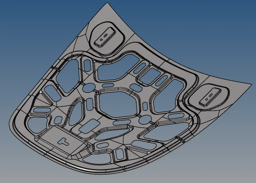
Fig 3: Outer hood Fig 4: Inner hood
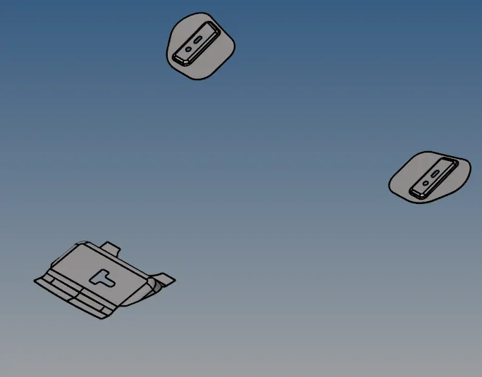
Fig 5: Hinge components.
2. Considering the first hinge component in fig 5, create a mid surface for the component and clean up the given mid surface by removing unnecessary lines and nodes which will damage the mesh flow of the component.
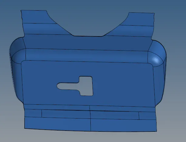
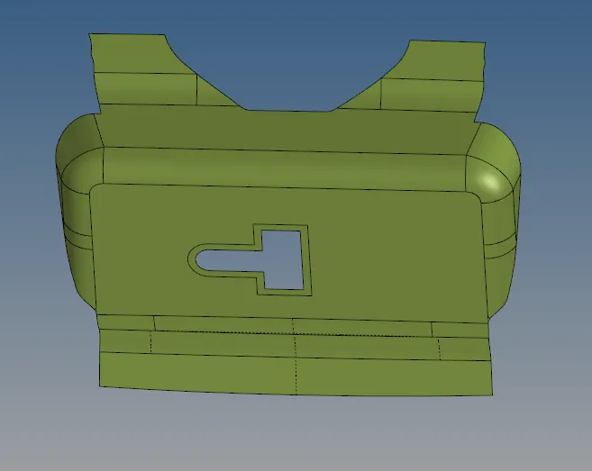
Fig 6: Original geometry. Fig 7: mid surfaced geometry
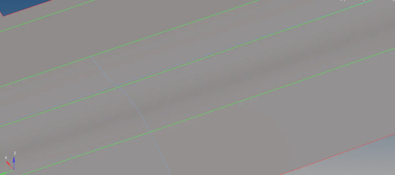
Fig 8: Geometry cleaned component
In fig 8 the green lines are to be represented as feature lines which helps in maintaining the shape to the component. Whereas the blue dotted lines are hidden and maintain the structure and can be converted back to normal lines if needed.
3. Start meshing the component mentioning the target length as 5mm and mentioning the quality criteria in the quality index menu so that the errors may be visible and can be rectified.

Fig 9: Quality criteria
4. The mesh of the component must be in quad elements. The tria elements are to be removed by dragging them using the drag tria elements in the quality index menu. Few tria elements can be maintained in the curved areas so that there may be no formation for rotating quad elements. The mesh flow should be as shown in the figure below.
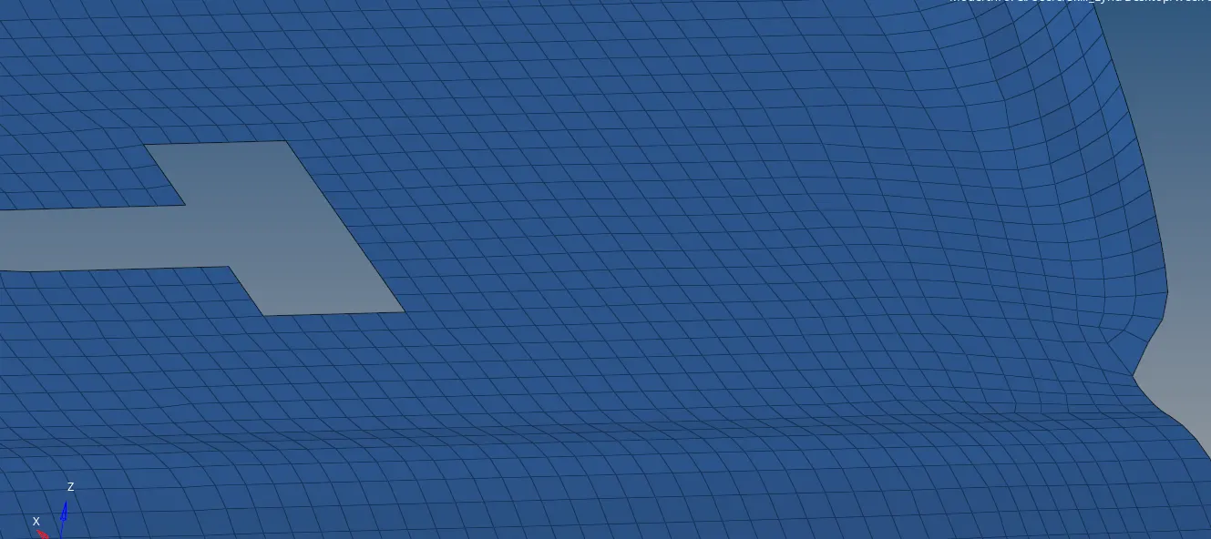
Fig 10: Quad mesh flow.
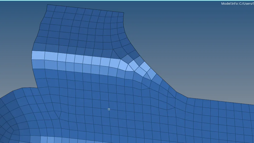
Fig 11: tria element flow.
The tria elements should not be maintained on a free edge for the surface.
5. After correcting the mesh flow the elements should be optimised and smoothed so that the mesh is spread uniformly through the component.
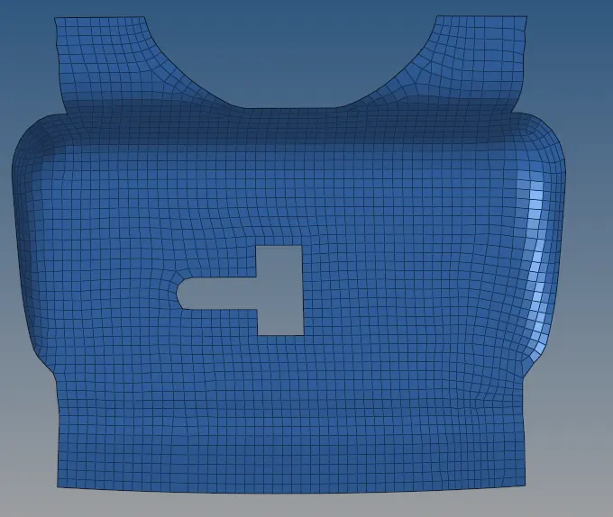
Fig 12: meshed component 1
6. Continue the process for the remaining components maintaining the good mesh flow as showing below.
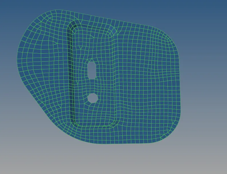
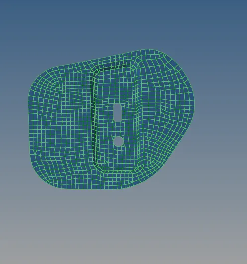
Fig 13: Hinge component 1 Fig 14: Hinge component 2
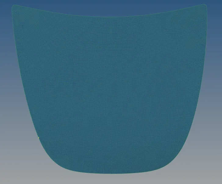
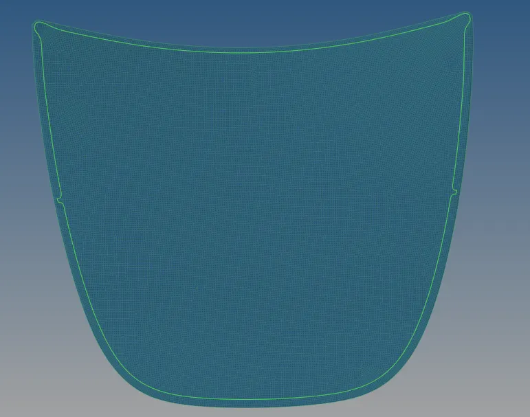
Fig 15: Outer hood top view. Fig 16: outer hood inner view.
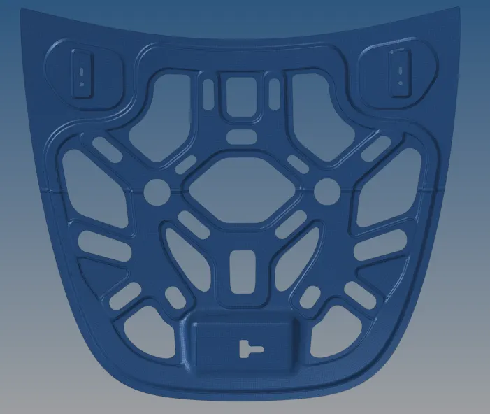
Fig 17: inner hood
7. In fig 16 the component is cut into half and meshed so that the remaining half part is reflected, Thus saving time for meshing the component.
8. Use the mesh correction tools in the quality index for the correction of the mesh flow such as element optimize, node placing, drag tria, split quad elements etc.
Result:
Thus meshing the given components according to the quality criteria is completed.
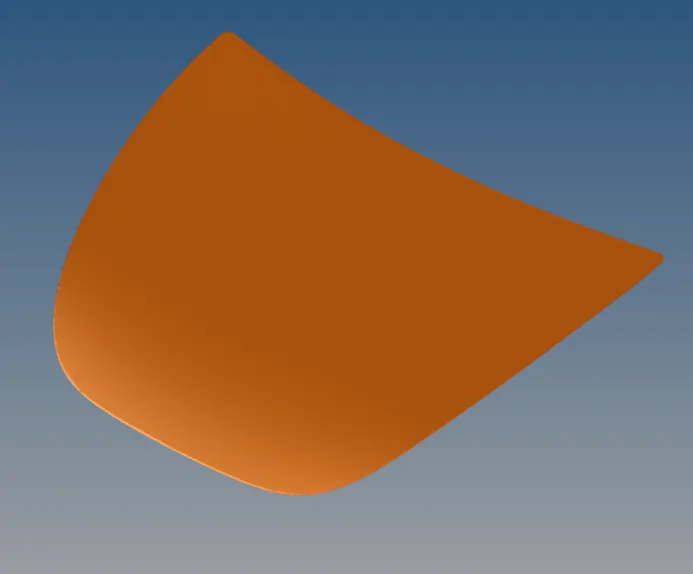
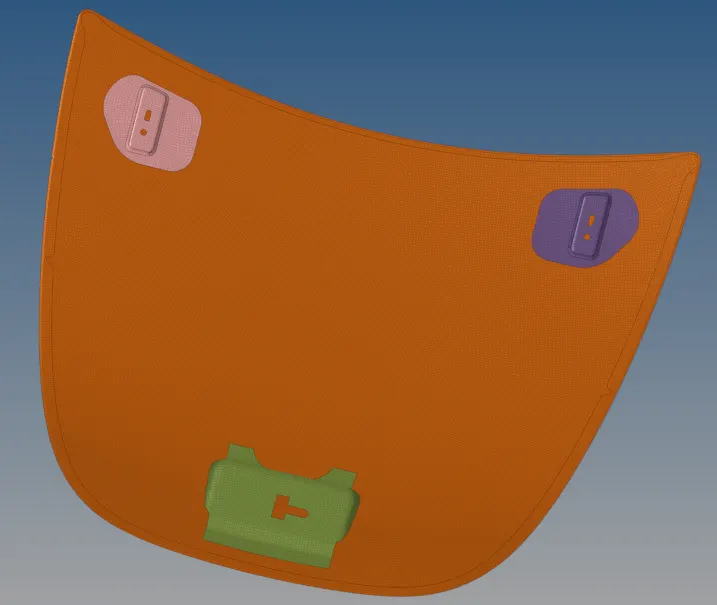
Fig 18: outer hood. Fig 19: hinge components inside the outer hood .
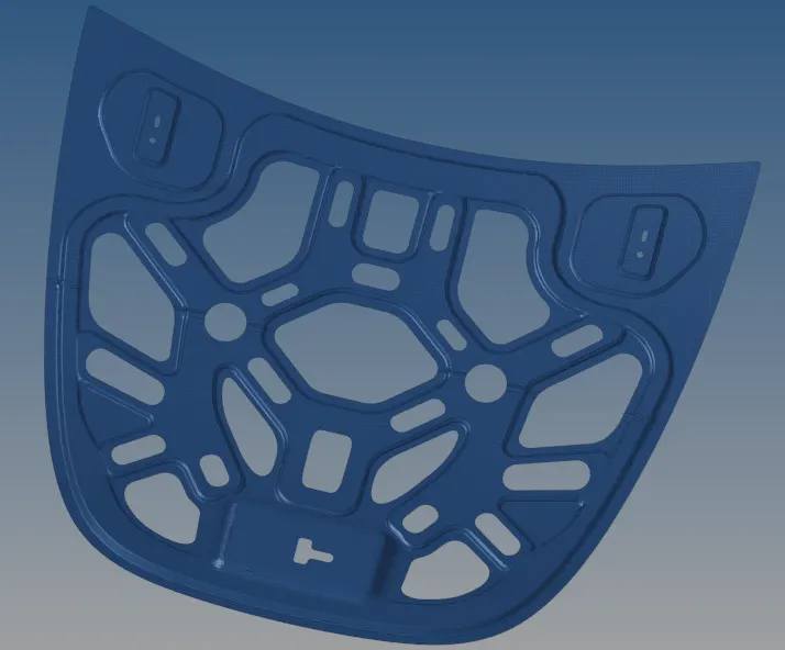
Fig 20: Inner hood component
Learning outcome:
- Learned to clean up the component.
- Learned to maintain a good mesh flow.
- Learned to reflect the components.
Challenge link:
https://drive.google.com/file/d/1jS3tZim-FZm9RDymk_9fuUwe5UanhfpJ/view?usp=sharing