Week 6 Challenge
- To Analyze and design the raft foundation by applying earth pressure, self-weight, surcharge loading and 70R vehicle loading and calculating bending moment, shear force & deflection through staad. pro as well as by manual calculation also.
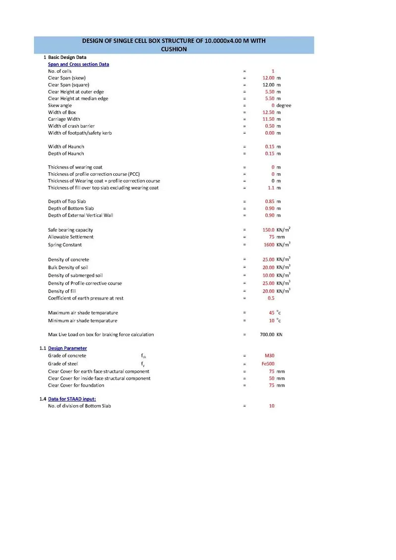
- So first of all the Vehicular underpass is modelled as a portal frame structure in Staad.pro and analyzed for a unit length.
- Various loads as described applied to the structure and were analyzed.
- Spring foundation assigned to the structure as per the calculated value for different springs as per the length of the nodes considered for the spring foundation.
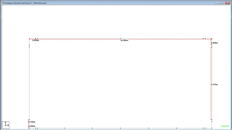
The Staad model has been created according to the sizes given.
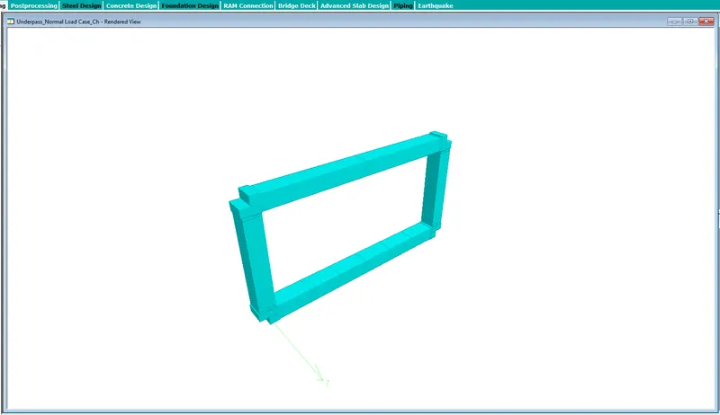
- The 3D render view of the model.
Manual Calculation
1. Self Weight of the bottom Slab
The thickness of the bottom slab = 0.9m
Width of the Underpass = 12.0m
Thickness of wall = 0.9m
Volume of slab = (12+2 x 0.9) x 0.9 x 1 = 12.42 m3
Slf wt of slab = 12.42 x 2.5 = 31.05 t
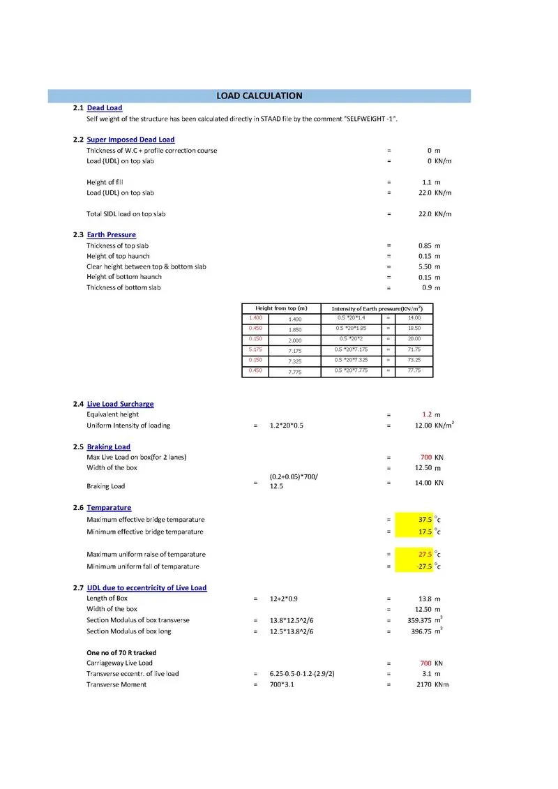
2. Earth Pressure Calculation
phi = 30 degree
earth pressure co-efficient = 0.5
Density of soil = 20 Kn/m3
| Height from top (m) | Intensity of Earth pressure(KN/m2) | |||
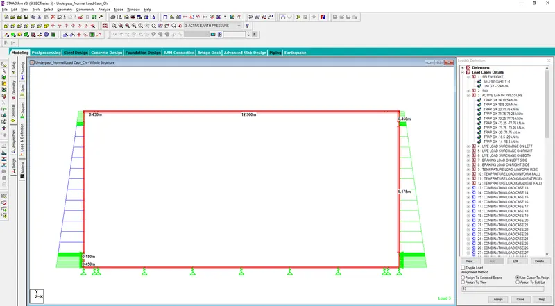
| 1.400 | 1.400 | 0.5 *20*1.4 | = | 14.00 |
| 0.450 | 1.850 | 0.5 *20*1.85 | = | 18.50 |
| 0.150 | 2.000 | 0.5 *20*2 | = | 20.00 |
| 5.175 | 7.175 | 0.5 *20*7.175 | = | 71.75 |
| 0.150 | 7.325 | 0.5 *20*7.325 | = | 73.25 |
| 0.450 | 7.775 | 0.5 *20*7.775 | = | 77.75 |
3. Live load surcharge
| Equivalent height | = | 1.2 | m | |||
| Uniform Intensity of loading | = | 1.2*20*0.5 | = | 12.00 | KN/m2 |
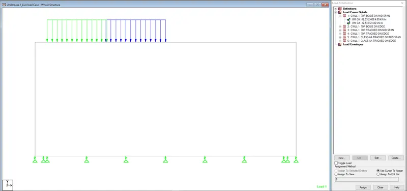
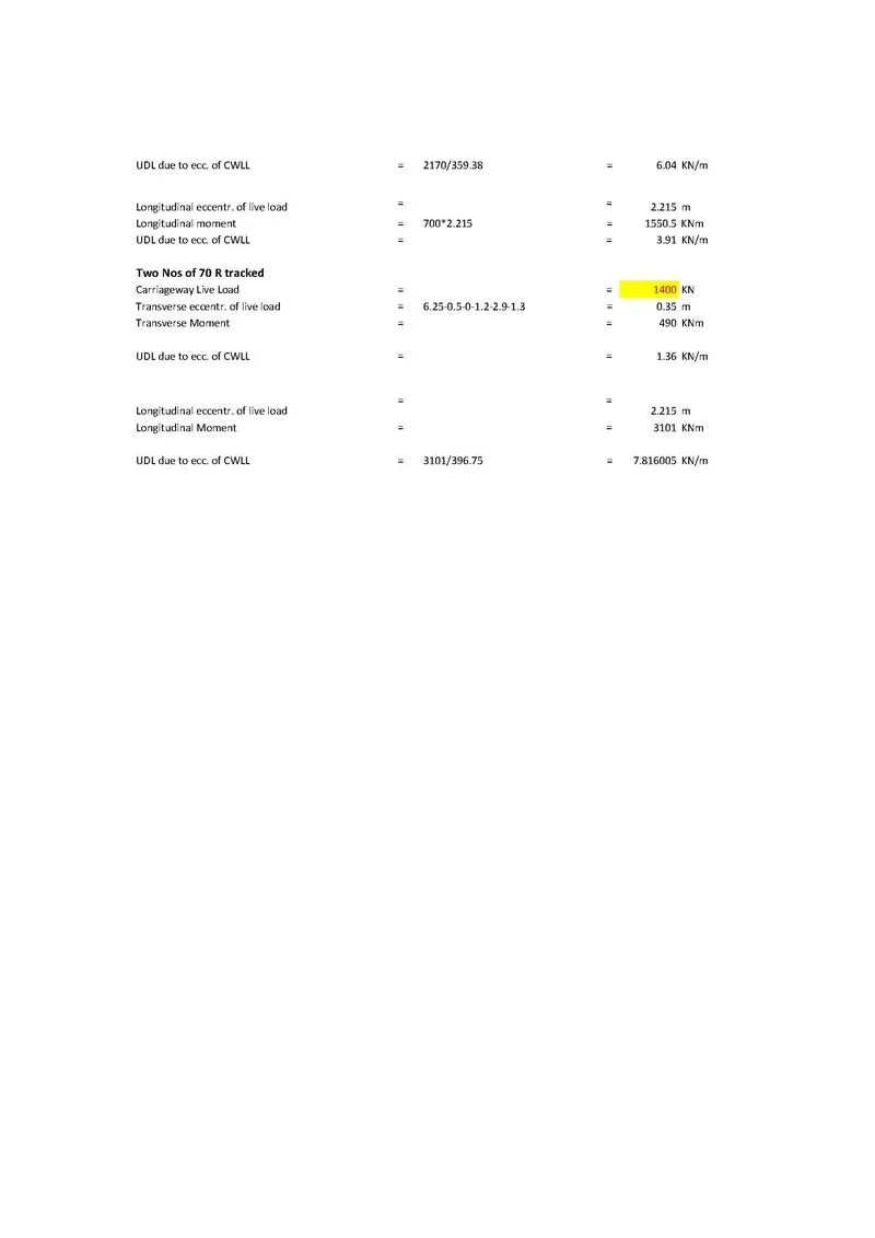
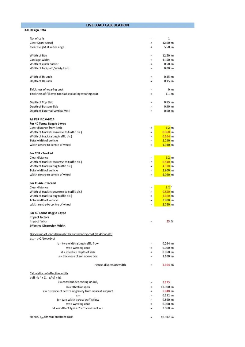
4. 70R load
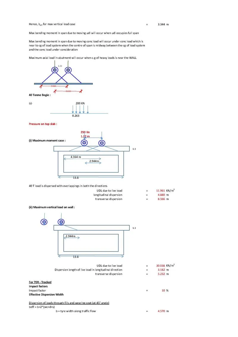
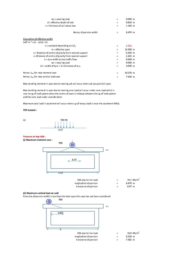
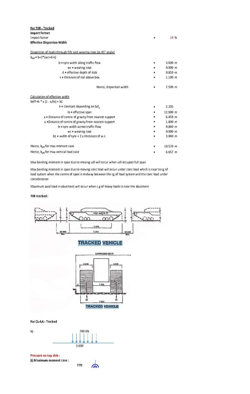
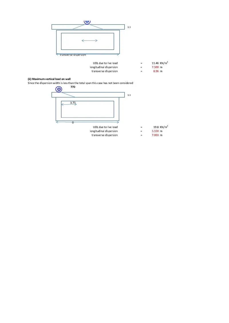
For 70R loading 70ton of vehicular loading is being applied on the structure.
Applying in staad model
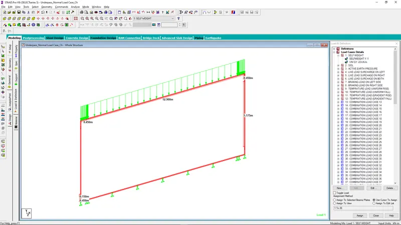
1. Self Weight
Self wt has been applied to the structure by inputting the self wt. as -1 in staad.
2. Earth Pressure
The Earth pressure is applied to the structure from top to bottom in trapezoidal format.
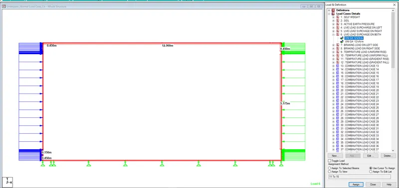
3. Live load surcharge
4. 70R load
Bending Moment, SFD & Deflection
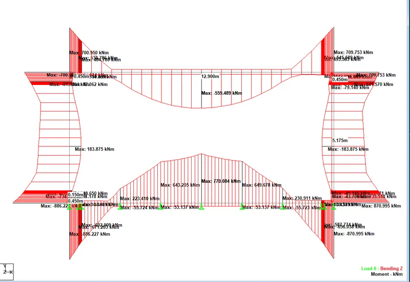
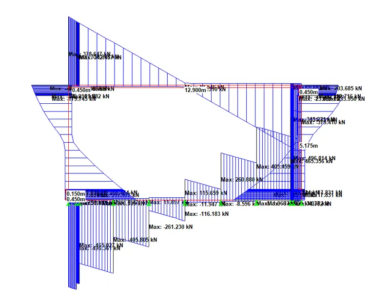
1. Self Weight
BM-
SF-
Deflection-
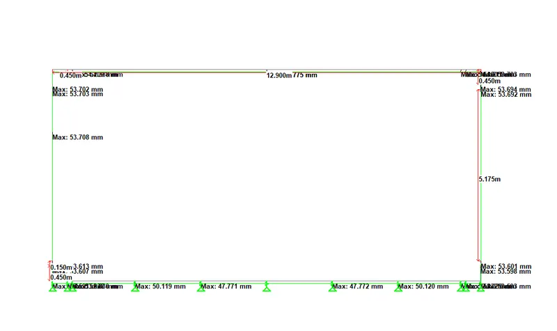
2. Earth Pressure
BM-
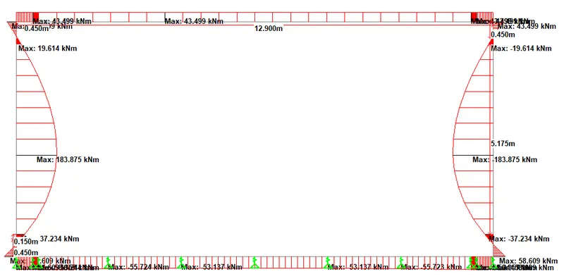
SF-
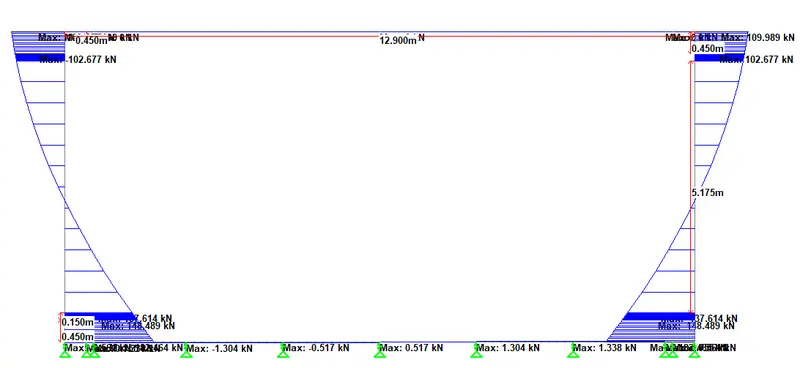
Deflection-
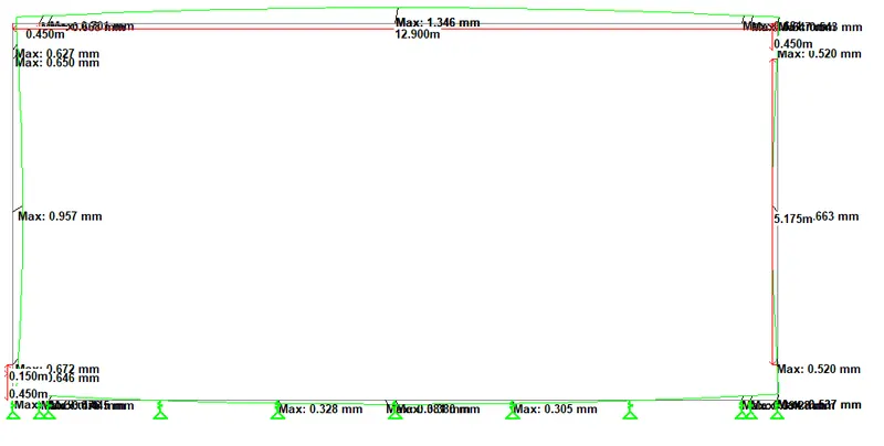
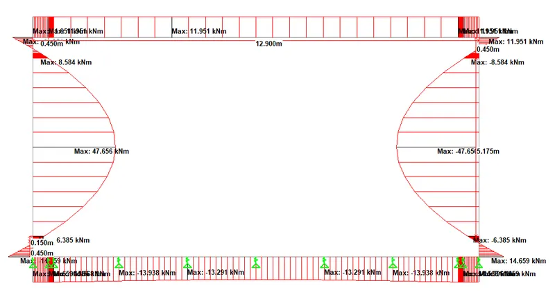
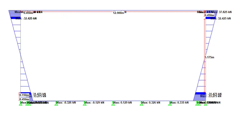
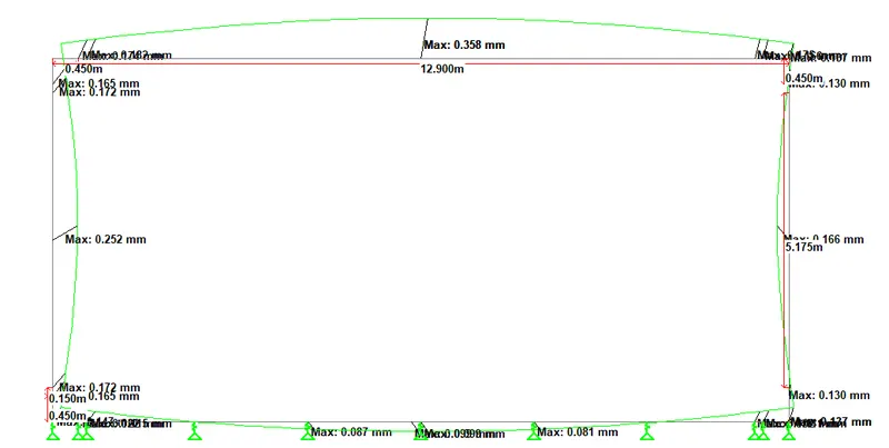
3. Live load surcharge
BM-
SF-
Deflection-
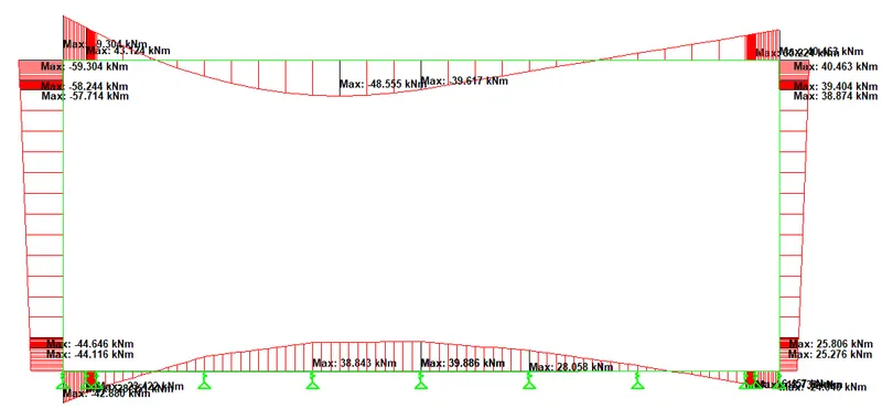
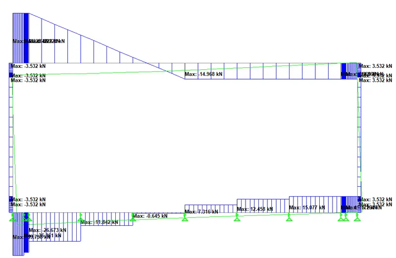
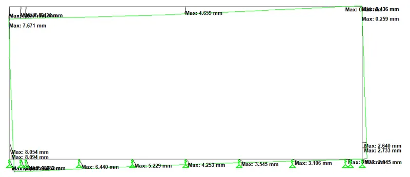
4. 70R load
BM-
SF-
Deflection
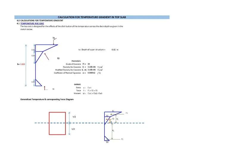
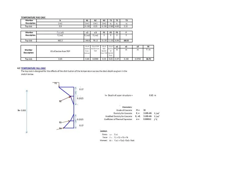
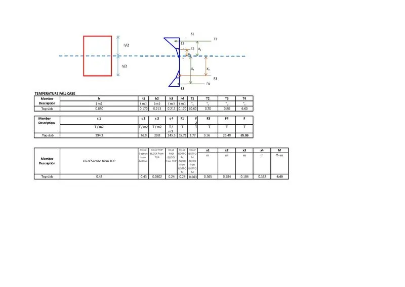
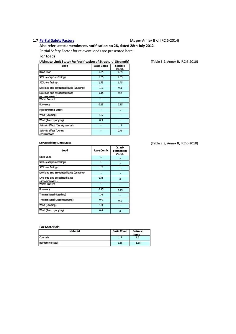
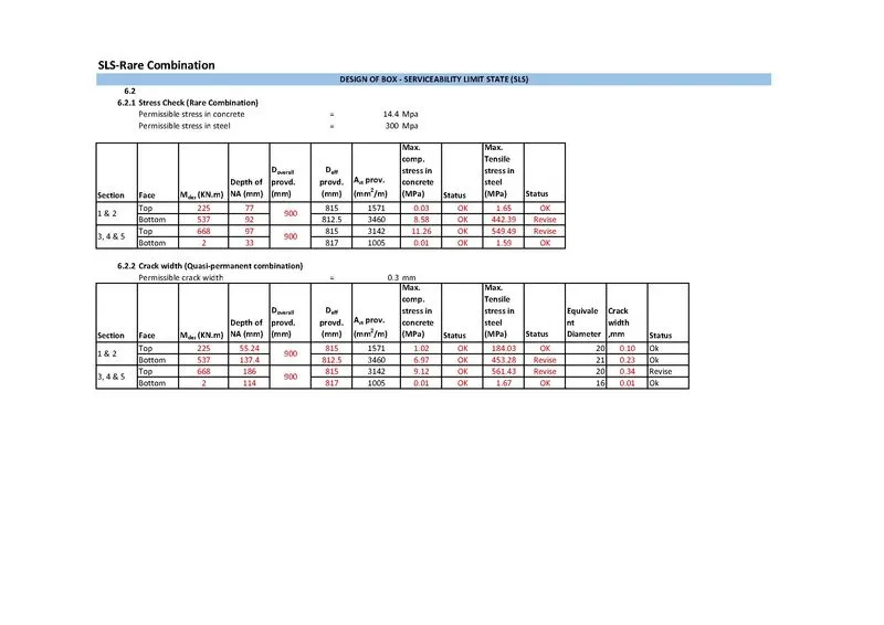
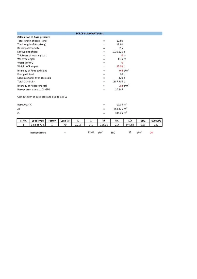
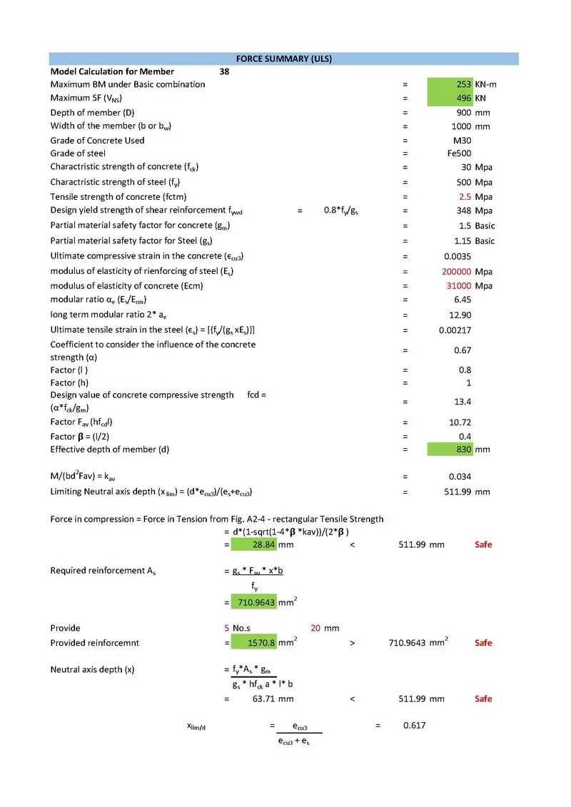
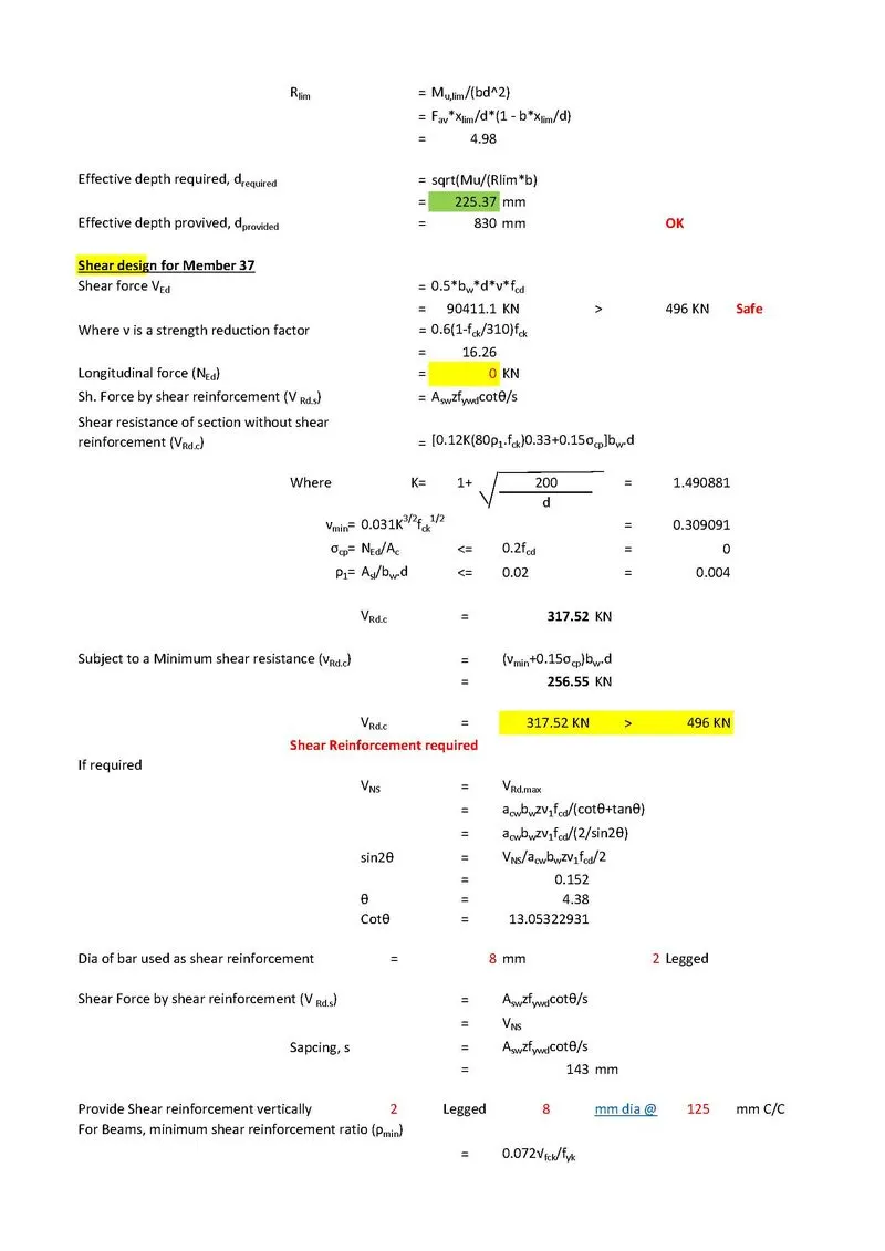
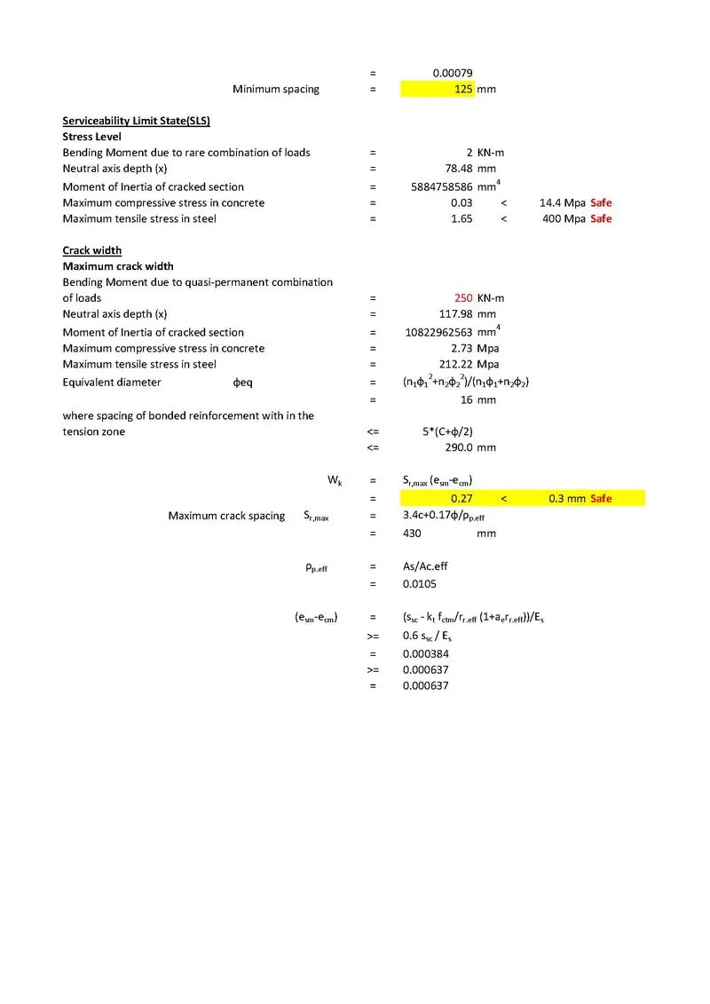
2. Based on the analysis design the members and outline the thought process in selecting the member sizes along with the raft foundation design.
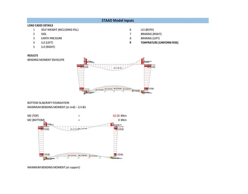
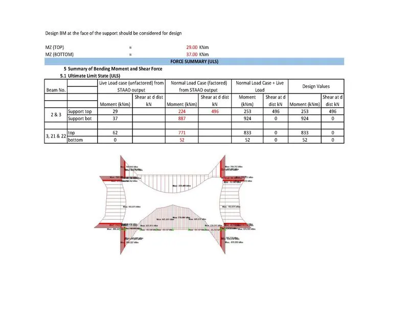
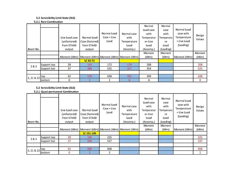
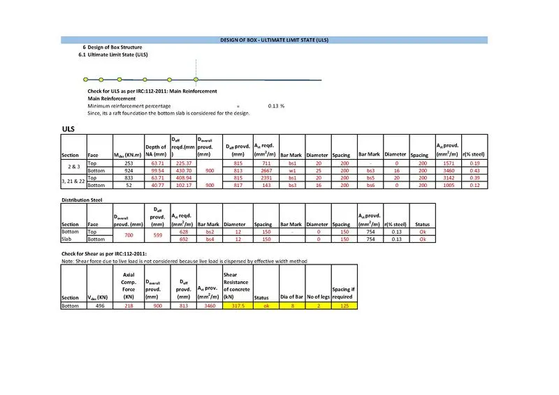
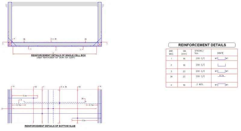
3. Detailing of reinforcement in the base slab.
4. Also, what will be the change in shear in the base slab if there is
a)5 m fill
It is being analyzed by applying the load in Staad pro.
| Height of fill | = | 5 | m | |||
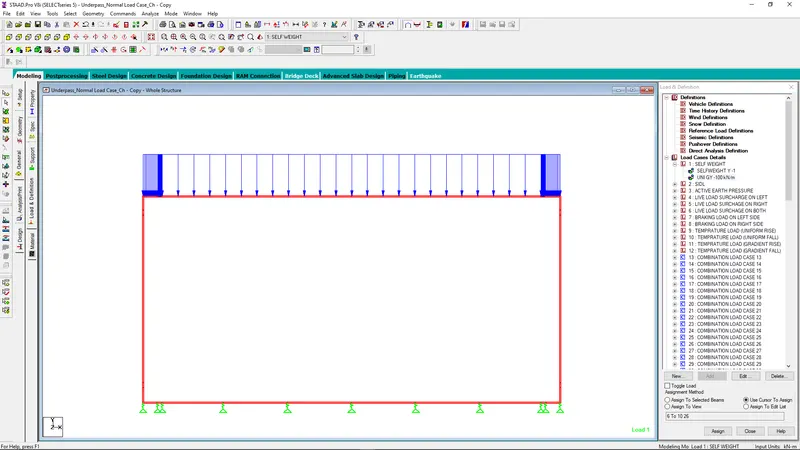
| Load (UDL) on top slab | = | 100.0 | KN/m |
Applying the load
Shear Force Diagram
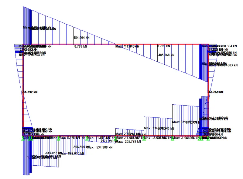
As per the analysis, the maximum shear force for design is = 1102KN
| Maximum SF (VNS) | = | 1102 | KN | ||||||||||||||||||
| Shear design | |||||||||||||||||||||
| Shear force VEd | = | 0.5*bw*d*ν*fcd | |||||||||||||||||||
| = | 90411.1 | KN | > | 1102 KN | Safe | ||||||||||||||||
| Where ν is a strength reduction factor | = | 0.6(1-fck/310)fck | |||||||||||||||||||
| = | 16.26 | ||||||||||||||||||||
| Longitudinal force (NEd) | = | 0 | KN | ||||||||||||||||||
| Sh. Force by shear reinforcement (V Rd.s) | = | Aswzfywdcotθ/s | |||||||||||||||||||
| Shear resistance of section without shear reinforcement (VRd.c) | = | ||||||||||||||||||||
| [0.12K(80ρ1.fck)0.33+0.15σcp]bw.d | |||||||||||||||||||||
| Where | K= |
|
200 | = | 1.490881 | ||||||||||||||||
| d | |||||||||||||||||||||
| νmin= | 0.031K3/2fck1/2 | = | 0.309091 | ||||||||||||||||||
| σcp= | NEd/Ac | <= | 0.2fcd | = | 0 | ||||||||||||||||
| ρ1= | Asl/bw.d | <= | 0.02 | = | 0.004 | ||||||||||||||||
| VRd.c | = | 317.52 | KN | ||||||||||||||||||
| Subject to a Minimum shear resistance (νRd.c) | = | (νmin+0.15σcp)bw.d | |||||||||||||||||||
| = | 256.55 | KN | |||||||||||||||||||
| VRd.c | = | 317.52 KN | > | 1102 KN | |||||||||||||||||
| Shear Reinforcement required | |||||||||||||||||||||
| If required | |||||||||||||||||||||
| VNS | = | VRd.max | |||||||||||||||||||
| = | acwbwzν1fcd/(cotθ+tanθ) | ||||||||||||||||||||
| = | acwbwzν1fcd/(2/sin2θ) | ||||||||||||||||||||
| sin2θ | = | VNS/acwbwzν1fcd/2 | |||||||||||||||||||
| = | 0.338 | ||||||||||||||||||||
| θ | = | 9.89 | |||||||||||||||||||
| Cotθ | = | 5.735258828 | <= 2.5 | >= 1 | |||||||||||||||||
| Dia of bar used as shear reinforcement | = | 12 | mm | 2 | Legged | ||||||||||||||||
| Shear Force by shear reinforcement (V Rd.s) | = | Aswzfywdcotθ/s | |||||||||||||||||||
| = | VNS | ||||||||||||||||||||
| Spacing, s | = | Aswzfywdcotθ/s | |||||||||||||||||||
| = | 145 | mm | |||||||||||||||||||
| Provide Shear reinforcement vertically | 2 | Legged | 12 | mm dia @ | 125 | mm C/C | |||||||||||||||
b)1 m fill on top of the bridge:
| Maximum SF (VNS) | = | 497 | KN | ||||||||||||||||||
| Shear design | |||||||||||||||||||||
| Shear force VEd | = | 0.5*bw*d*ν*fcd | |||||||||||||||||||
| = | 90411.1 | KN | > | 497 KN | Safe | ||||||||||||||||
| Where ν is a strength reduction factor | = | 0.6(1-fck/310)fck | |||||||||||||||||||
| = | 16.26 | ||||||||||||||||||||
| Longitudinal force (NEd) | = | 0 | KN | ||||||||||||||||||
| Sh. Force by shear reinforcement (V Rd.s) | = | Aswzfywdcotθ/s | |||||||||||||||||||
| Shear resistance of section without shear reinforcement (VRd.c) | = | ||||||||||||||||||||
| [0.12K(80ρ1.fck)0.33+0.15σcp]bw.d | |||||||||||||||||||||
| Where | K= |
|
200 | = | 1.490881 | ||||||||||||||||
| d | |||||||||||||||||||||
| νmin= | 0.031K3/2fck1/2 | = | 0.309091 | ||||||||||||||||||
| σcp= | NEd/Ac | <= | 0.2fcd | = | 0 | ||||||||||||||||
| ρ1= | Asl/bw.d | <= | 0.02 | = | 0.004 | ||||||||||||||||
| VRd.c | = | 317.52 | KN | ||||||||||||||||||
| Subject to a Minimum shear resistance (νRd.c) | = | (νmin+0.15σcp)bw.d | |||||||||||||||||||
| = | 256.55 | KN | |||||||||||||||||||
| VRd.c | = | 317.52 KN | > | 497 KN | |||||||||||||||||
| Shear Reinforcement required | |||||||||||||||||||||
| If required | |||||||||||||||||||||
| VNS | = | VRd.max | |||||||||||||||||||
| = | acwbwzν1fcd/(cotθ+tanθ) | ||||||||||||||||||||
| = | acwbwzν1fcd/(2/sin2θ) | ||||||||||||||||||||
| sin2θ | = | VNS/acwbwzν1fcd/2 | |||||||||||||||||||
| = | 0.153 | ||||||||||||||||||||
| θ | = | 4.39 | |||||||||||||||||||
| Cotθ | = | 13.02665484 | <= 2.5 | >= 1 | |||||||||||||||||
| Dia of the bar used as shear reinforcement | = | 8 | mm | 2 | Legged | ||||||||||||||||
| Shear Force by shear reinforcement (V Rd.s) | = | Aswzfywdcotθ/s | |||||||||||||||||||
| = | VNS | ||||||||||||||||||||
| Spacing, s | = | Aswzfywdcotθ/s | |||||||||||||||||||
| = | 142 | mm | |||||||||||||||||||
| Provide Shear reinforcement vertically | 2 | Legged | 8 | mm dia @ | 125 | mm C/C | |||||||||||||||