Week 6 Challenge
To calculate the pipe loads for the bridge, we need to consider the weight of the pipes and the water flowing through them.
1. Weight of 700mm diameter NB DI pipe:
The weight of the pipe can be calculated using the formula: Weight = Volume x Density where, Volume = π/4 x (D^2 - d^2) x L D = 700mm (outer diameter) d = 672mm (inner diameter) L = length of pipe = 24m Density of DI pipe = 7850 kg/m^3 (approx.)
Substituting the values, we get: Volume = π/4 x (0.7^2 - 0.672^2) x 24 = 1.438 m^3 Weight = Volume x Density = 1.438 x 7850 = 11,285.3 kg
Therefore, the weight of the 700mm diameter NB DI pipe is 11,285.3 kg.
2. Weight of 200mm diameter NB DI pipe:
Using the same formula as above, we can calculate the weight of the 200mm diameter NB DI pipe: D = 200mm (outer diameter) d = 182mm (inner diameter) L = 24m Density of DI pipe = 7850 kg/m^3 (approx.)
Volume = π/4 x (0.2^2 - 0.182^2) x 24 = 0.124 m^3 Weight = Volume x Density = 0.124 x 7850 = 973.4 kg
Therefore, the weight of the 200mm diameter NB DI pipe is 973.4 kg.
3. Water flowing through the pipes:
To calculate the water load, we need to consider the maximum flow rate through the pipes and the density of water. Let's assume a flow rate of 1 m^3/s through each pipe.
Density of water = 1000 kg/m^3 Volume of water flowing through each pipe = 1 m^3/s x 24 s = 24 m^3 Weight of water flowing through each pipe = Volume x Density = 24 x 1000 = 24,000 kg
Therefore, the water load for each pipe is 24,000 kg.
The total load on the bridge due to pipes: Weight of 700mm NB DI pipe = 11,285.3 kg Weight of 200mm NB DI pipe = 973.4 kg Water load for each pipe = 24,000 kg
Total load = (11,285.3 + 973.4 + 24,000) x 2 = 73,517.4 kg
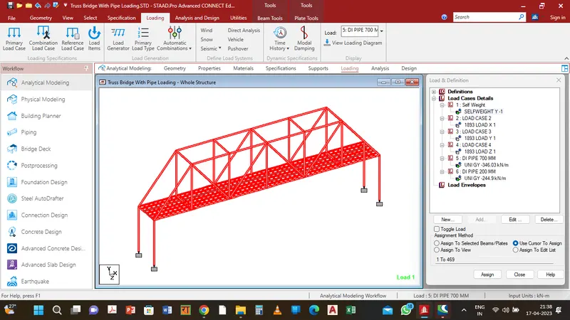
We can now apply this load in Staad. pro for analysis of the bridge.
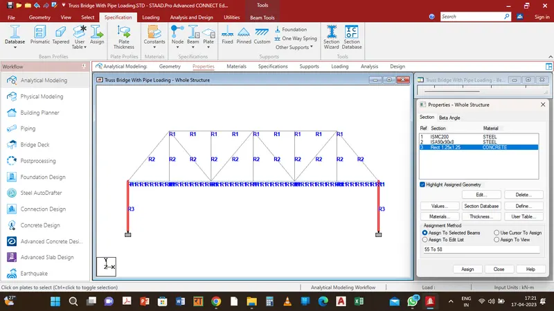
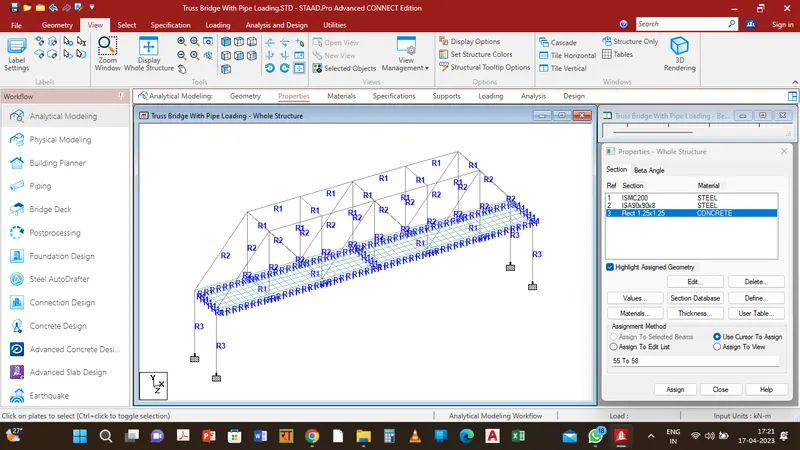
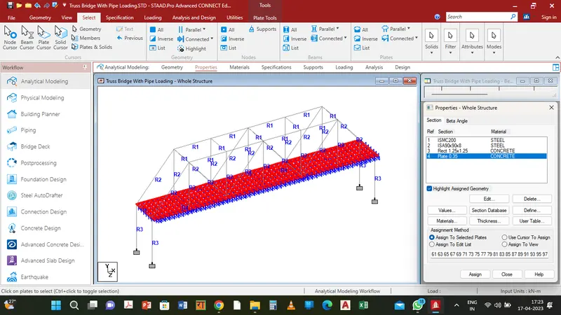
1. Define the properties of the bridge structure, including its dimensions, material properties, and section properties.
2. Create the two pipe elements in the model. Use the "DI pipe" section property to define the sections for the pipes.
3. Assign the properties and geometry of the pipes to their respective elements.
4. Define the loads to be applied to the structure. In this case, we will apply a concentrated load at the center of each pipe.
5. To apply the concentrated load, go to the "Load" tab and select "Concentrated Load".
6. In the dialog box that appears, specify the load value as the weight of the pipe and water load for each pipe.
7. Specify the location of the load as the center of each pipe. To do this, use the "X" coordinate and "Z" coordinate to position the load at the center of the pipe.
8. Apply the loads to the appropriate pipe element using the "Element" option.
9. Repeat this process for the other pipe element.
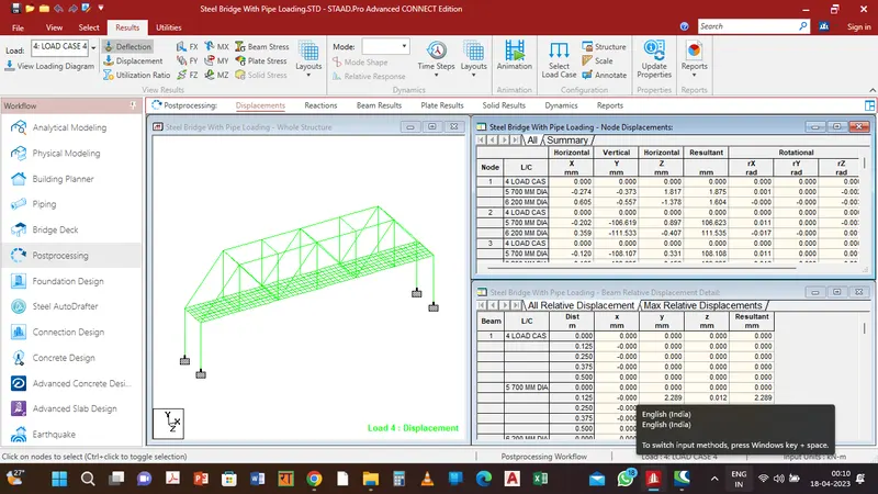
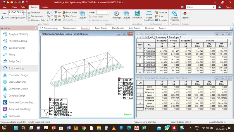
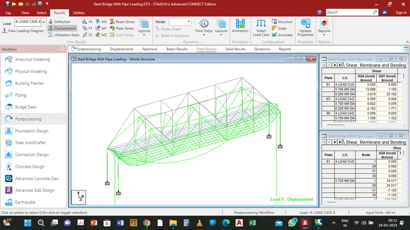
10. Save the model and Run an analysis of the bridge to determine its response to the applied loads.
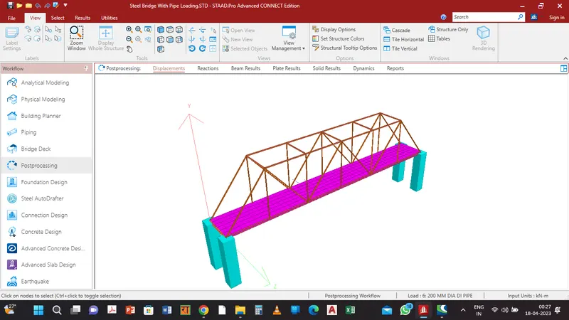
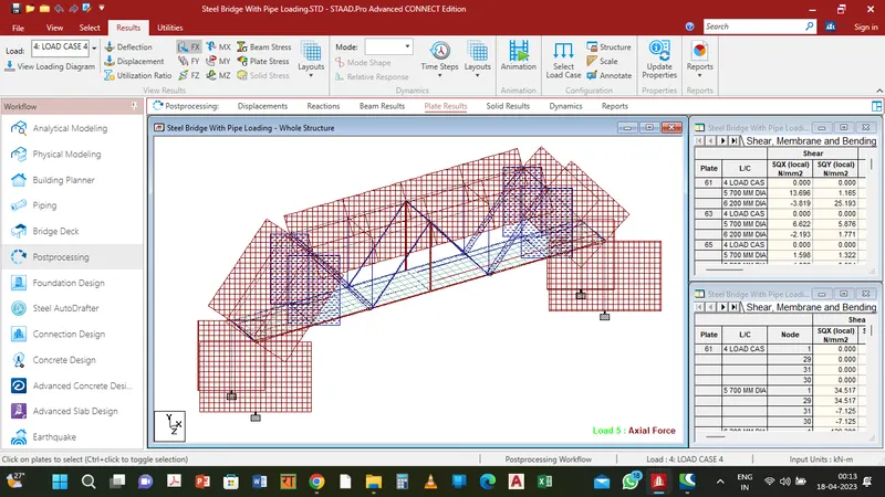
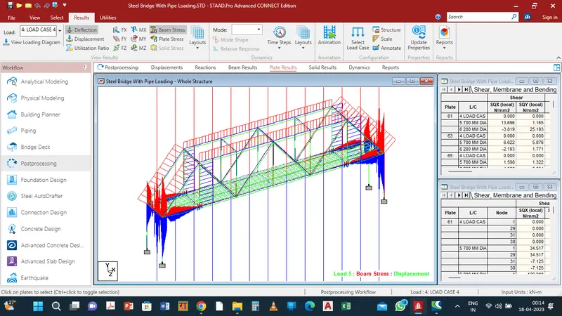
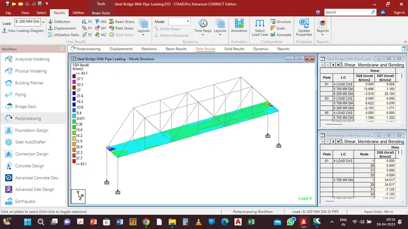
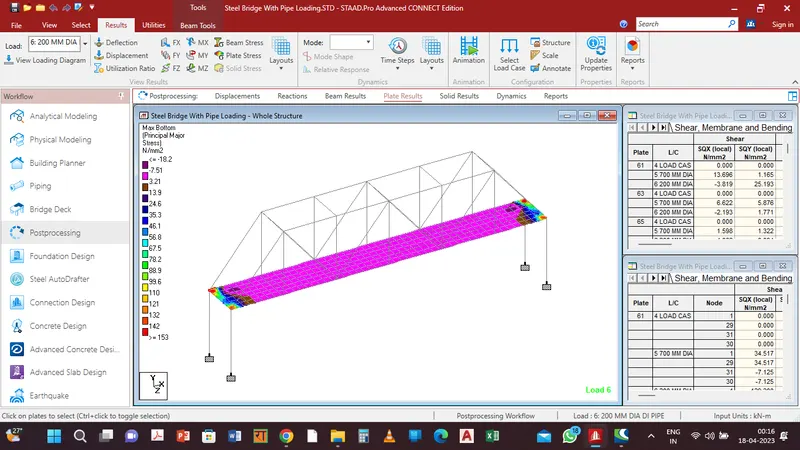
The Bridge Model with Analysis are attached below and the Analysis PDF File is also attached: