Week 6 Challenge
aim-: calculate two pipe load on a bridge and analysis this load in staddpro
given data-:
width of bridge=3m
pier to pier distance as from figure=24m
dia of pipe P1& P2= 700mm & 500mm
first calculation of pipe load-:
Let us say pipe type k9class
1. self wt of DI pipe for 700 mm dia no classification so let us say 600mm dia is 217.19kg/m=.21719kn/m
for span of 24m = 0.21719*24= 5.21256kn
live load of DI pipe i.e load due to water= area* unit wt=`pi`0.*0.3*10=2.82kn/m
total load acting on bridge= 5.21256+2.82=8.04kn/m
simillary for 200mm dia pipe class k9 type wt= 45.28 kg/m=0.04528kn/m
for 24m span = 0.04528*24=1.08672kn
live load on pipe due top water= pi*0.1*0.1*10=0.3142kn/m
total wt on bridge= 1.08672+0.3142=1.401kn/m
this two pipe load is applied on superstructer of bridge as UDL
apply this load in stadd pro
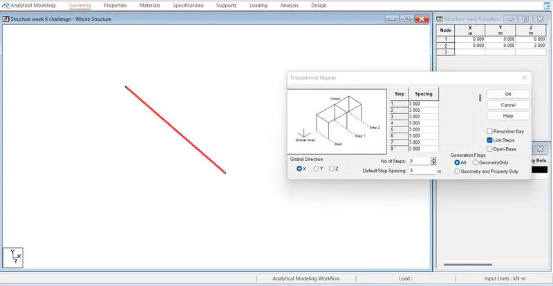
Create a node at origin X=0,Y=0,Z=0 , from geometry add beam as bridge width 3m and from translition repeat command in X dir with 8 step at spacing of 3m as shown in given figure the span length of bridge is 24m
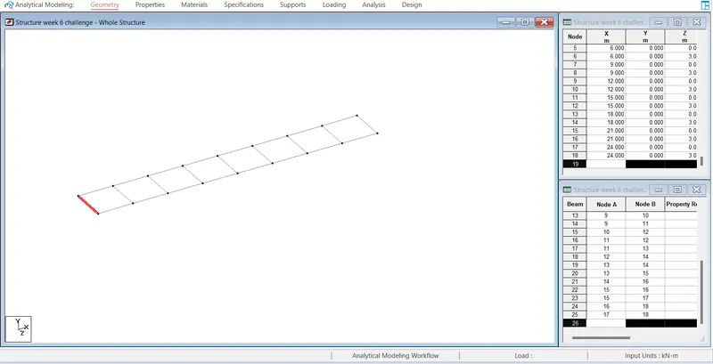
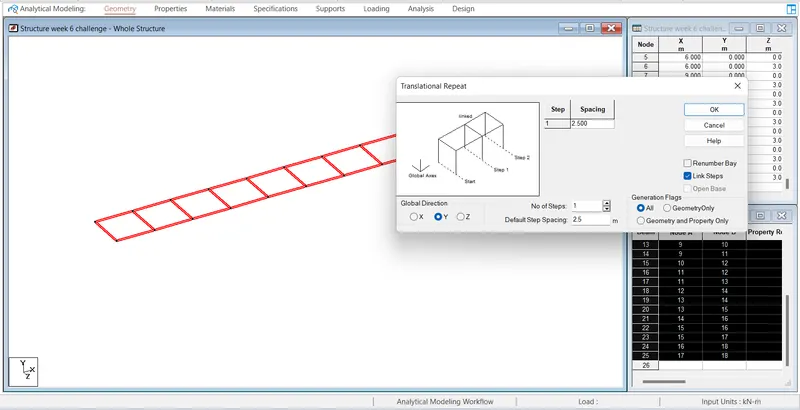
As shown in given figure it is steel structure and a truss bridge so using translation repeat @Y dir of ht of 2.5m with linked step create same structure
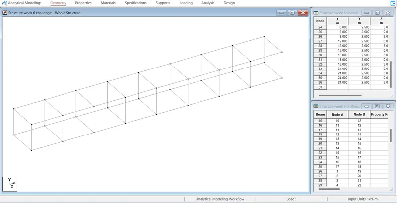
now add the diagonal member of truss structure and insert node at top of mid point width of bridge
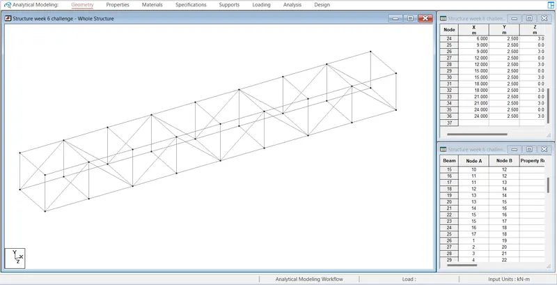
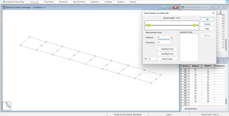
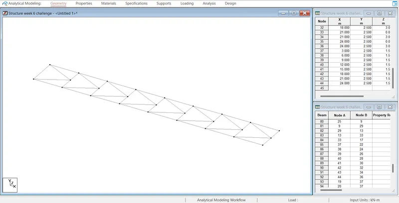
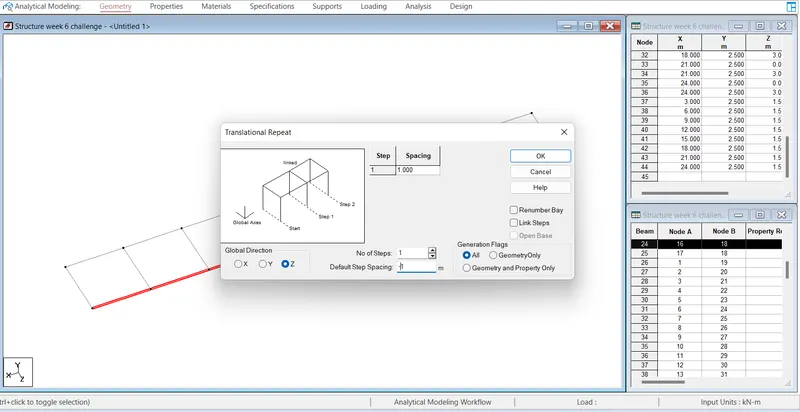
now form figure add beamin-z direction by same translitional repeat command @ 1m as 700mm dia pia is @ 1m from end of beam simillarly 200 @ 0.640 and two other beam @same distance 0.640 but at +z dir
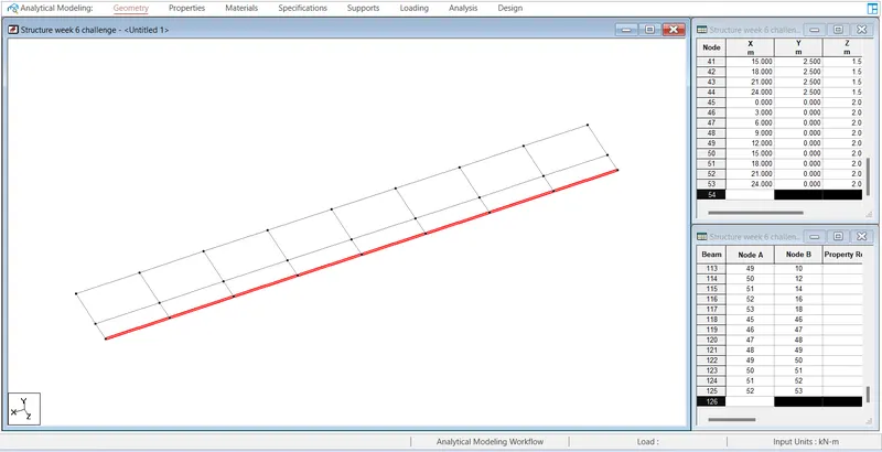
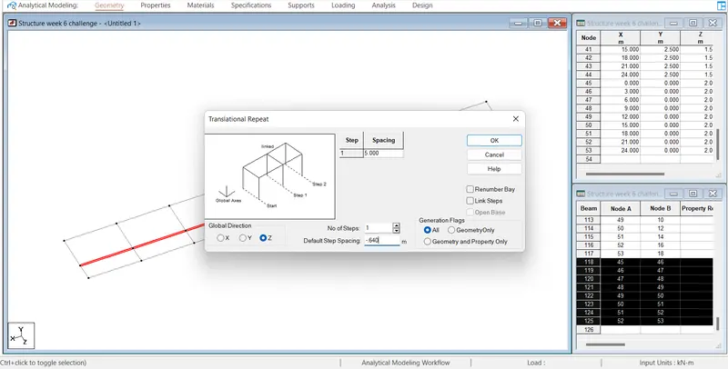
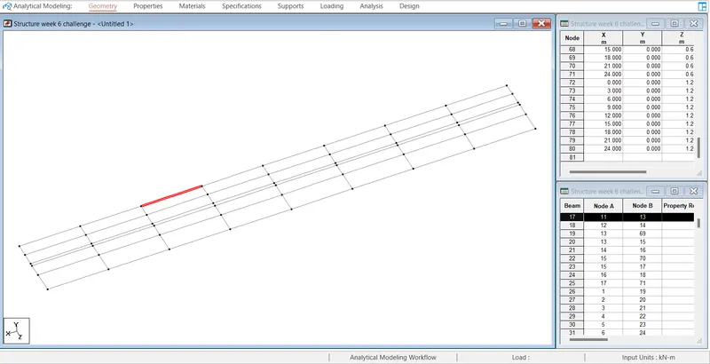
the whole structure after introducing whole member are as shown below
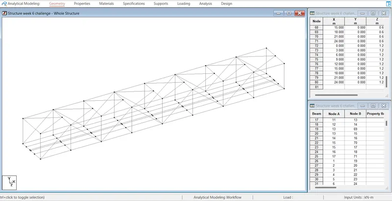
now define the properties for the member as shown in the given diagram
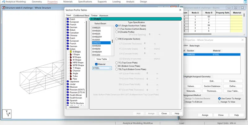
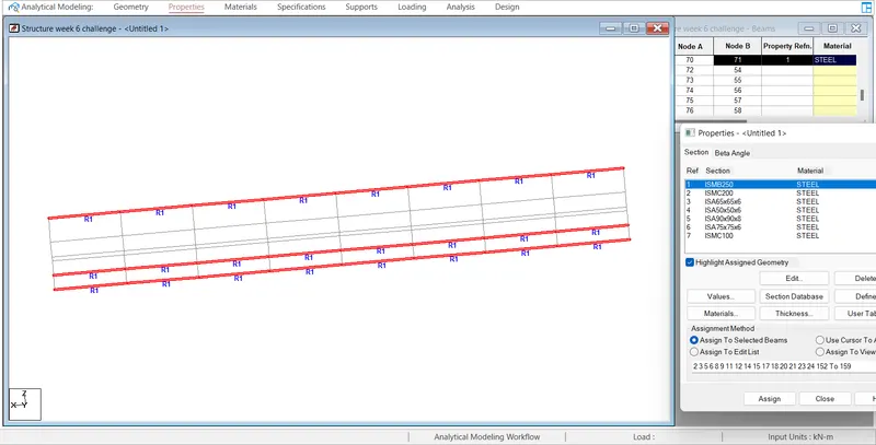
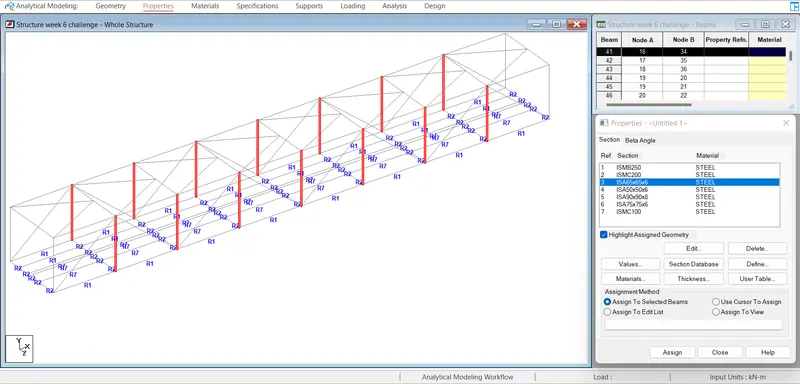
Assinging the property bottom beam ISMB 2500 verticle member as ISA 75*75*6
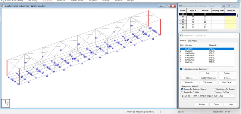
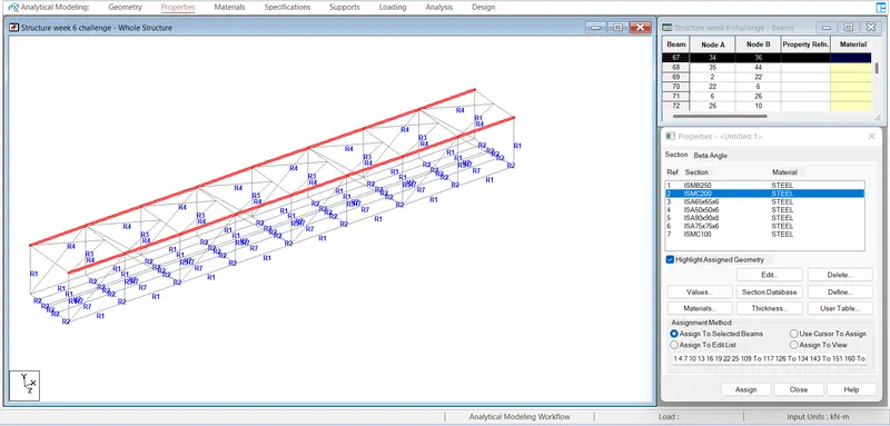
end of the verticle member ISMC 200, introduced the properties to the angle member as ISA 65*65*6 and top angle member as ISA 50*50*6
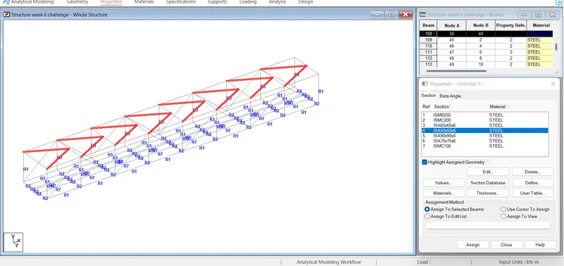
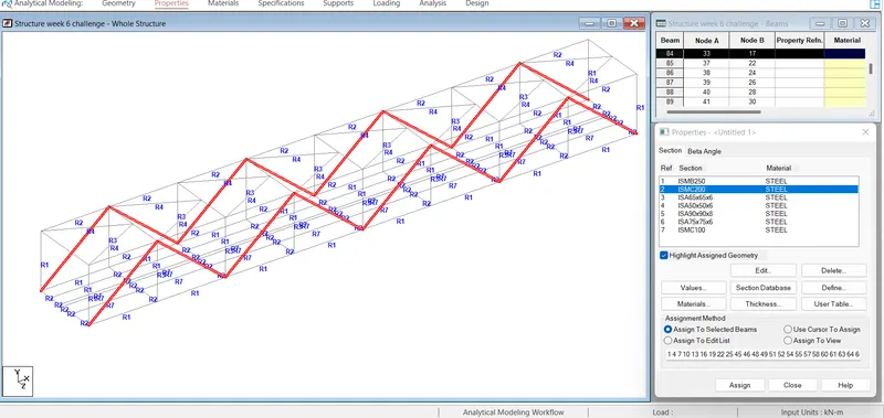
assisn property to top channel as ISA 90*90*8
after assinging the whole member properties creat a node @ -Y dir of ht and give fixed support to the pier
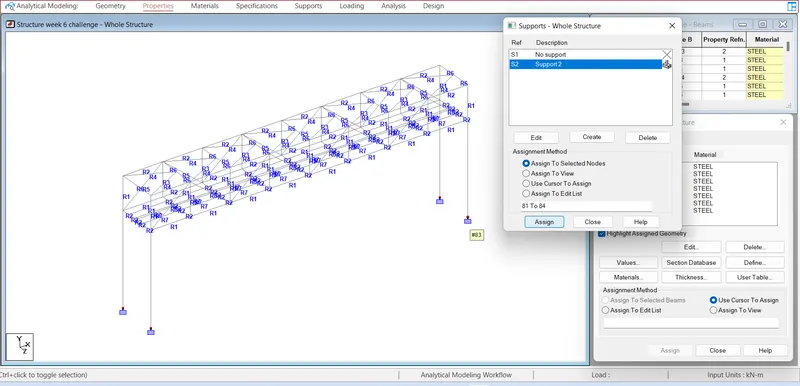
and assign to property as circular of dia 1.2m
now add first load case as K9 DI pipe of 600mm dia simillarly for 200mm dia pipe and define W1 for 600mm dia and w1 for 200mm dia pipe as follow the loading diagram is also shown as folloe after assinging the load by selecting the beam member @ 1m and 0.640m
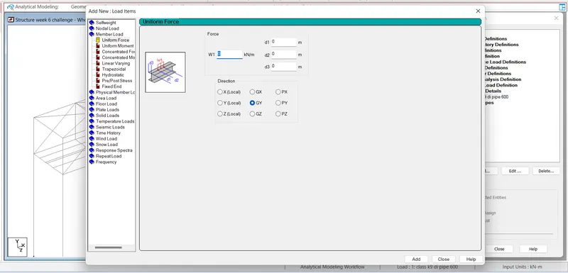
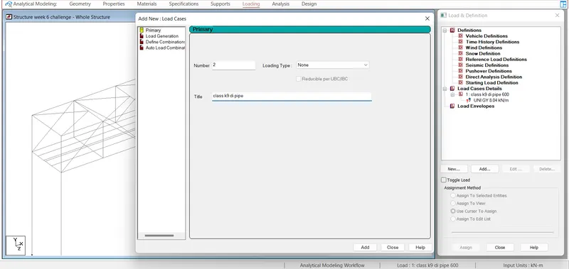
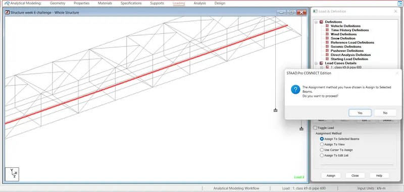
Loading diagram @ 200mm dia DI pipe
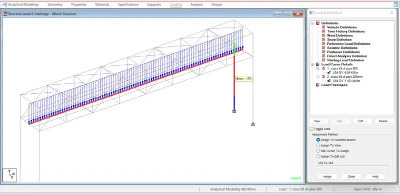
loading diagram @ 200mm dia pipe
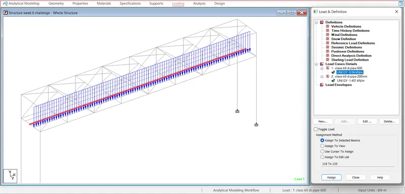
now after defining member property and load case and the value of load run the ananlysis part
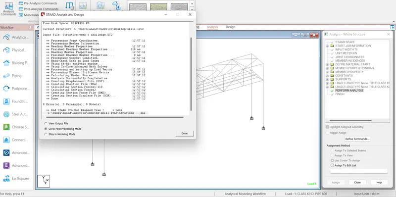
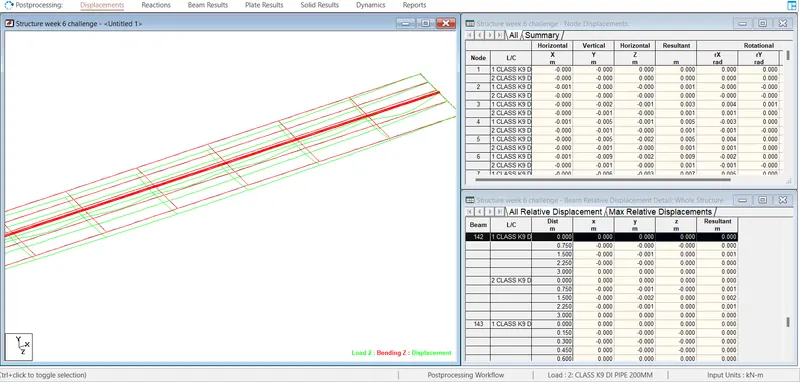
after ananlysis part the deflection of structure is as shown below
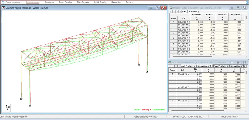
after selecting the loaded member the deflection of loaded beam as below
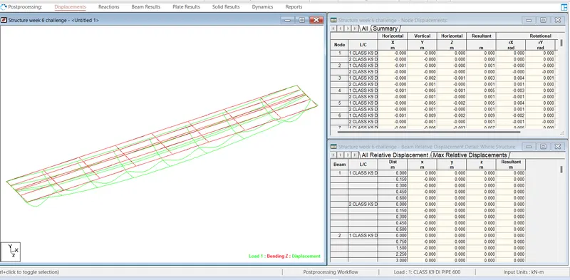
the report of member deflection moment at -z -y as show below
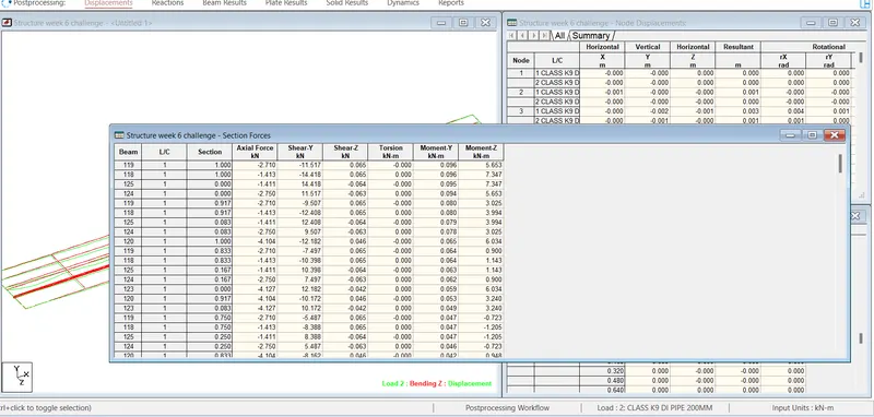
the maximum moment @ -Z of 600mm and 200mm dia pipe is 5.653knm & 1.265knm respectively