To Perform the Tensile Test on the Solid Block using different Element Formulation
AIM -
To Perform the Tensile Test on the Solid BLock & Calculate for the Stretch Ratio by comparing the Element Formulation for Ogden Material
OBJECTIVE -
- Create a block of 10mmx10mmx10mm dimension with 10 elements for each direction and use the material card attached (Ogden_Material.k) that is representative of the material properties from the above figure.
- Use appropriate boundary conditions to simulate tensile behavior for the model and finally compare the results from your simulation to the plot above up to stretch ratio 5. Only the uniaxial plot is to be compared.
- Compare the results for the simulation using ELFORM = 1, 2, -1, -2
PROCEDURE -
1. CREATING THE FEA MODEL
Using the geometry module solid block is created as shown below. The dimension of the box are provided as below,
x1 = 0, x2 = 10
y1 = 0, y2 = 10
z1 = 0, z2 = 10
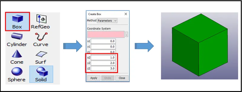
Figure 1. Creating the Solid Block
2. CREATING THE SOLID MESH.
To create a mesh the user uses the Mesh Module and selects the solid mesh as a sub-type. Element size is kept as 1 and volume is selected and the mesh is generated on the block as shown below.
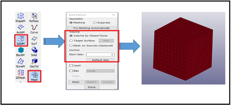
Figure 2. Creating the Solid Mesh
3. CREATING *MAT Material Card
This is also Material Type 77. This material model provides the Ogden [1984] rubber model combined optionally with linear viscoelasticity as outlined by Christensen [1980].
The parameter is passed based on the LS-DYNA Manual.
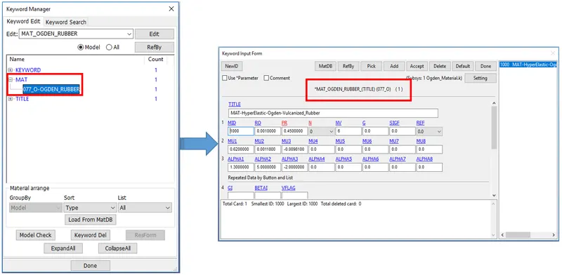
Figure 3. *MAT Card Definition
After creating the material card it is assigned to the part in the keyword.
4. CREATING *SECTION Card
In this section, the element formulation, integration rule, nodal thicknesses, and cross-sectional properties are defined.
Section card is created to simulate the solid block for 4 different types of element formulation. Only one keyword file is created for ELFORM 1 and the remaining formulations are created using the same c=keyword file using the notepad++ which is very easier to create once the main keyword file is ready.
The solid block section card is created with the element formulation as ELFORM_1 which is basically the default formulation for constant stress solid element used for the solid element. Other formulations used for this model with their description is mentioned below,
ELFORM:=Element formulation options:
EQ.-2: fully integrated S/R solid intended for elements with poor aspect ratio, accurate formulation.
EQ.-1: fully integrated S/R solid intended for elements with poor aspect ratio, efficient formulation.
EQ.1: constant stress solid element (default),
EQ.2: fully integrated S/R solid,
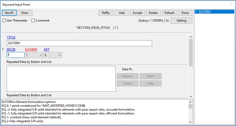
Figure 4. *SECTION Card Definition
After creating the section card it is assigned to the part in the keyword.
5. Creating *CONTROL Card
The keyword control card is used to control the type of simulation. The Control Termination card is however mandatory to define as it helots the solver to stop at the user's will.
As the user see that this block is very small and there will not be much more deformation in the block even after applying some load and displacement boundary conditions. So the user decides to simulate the model with the implicit method.
For the user select the required control card for implicit analysis.
*CONTROL_IMPLICIT_GENERAL
Purpose: Activates implicit analysis and defines associated control parameters. This keyword is required for all implicit analyses.
Using the *CONTROL_IMPLICIT_GENERAL keyword, a simulation may be flagged to run entirely in implicit mode.
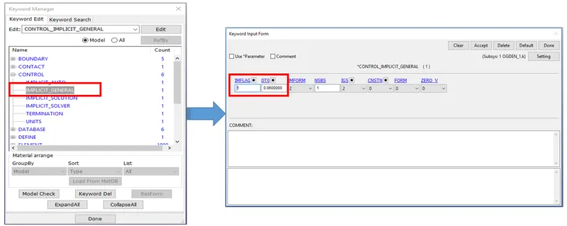
Figure 5. *CONTROL IMPLICIT GENERAL Card Definition
IMFLAG Implicit/Explicit analysis type flag :
EQ.0: explicit analysis
EQ.1: implicit analysis
By switching the flag value to 1 the analysis will run in the implicit mode. The value of DT is determined by the formulation as below,
`dT = [Termination time] / [100]`
For this model, the termination time is decided as 6ms so the dt = 0.06 ms
*CONTROL_IMPLICIT_AUTO
Purpose: Defined parameters for automatic time step control during implicit analysis.
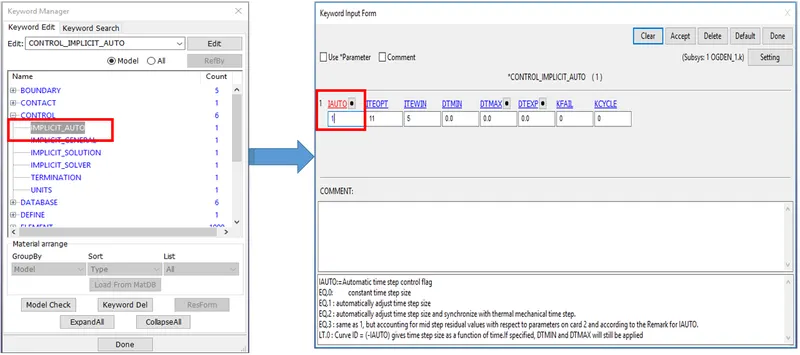
Figure 6. *CONTROL IMPLICIT AUTO Card Definition
IAUTO = 1 controls the time step automatically.
*CONTROL_IMPLICIT_SOLUTION
Purpose: These optional cards applied for implicit calculations. Used these cards to specify whether a linear or nonlinear solution is desired.
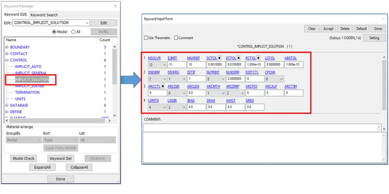
Figure 7. *CONTROL IMPLICIT SOLUTION Card Definition
*CONTROL_IMPLICIT_SOLVER
Purpose: These optional cards applied for implicit calculations. The linear equation solver performs the CPU-intensive stiffness matrix solution.
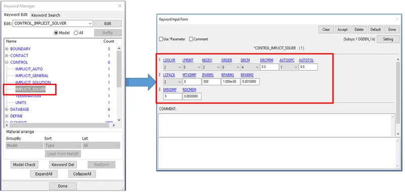
Figure 8. *CONTROL IMPLICIT SOLVER Card Definition
*CONTROL_TERMINATION
This keyword is used to specify the solver when to end the simulation. This is mandatory to define the termination card.
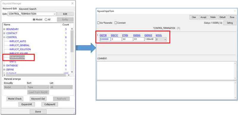
Figure 9. *CONTROL TERMINITIION Card Definition
*CONTROL_UNIT
Purpose: This card is used to specify the user units for the current keyword input deck.
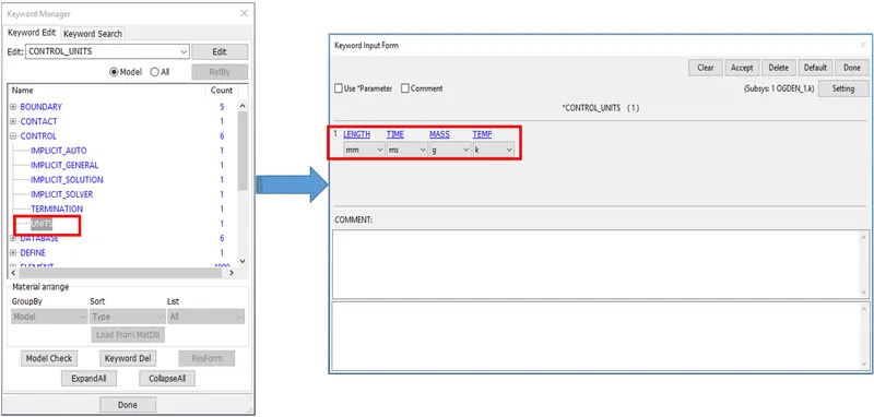
Figure 10. *CONTROL TERMINITIION Card Definition
6. CREATING *CONTACT Card
The keyword *CONTACT provides a way of treating interaction between disjoint parts.
The user selects the Automatic Single Surface Contact as there only a single part present in the model.
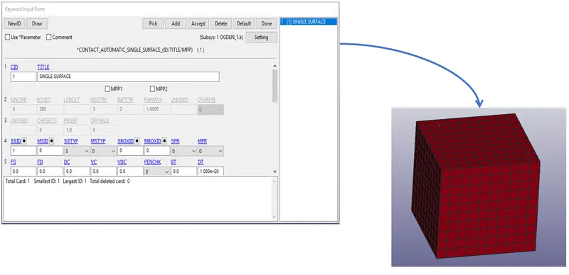
Figure 11. *CONTACT Card Definition
7. Boundary Condition
As the Tensile test is to be performed on the block the boundary condition is an important concept. One end of the box is fixed using the SPC set in all three directions now by one as shown below. Also, the prescribed motion is applied at the other end to visualize the tensile loading.
Boundary Conditions are applied in such a way that the model should be able to reduce in the cross-section from one end to the other end when the displacement is applied at the other end opposite to the fixed end.
*PESCRIBED_MOTION_SET
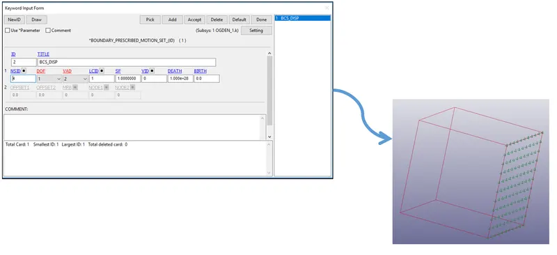
Figure 12. *PRESCRIBED MOTION BCS
Motion is provided by defining a displacement curve which is taking care of the tensile loading of the block.
*SPC
#1 - X Direction Translation and All Rotational Movement Locked for the left side nodes.
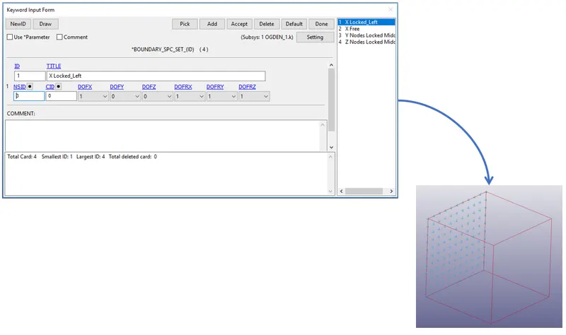
Figure 13. *SPC for Left Side Nodes
#2 - All nodes except the nodes on the left side are constrained in All Rotational Movement
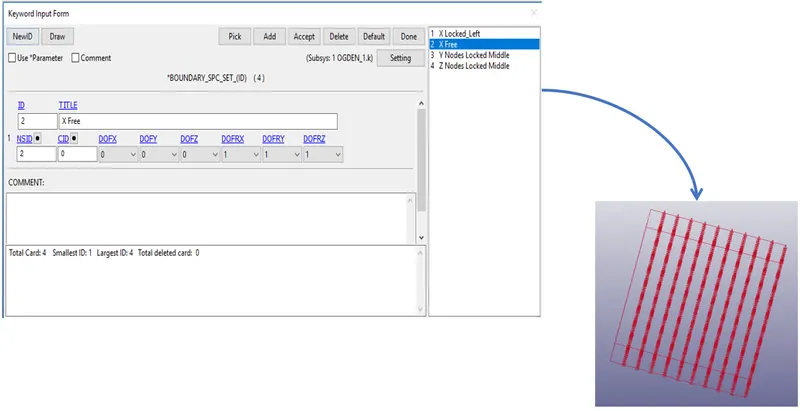
Figure 14. *SPC for Right Side Nodes
#3 - Nodes on the left side of the block constrained in the Y direction at the middle to restrict the lateral movement.
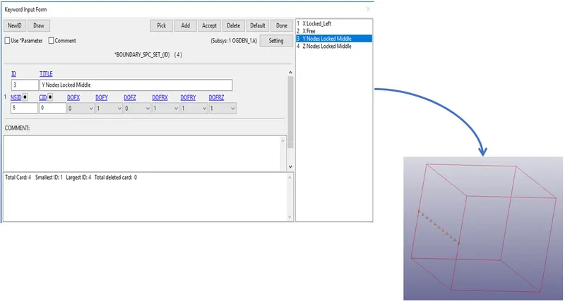
Figure 15. *SPC for Middle Nodes Y Direction
#4 - Nodes on the left side of the block constrained in the Z direction at the middle to restrict the lateral movement.
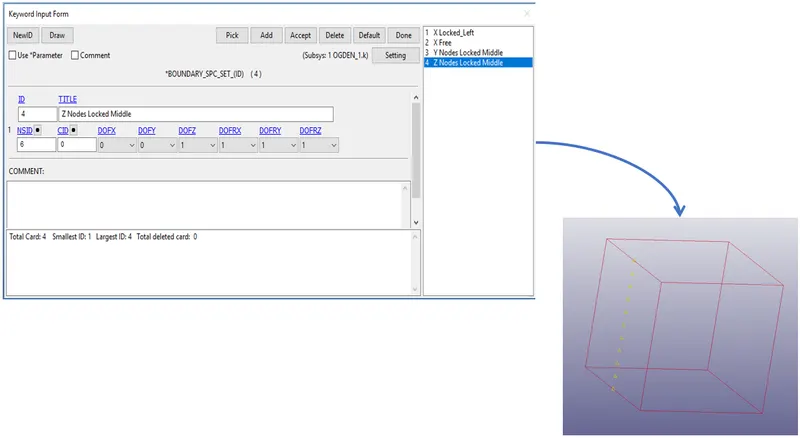
Figure 16. *SPC for Middle Nodes Z Direction
8. Curve Data for Displacement
Before imposing the displacement for the prescribed motion set the user makes sure the displacement is enough that it will reach the value of stretch ratio as 5 at the end of the simulation.
This is found by using the below relation,
Stretch Ratio `λ = 1 + ε_e` and `ε_e = (delta l)/ (l)`
For a minimum stretch ratio of 5, the minimum change in change should be 40 mm. So based on this correlation the displacement value of 50 mm is taken for the safe side.
Displacement data is provided as below,
0 ms - 0 mm
6 ms - 50 mm
10 ms - 50 mm
The curve is extended beyond the termination time to run the simulation smoothly with disturbance in the result.
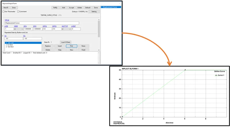
Figure 17. *Displacement Curve
8. CREATING *DATABASE Card
A database card is created to notice the results of the simulation at a specific time step.
Cards created are,
I. ASCII card which records the secforc, rcforce, glsat, nodout, etc.
II. Binary D3Plot which is used to plot the energy's
III. Extent Binary - The BINARY option of *DATABASE_EXTENT applies to the binary databases d3plot, d3thdt, and d3part.
IV. HISTORY SOLID SET to measure the nodal parameters
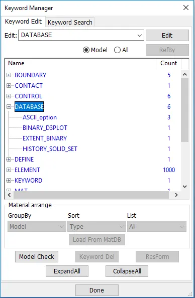
Figure 18. *Database Output Request
9. Post Processing
I. Ran the keyword file using the LS Run Manager. Note down the termination to be normal.
II. Opened the LSPP to check the file has captured all the results and plots properly.
III. Checked for all the required animation files.
IV. Generated the Stress and Strain Contour animation.
V. Using the plot option one by one the history of 1 particular node is plotted for Stress and Strain.
Note - This Stress and Strain are true stress and true strain.
The user determines the Engineering Stress and Stress using the below method.
True Stress `(σ_(true)) = σ_(engg) * ( 1 + ε_(engg))`
Therefore,
`σ_(engg) = (σ_(true)) / ( 1 + ε_(engg))`
Similarly, `ε_(true)` = `ln (1 + ε_(engg))` ---> `ε_(engg)` = `e_^(ε_true) - 1`
VI. Using the above relations the value for Engineering Stress and Strain is tabulated in the table form.
`λ = 1 + ε_e` and tabulated the result.
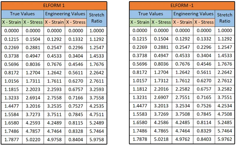
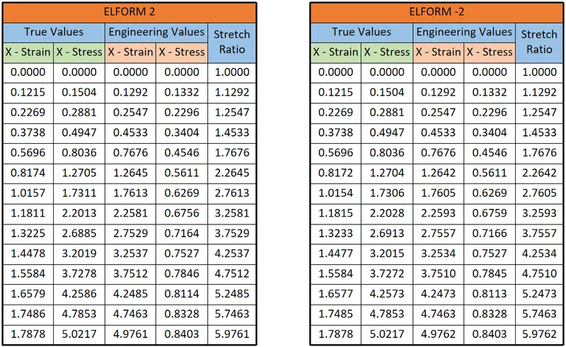
Figure 19. *Tabulated Values for True & Engineering Stress & Strain
VII. Graph is plotted using the above-tabulated data.
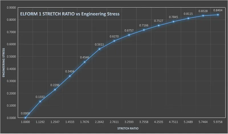
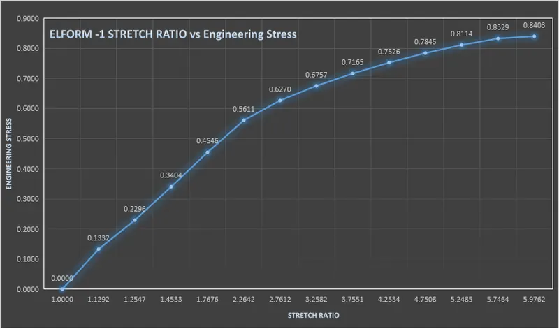
Figure 20. - STRETCH RATIO ELFORM _1 Figure 21 - STRETCH RATIO ELFORM_-1
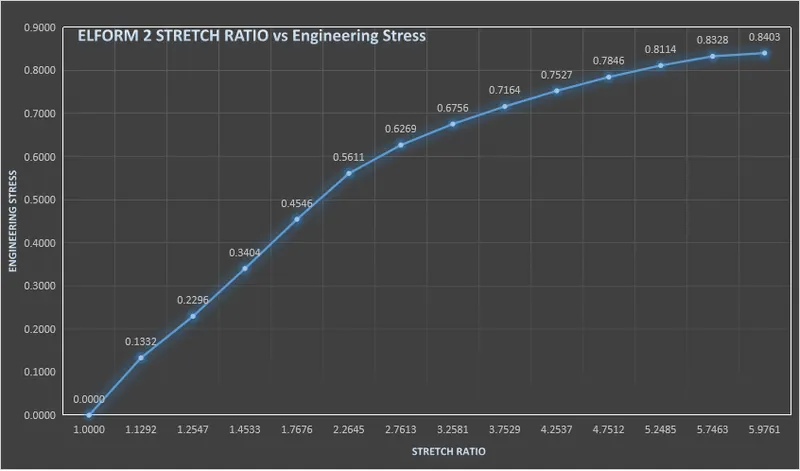
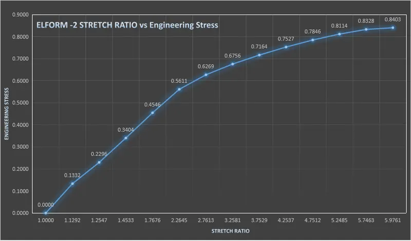
Figure 22. - STRETCH RATIO ELFORM _2 Figure 23. - STRETCH RATIO ELFORM_-2
Stress & Strain Contour for ELFORM
i. ELFORM 1
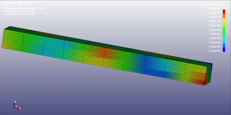
Figure 24. Von Mises Stress ELFORM 1
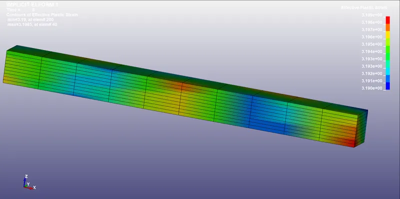
Figure 25. Effective Plastic Strain ELFORM 1
ii. ELFORM -1
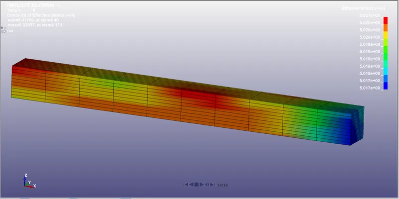
Figure 26. Von Mises Stress ELFORM -1
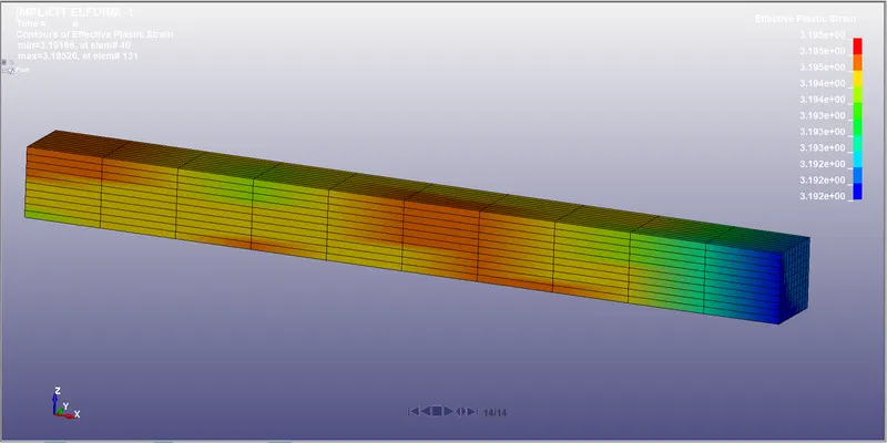
Figure 27. Effective Plastic Strain ELFORM -1
iii. ELFORM 2
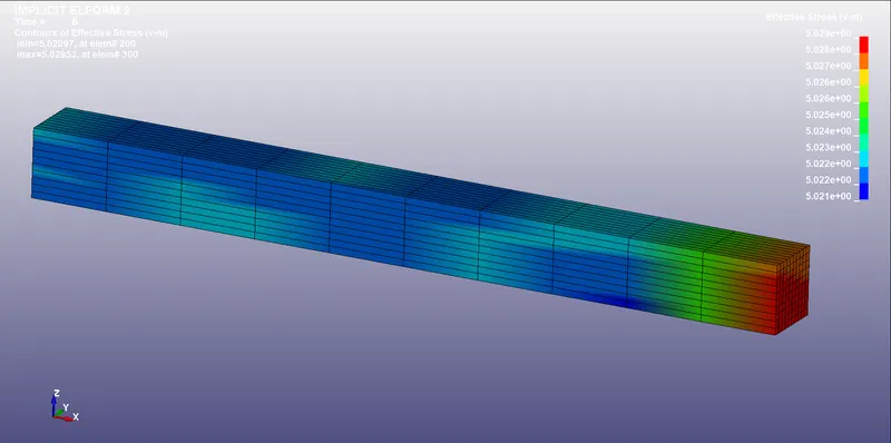
Figure 28. Von Mises Stress ELFORM 2
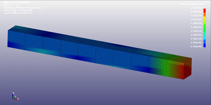
Figure 29. Effective Plastic Strain ELFORM 2
iv. ELFORM -2
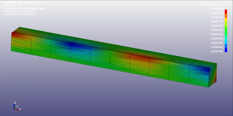
Figure 30. Von Mises Stress ELFORM -2
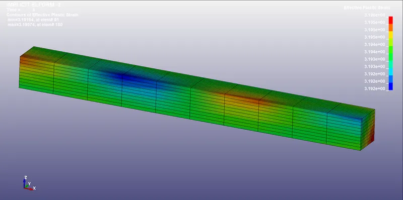
Figure 31. Effective Plastic Strain ELFORM -2
CONCLUSION -
Successfully compared the results of the tensile test on the solid block and compared the results in the tabulated form from the Stress vs Stain for True and Engineering Values along with their equivalent Stretch Ratio.