Week-6 Calculate the Stretch Ratio by comparing the ELFORM (-2,-1,1,2) with Ogden_Material Model.
AIM: To create a Solid meshed block that has 10*10*10mm of length in which considering Hyperelastic material is assigned with different element forms as -2,-1,1,2.
Procedure:
I) Create a Solid mesh element of 10*10*10mm.
II) Constrain the nodes in which to arrest the motion in that direction.
III) Create a set of nodes to constrain.
IV) Assign the material for the model.
V) Assign the section for the model.
VI) Considering the simulation is going to take part in terms of the implicit method.
VII) Check for the model, for any errors in it.
VIII) Run the LS-Run, to run the post-processing.
IX) Then Run the Post-processor to run the LS-Dyna simulation.
Solid Mesh:
To create a Solid mesh in LS-DYNA,
Mesh -> Shape Mesher -> Assign the X, Y, and Z values as 10 -> Click create
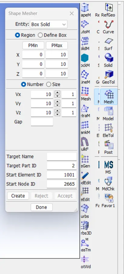
Solid Box is created:
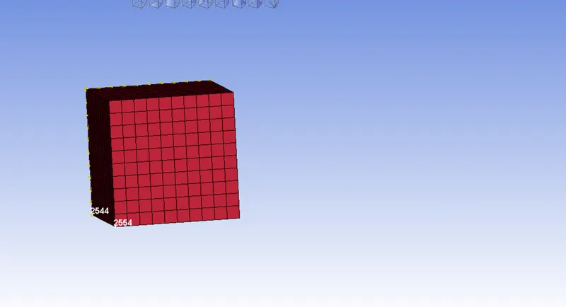
Set Nodes to constrain for a proper motion flow.
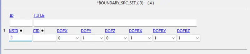
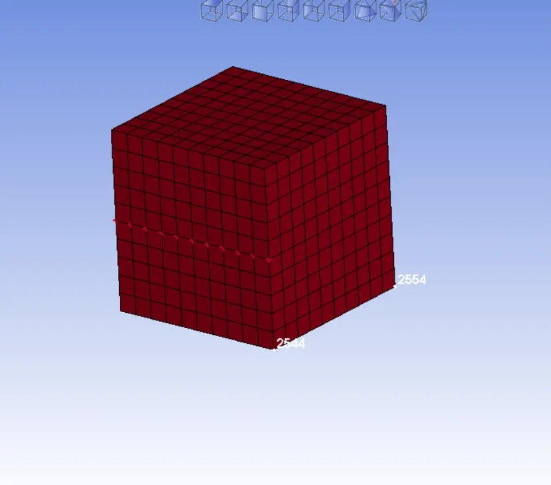
SPC_SET nodes 1:
For this condition, I have selected the mid nodes of the solid model, with Y translational is been constrained and all rotational nodes are been constrained.
Why we constrain Y in this because, the chosen nodes will tend to move in the forward direction, for that Y is been constrained.
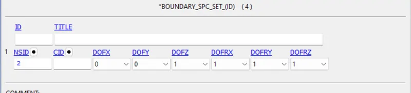
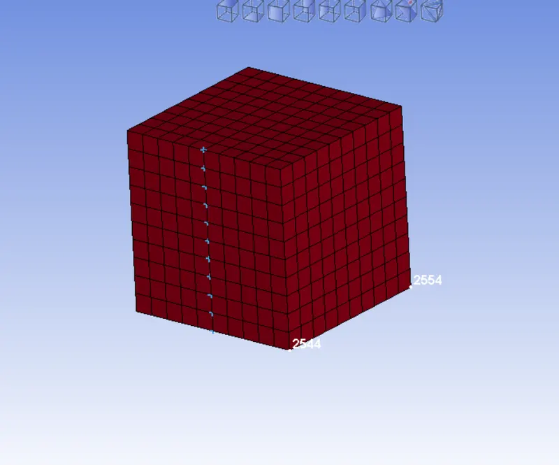
SPC Set Node 2:
For this condition, I have selected the mid nodes of the solid model in the Y axis, with Z translational is been constrained and all rotational nodes are been constrained.
SPC Set Nodes 3:
For this condition, I have selected the mid nodes of the solid model in the Y axis, with Z translational is been constrained and all rotational nodes are been constrained.
To perform a simulation in the Solid Box, anyone node has to be constrained in all directions.
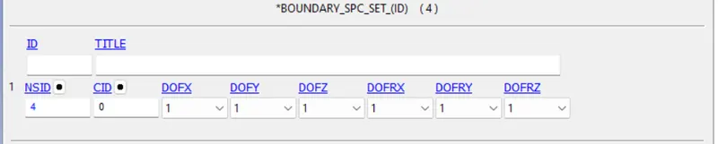
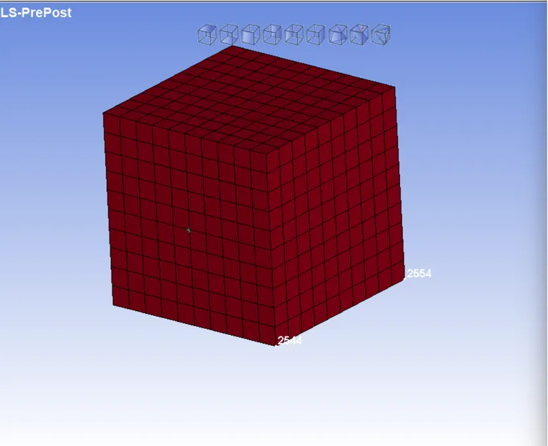
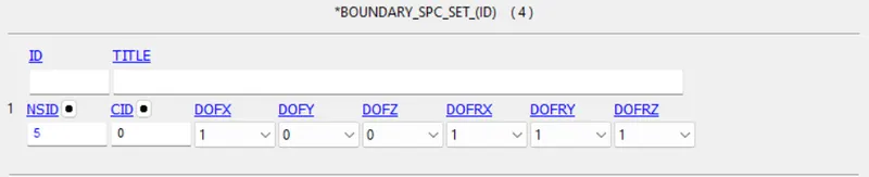
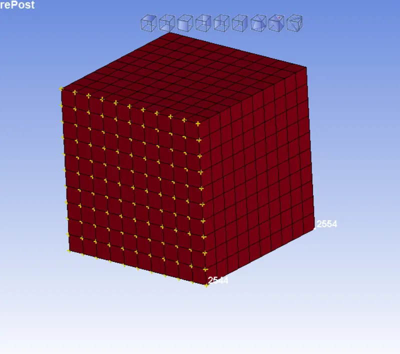
SPC Set Nodes 4:
Since the transitional is going to occur in the X-direction, so we have to choose all the nodes in that face, and to arrest the motion in the X direction, we are constrained in the X-Transition.
Prescribed Motion Set:
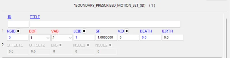
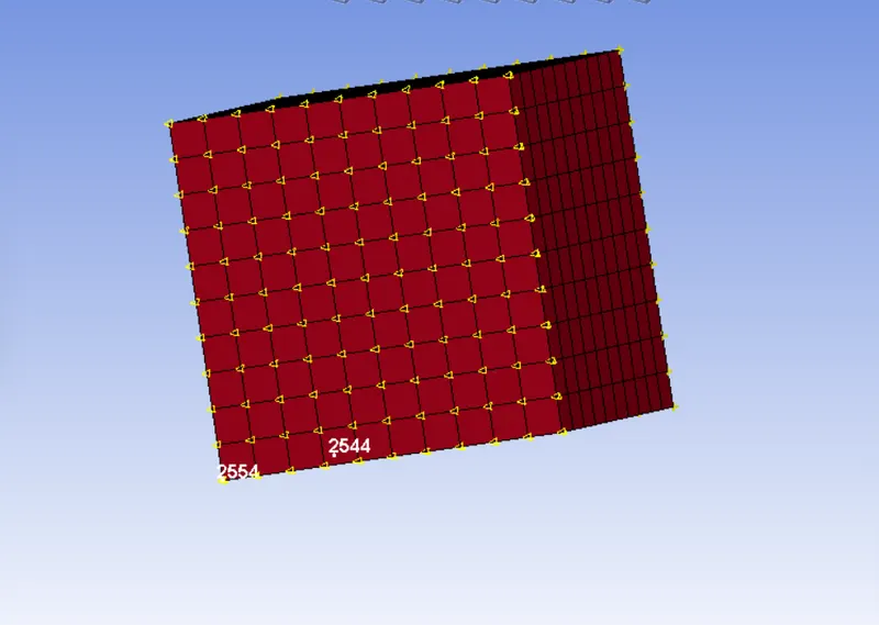
It is assigned, for the motion of the nodes needs to take place.
here the DOF is set to 1 which is in the X direction, VAD is set to 2 for the Displacement of the nodes, LCID is assigned, and Shear Factor is also assigned.
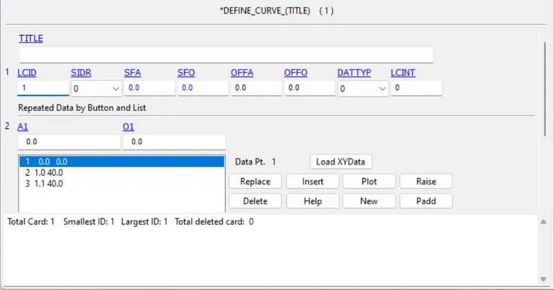
LCID:
Absicca and Ordinate are assigned and shown below.
O2 is set to 40 that is because of stretch ratio is set to 5.
The total change that needs to occur is 50 so that 40 is taken.
Material:
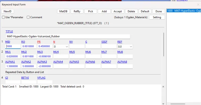
As the Stretch Ratio is set to 5, in meantime we have to consider the 077_O_Odgen_Rubber.
Since the Higher Stretch ratio, the material is said to be Hyperelastic, and metal has a 0.8 to 2 Stretch ratio.
Section Card:
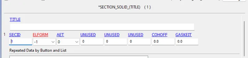
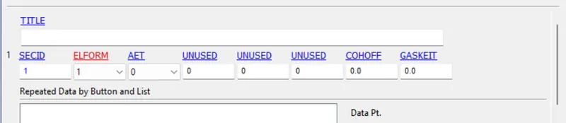
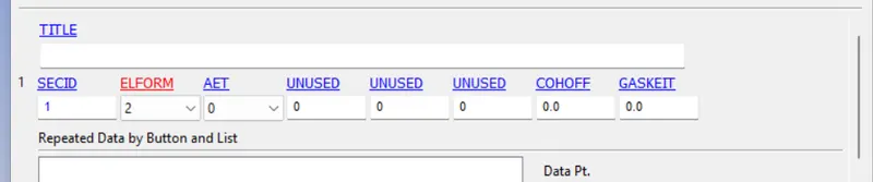
4 different element form are been considered for this simulation.
ELFORM -1:
ELFORM -2:

ELFORM 1:
ELFORM 2:
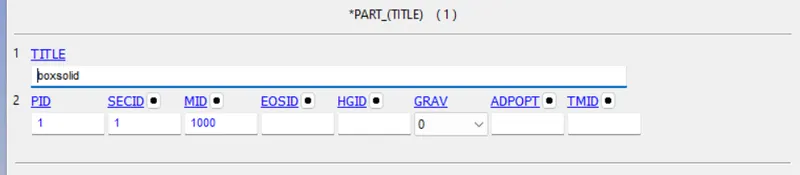
PART:
Part is been assigned with material and section.
IMPLICIT Method:
Since the model is set for Implicit analysis, we have to define some certain keywords to run this model.
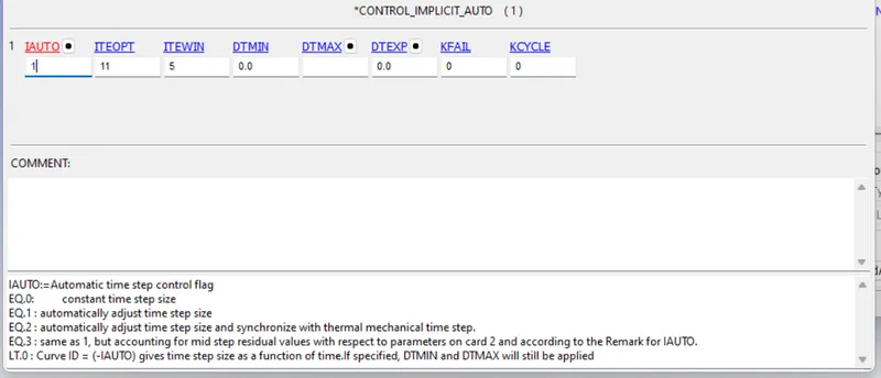
Contact_Implicit_Auto:
This is considered for Timestep, here 1 is considered, and the rest of the things are set to default.
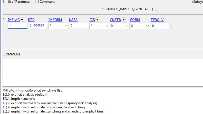
Contact_General:
For IMFLAG is set to 1, Implicit analysis.
Time step DT0 is set to 0.1.
Contact Solution:
This keyword is set to default
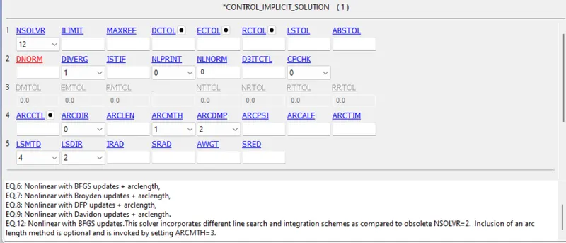
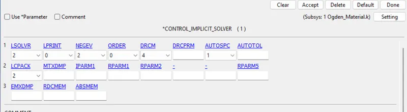
Contact Solver:
This is also set to default
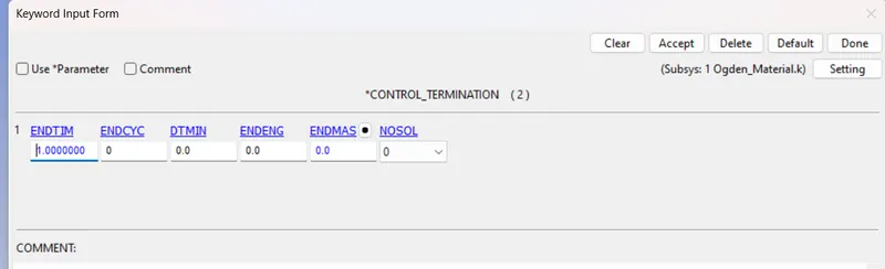
Control Termination:
Here the termination time is set to 1.
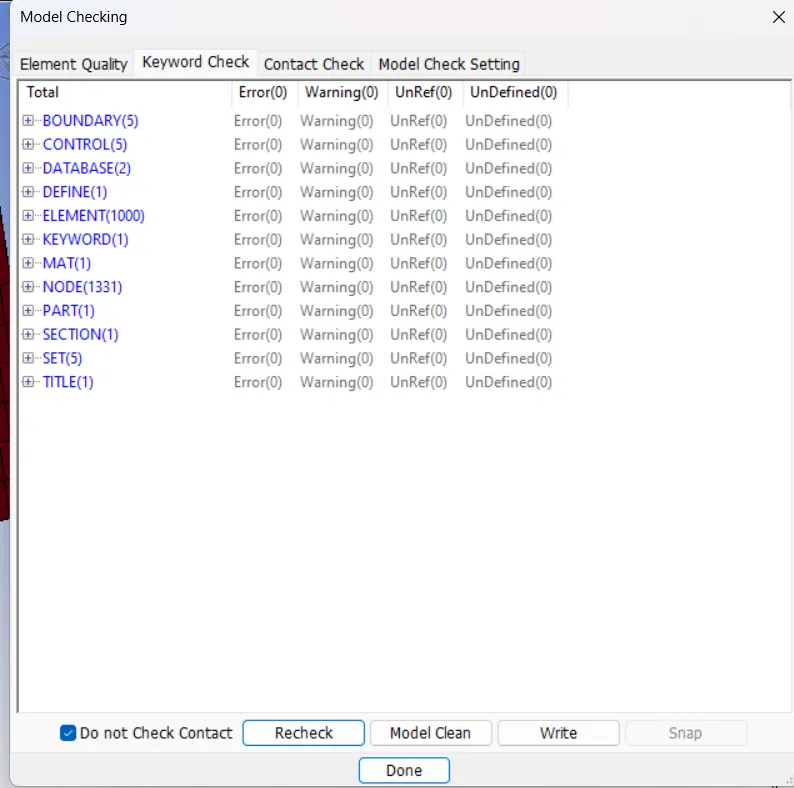
Check for the model:
By using the Model checkup option we can check whether any changes as to be done to the model.
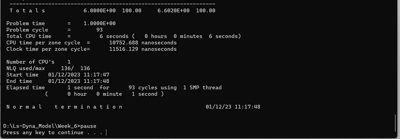
Run the LS-Run:
Post-Processor:
Animation File:
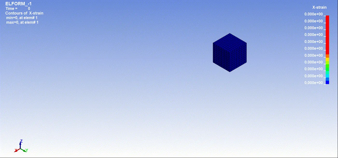
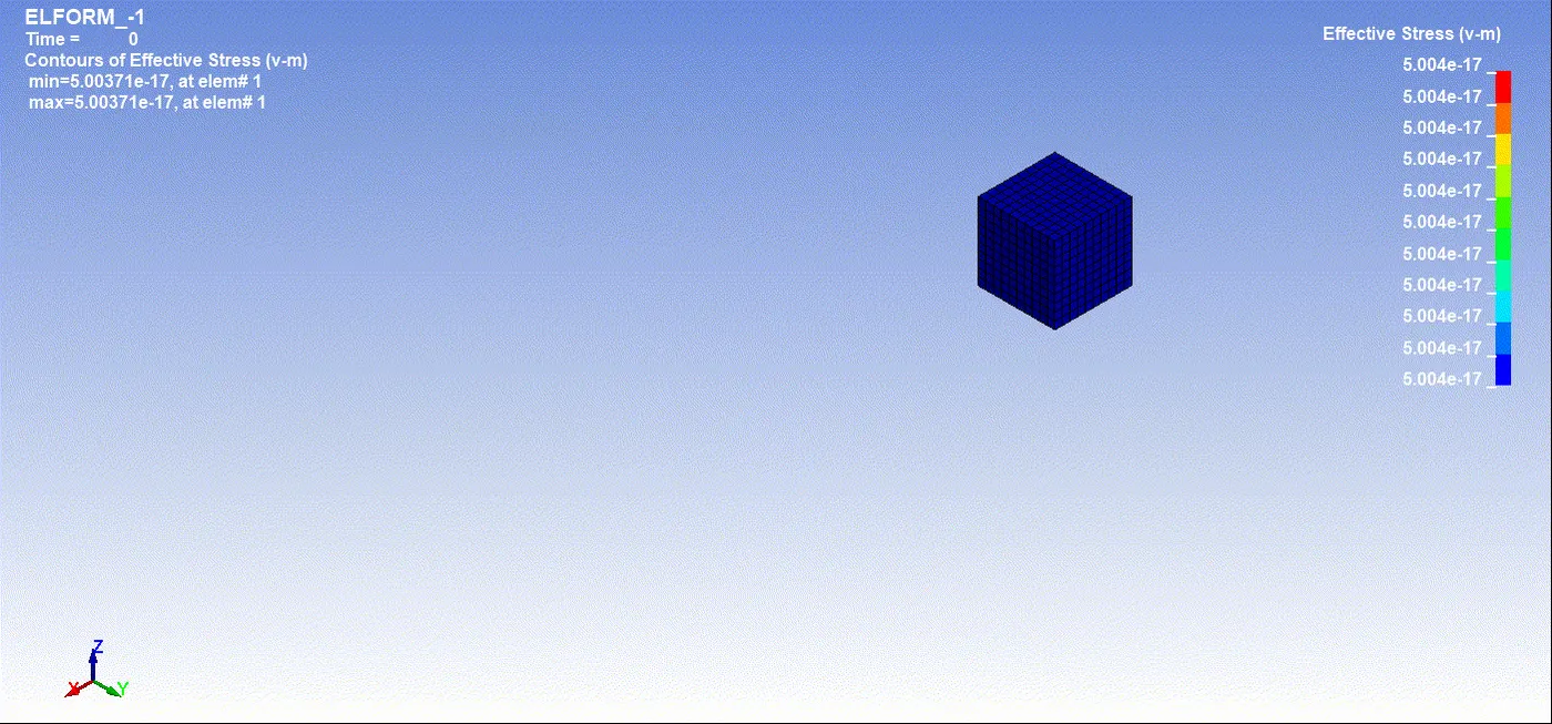
ELFORM -1:
For X-Strain:
For Von-mises stress:
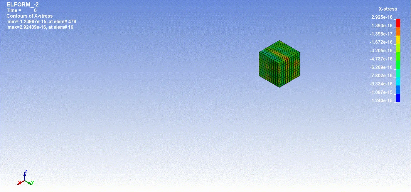
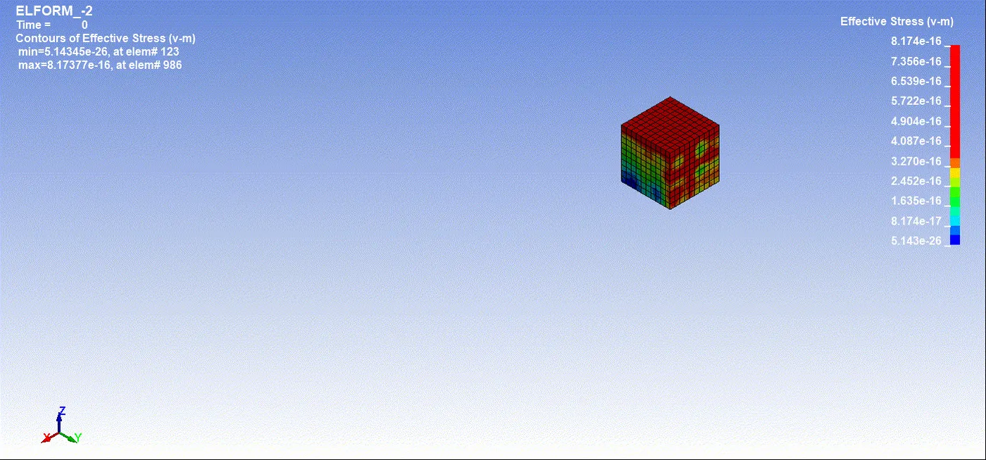
ELFORM -2:
For X-Strain:
For Von-Mises Stress:
ELFORM 1:
For X-Strain:
For Von-Mises Stress:
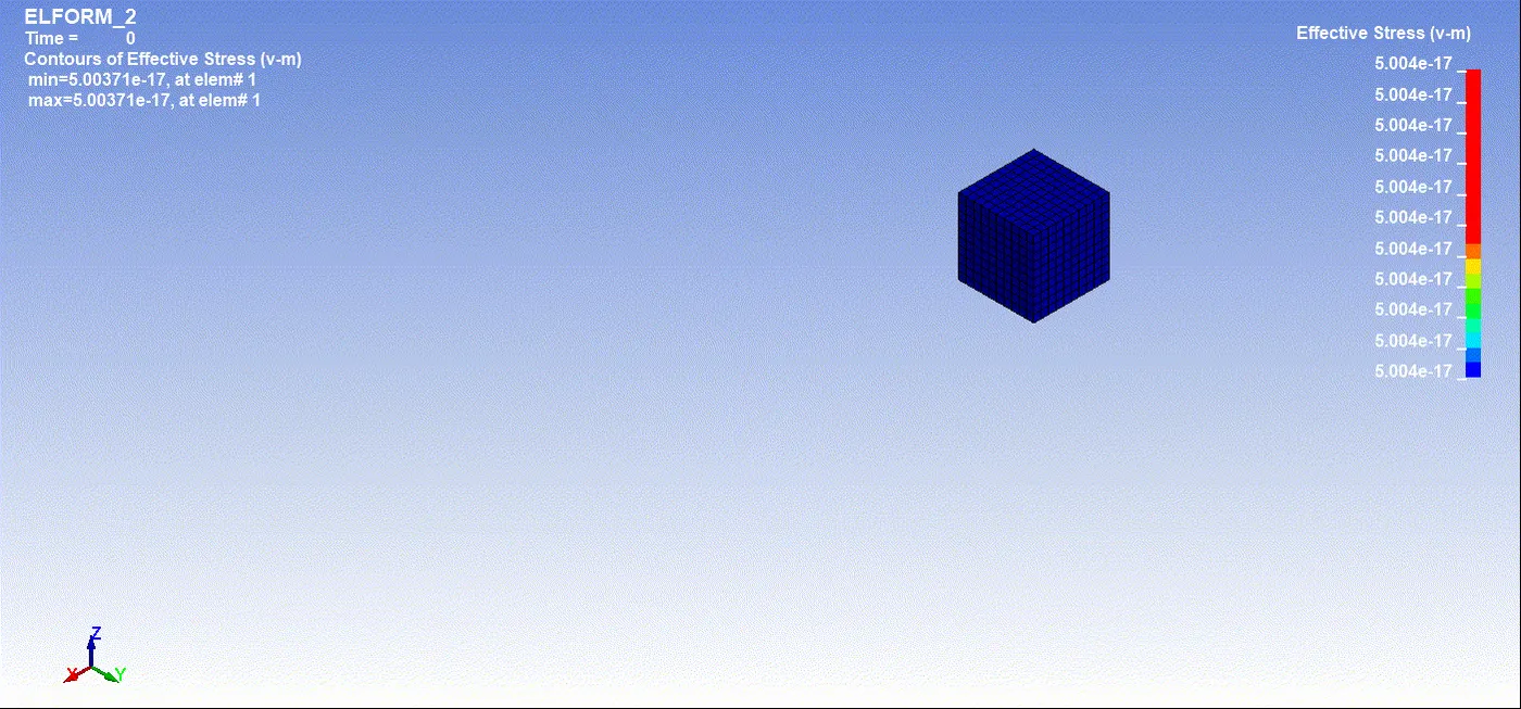
ELFORM 2:
For X-Strain:
For Von-Mises Stress:
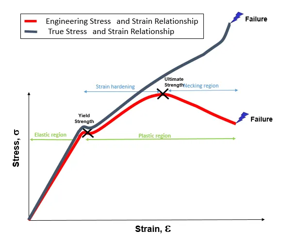
Engineering Stress, Strain VS True Stress and Strain:
Stress-strain curve for the material is plotted by elongating the sample and recording the stress variation with strain until the sample fractures. The strain is set to the horizontal axis and stress is set to the vertical axis. It is often assumed that the cross-section area of the material does not change during the whole deformation process. This is not true since the actual area will decrease while deforming due to elastic and plastic deformation. The curve based on the original cross-section and gauge length is called the engineering stress-strain curve, while the curve based on the instantaneous cross-section area and length is called the true stress-strain curve.
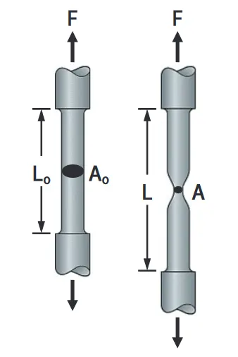
Engineering stress is the applied load divided by the original cross-sectional area of a material. Also known as nominal stress.
True stress is the applied load divided by the actual cross-sectional area (the changing area with respect to time) of the specimen at that load.
Engineering strain is the amount that a material deforms per unit length in a tensile test. Also known as nominal strain.
True strain equals the natural log of the quotient of the current length over the original length.
Stress, Strain, and Stretch Ratio:
The stretch ratio is defined as the ratio between the final length and the initial length of a component.
This is equal to (1 + Engineering Strain).
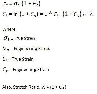
As we know that the values of stress and strain we get in LS -Dyna will be in the form of True Stress and True Strain. So we have to convert it into Engineering Stress and Engineering Strain to get the Stretch Ratio.
These conversions can be done by the equations given below:
Calculation of Nominal Stress & Stretch Ratio:
Now we will see the calculation of the Nominal Stress and Stretch Ratio for all cases.
- After getting the values of True strain and True stress from the plots, we can use the XY data and export it as a “CSV” file, and open it in EXCEL.
- Here all the data of True Stress and rue Strain are collected for all cases using element results from the middle of the cube, which is Element 948.
- So all the results will be regarding Element ID: 948
- Here Stress results for Element 948 will be from X-Stress
- Strain results for Element 948 will be from Lower Imp X-Strain.
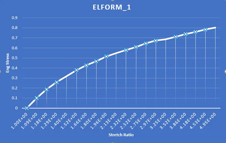
ELFORM 1:
| ELFORM_1_H948 | ||||
| True_strain | True_stress | Stretch Ratio | Eng Stress | Eng Strain |
| 0.00E+00 | 0.00E+00 | 1.00E+00 | 0.00E+00 | 0.00E+00 |
| 8.41E-02 | 1.11E-01 | 1.09E+00 | 1.02E-01 | 8.77E-02 |
| 1.68E-01 | 2.22E-01 | 1.18E+00 | 1.88E-01 | 1.83E-01 |
| 2.52E-01 | 3.33E-01 | 1.29E+00 | 2.59E-01 | 2.87E-01 |
| 3.36E-01 | 4.45E-01 | 1.40E+00 | 3.18E-01 | 3.99E-01 |
| 4.20E-01 | 5.77E-01 | 1.52E+00 | 3.79E-01 | 5.22E-01 |
| 5.05E-01 | 7.09E-01 | 1.66E+00 | 4.28E-01 | 6.57E-01 |
| 5.89E-01 | 8.43E-01 | 1.80E+00 | 4.68E-01 | 8.02E-01 |
| 6.73E-01 | 1.01E+00 | 1.96E+00 | 5.15E-01 | 9.60E-01 |
| 7.57E-01 | 1.17E+00 | 2.13E+00 | 5.49E-01 | 1.13E+00 |
| 8.41E-01 | 1.34E+00 | 2.32E+00 | 5.78E-01 | 1.32E+00 |
| 9.25E-01 | 1.54E+00 | 2.52E+00 | 6.11E-01 | 1.52E+00 |
| 1.01E+00 | 1.77E+00 | 2.75E+00 | 6.45E-01 | 1.75E+00 |
| 1.09E+00 | 2.00E+00 | 2.97E+00 | 6.73E-01 | 1.97E+00 |
| 1.18E+00 | 2.23E+00 | 3.25E+00 | 6.85E-01 | 2.25E+00 |
| 1.26E+00 | 2.51E+00 | 3.52E+00 | 7.12E-01 | 2.52E+00 |
| 1.35E+00 | 2.85E+00 | 3.86E+00 | 7.39E-01 | 2.86E+00 |
| 1.43E+00 | 3.18E+00 | 4.18E+00 | 7.61E-01 | 3.18E+00 |
| 1.51E+00 | 3.55E+00 | 4.53E+00 | 7.84E-01 | 3.53E+00 |
| 1.60E+00 | 3.97E+00 | 4.95E+00 | 8.02E-01 | 3.95E+00 |
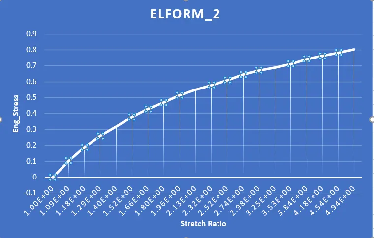
ELFORM 2:
| ELForm_2_H948 | ||||
| True-strain | True-Stress | Stretch Ratio | Eng Stress | Eng Strain |
| 0.00E+00 | -2.23E-16 | 1.00E+00 | -2.23E-16 | 0.00E+00 |
| 8.41E-02 | 1.11E-01 | 1.09E+00 | 1.02E-01 | 8.77E-02 |
| 1.68E-01 | 2.22E-01 | 1.18E+00 | 1.88E-01 | 1.83E-01 |
| 2.52E-01 | 3.33E-01 | 1.29E+00 | 2.59E-01 | 2.87E-01 |
| 3.36E-01 | 4.45E-01 | 1.40E+00 | 3.18E-01 | 4.00E-01 |
| 4.20E-01 | 5.77E-01 | 1.52E+00 | 3.79E-01 | 5.23E-01 |
| 5.05E-01 | 7.09E-01 | 1.66E+00 | 4.28E-01 | 6.56E-01 |
| 5.89E-01 | 8.43E-01 | 1.80E+00 | 4.68E-01 | 8.02E-01 |
| 6.73E-01 | 1.01E+00 | 1.96E+00 | 5.15E-01 | 9.60E-01 |
| 7.57E-01 | 1.17E+00 | 2.13E+00 | 5.51E-01 | 1.13E+00 |
| 8.41E-01 | 1.34E+00 | 2.32E+00 | 5.78E-01 | 1.32E+00 |
| 9.25E-01 | 1.54E+00 | 2.52E+00 | 6.10E-01 | 1.52E+00 |
| 1.01E+00 | 1.77E+00 | 2.74E+00 | 6.45E-01 | 1.74E+00 |
| 1.09E+00 | 2.00E+00 | 2.98E+00 | 6.71E-01 | 1.98E+00 |
| 1.18E+00 | 2.23E+00 | 3.25E+00 | 6.88E-01 | 2.25E+00 |
| 1.26E+00 | 2.51E+00 | 3.53E+00 | 7.11E-01 | 2.53E+00 |
| 1.35E+00 | 2.85E+00 | 3.84E+00 | 7.41E-01 | 2.84E+00 |
| 1.43E+00 | 3.18E+00 | 4.18E+00 | 7.62E-01 | 3.18E+00 |
| 1.51E+00 | 3.55E+00 | 4.54E+00 | 7.82E-01 | 3.54E+00 |
| 1.60E+00 | 3.97E+00 | 4.94E+00 | 8.04E-01 | 3.94E+00 |
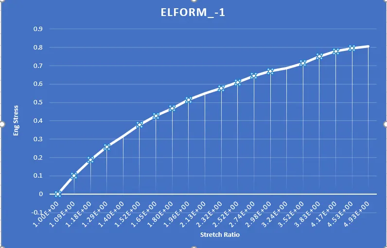
ELFORM -1:
| ELFORM_-1_H948 | ||||
| True_strain | True_stress | Stretch Ratio | Eng_Stress | Eng_Strain |
| 0.00E+00 | -2.23E-16 | 1.00E+00 | -2.23E-16 | 0.00E+00 |
| 8.40E-02 | 1.11E-01 | 1.09E+00 | 1.02E-01 | 8.76E-02 |
| 1.68E-01 | 2.22E-01 | 1.18E+00 | 1.87E-01 | 1.83E-01 |
| 2.52E-01 | 3.32E-01 | 1.29E+00 | 2.58E-01 | 2.86E-01 |
| 3.36E-01 | 4.44E-01 | 1.40E+00 | 3.17E-01 | 3.99E-01 |
| 4.20E-01 | 5.76E-01 | 1.52E+00 | 3.78E-01 | 5.22E-01 |
| 5.04E-01 | 7.08E-01 | 1.65E+00 | 4.28E-01 | 6.55E-01 |
| 5.88E-01 | 8.41E-01 | 1.80E+00 | 4.67E-01 | 8.00E-01 |
| 6.72E-01 | 1.01E+00 | 1.96E+00 | 5.14E-01 | 9.57E-01 |
| 7.56E-01 | 1.17E+00 | 2.13E+00 | 5.50E-01 | 1.13E+00 |
| 8.40E-01 | 1.34E+00 | 2.32E+00 | 5.77E-01 | 1.32E+00 |
| 9.23E-01 | 1.53E+00 | 2.52E+00 | 6.09E-01 | 1.52E+00 |
| 1.01E+00 | 1.77E+00 | 2.74E+00 | 6.45E-01 | 1.74E+00 |
| 1.09E+00 | 2.00E+00 | 2.98E+00 | 6.71E-01 | 1.98E+00 |
| 1.18E+00 | 2.23E+00 | 3.24E+00 | 6.88E-01 | 2.24E+00 |
| 1.26E+00 | 2.51E+00 | 3.52E+00 | 7.14E-01 | 2.52E+00 |
| 1.34E+00 | 2.88E+00 | 3.83E+00 | 7.51E-01 | 2.83E+00 |
| 1.43E+00 | 3.24E+00 | 4.17E+00 | 7.78E-01 | 3.17E+00 |
| 1.51E+00 | 3.61E+00 | 4.53E+00 | 7.96E-01 | 3.53E+00 |
| 1.60E+00 | 3.97E+00 | 4.93E+00 | 8.06E-01 | 3.93E+00 |
ELFORM -2:
| ELFORM_-2_H948 | ||||
| True-strain | True-stress | Stretch Ratio | Eng Stress | Eng Strain |
| 0.00E+00 | -3.92E-16 | 1.00E+00 | -3.92E-16 | 0.00E+00 |
| 8.41E-02 | 1.11E-01 | 1.09E+00 | 1.02E-01 | 8.77E-02 |
| 1.68E-01 | 2.22E-01 | 1.18E+00 | 1.88E-01 | 1.83E-01 |
| 2.52E-01 | 3.33E-01 | 1.29E+00 | 2.59E-01 | 2.87E-01 |
| 3.36E-01 | 4.45E-01 | 1.40E+00 | 3.18E-01 | 4.00E-01 |
| 4.20E-01 | 5.77E-01 | 1.52E+00 | 3.79E-01 | 5.23E-01 |
| 5.05E-01 | 7.09E-01 | 1.66E+00 | 4.28E-01 | 6.56E-01 |
| 5.89E-01 | 8.43E-01 | 1.80E+00 | 4.68E-01 | 8.02E-01 |
| 6.73E-01 | 1.01E+00 | 1.96E+00 | 5.15E-01 | 9.60E-01 |
| 7.57E-01 | 1.17E+00 | 2.13E+00 | 5.51E-01 | 1.13E+00 |
| 8.41E-01 | 1.34E+00 | 2.32E+00 | 5.78E-01 | 1.32E+00 |
| 9.25E-01 | 1.54E+00 | 2.52E+00 | 6.10E-01 | 1.52E+00 |
| 1.01E+00 | 1.77E+00 | 2.74E+00 | 6.45E-01 | 1.74E+00 |
| 1.09E+00 | 2.00E+00 | 2.98E+00 | 6.71E-01 | 1.98E+00 |
| 1.18E+00 | 2.23E+00 | 3.25E+00 | 6.88E-01 | 2.25E+00 |
| 1.26E+00 | 2.51E+00 | 3.53E+00 | 7.11E-01 | 2.53E+00 |
| 1.35E+00 | 2.85E+00 | 3.84E+00 | 7.41E-01 | 2.84E+00 |
| 1.43E+00 | 3.18E+00 | 4.18E+00 | 7.62E-01 | 3.18E+00 |
| 1.51E+00 | 3.55E+00 | 4.54E+00 | 7.82E-01 | 3.54E+00 |
| 1.60E+00 | 3.97E+00 | 4.94E+00 | 8.04E-01 | 3.94E+00 |
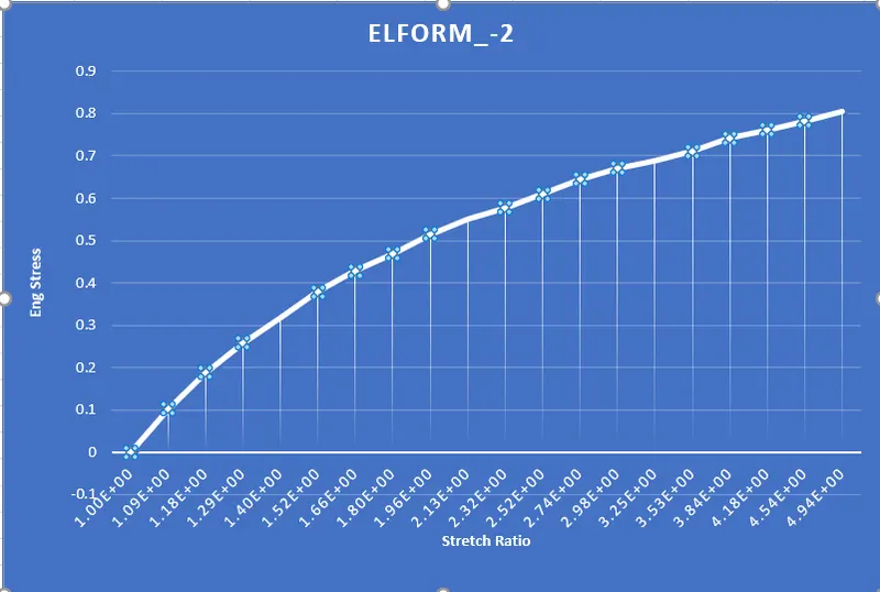
As Compared to all Element Forms Elform 1 has more closet value of 4.94 as a Stretch Ratio.
Conclusion:
- Since this is the uniaxial tensile test, we are getting similar results for different element formulations.
- Also, the deformation we have given to the cube was not so large for this type of hyperelastic material, so the difference cannot be observed.
- For different boundary conditions and different loading conditions, we can get different results with changes in element formulation type in a more efficient manner and clearly visible.
- Since the element formulation (1) is constant stress solid element, which default, an element is invoked, which is good to propose the strain energy function.
- Element formulation (2) is a selective reduced integrated solid element, which gives constant pressure throughout the element to avoid pressure locking, but the type (1) is more accurate than type (2) for implicit problems.
- Element formulation types (-1) and (-2) are fully integrated elements intended for elements with poor aspect ratios. Among which type (-1) is more efficient and type (-2) is a more accurate formulation.
- Since Element formulation (-1) has some side effects related to some particular deformation modes, we can conclude that Element formulation (-2) is more accurate and mostly preferred for the solid elements in Implicit problems.