Week-6 Calculate the Stretch Ratio by comparing the ELFORM (-2,-1,1,2) with Ogden_Material Model.
AIM
Tensile test to be done for the cube with implicit method.
OBJECTIVE
- Creating box with 10mmX10mmX10mmX10mm dimension with 10 elements in each face.
- Tensile test with implicit method.
- Compare different ELFORM 1, -1,2, -2.
- Compare stretch ratio.
THEORY
Implicit method: In this method next step is found from current and later state of equation. This method is more accurate and time consuming and more computer storage required. Dynamic problems like vibration etc. are done with this method.
PROCEDURE
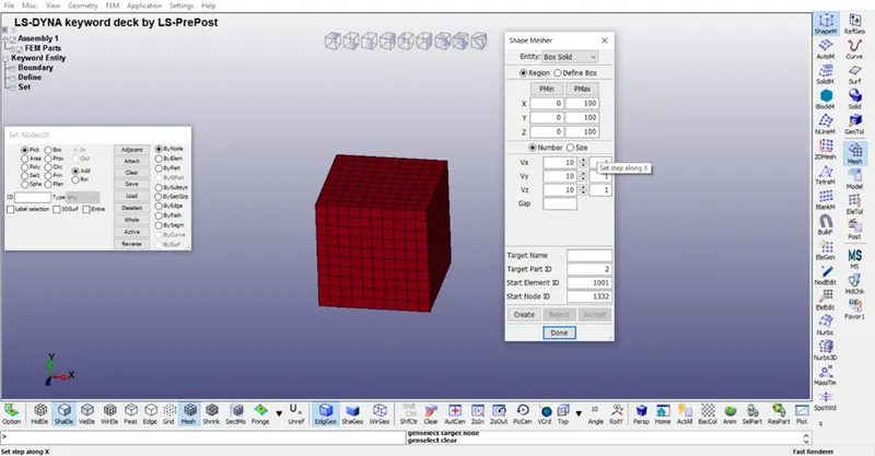
- Cube creation: In this section box is created in Ls Dyna with dimension of 10mmX10mmX10mmX10mm and 10 elements in each face.
MESH < SHAPE MESHER
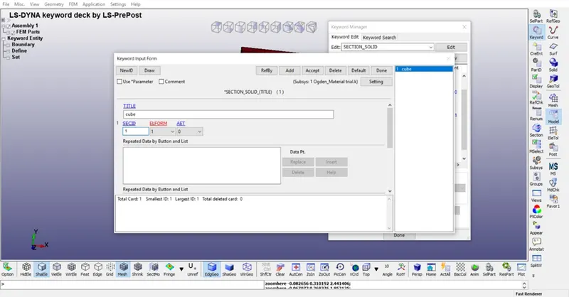
- Section: In this Part solid section is created with different ELFORM 1,-1,2,-2.
MODEL < KEYWORD < SECTION < SOLID
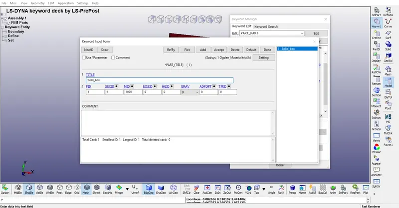
- Part: In this section and material is connected.
MODEL < KEYWORD < PART
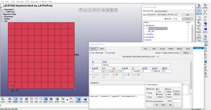
- Boundary conditions: In this part one side nodes are fixed and another side of nodes are provided with motion.
MODEL < KEYWORD < BOUNDARY < SPC

MODEL < KEYWORD < PRESCRIBED MOTION SET < SOLID
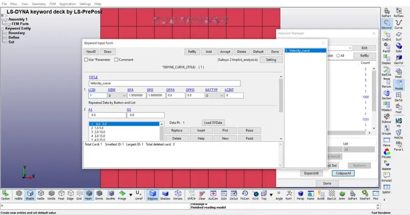
- Curve: For defining motion velocity curve is defined.
MODEL < KEYWORD < DEFINE < CURVE
- Control: This keyword is mainly used for the alter the default analysis criteria.
IMPLICIT GENERAL: This keyword is used for the activating Implicit analysis.
MODEL < KEYWORD < CONTROL < IMPLICIT GENERAL
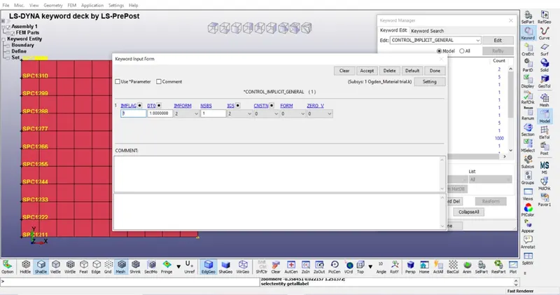
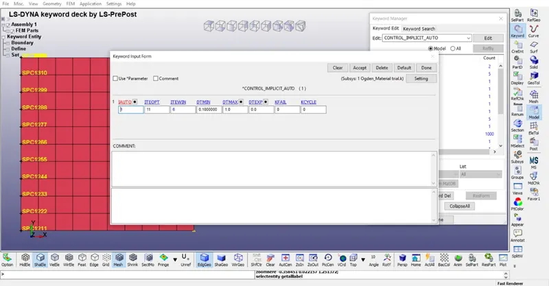
IMPLITIT AUTO This keyword is introduced for automatic time step control during implicit analysis.
MODEL < KEYWORD < CONTROL < IMPLICIT AUTO
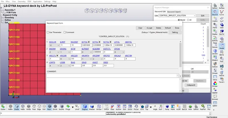
IMPLICIT SOLUTION card is applicable to alter implicit calculation and specify weather analysis is Linear and Non-Linear.
MODEL < KEYWORD < CONTROL < IMPLICIT SOLUTION
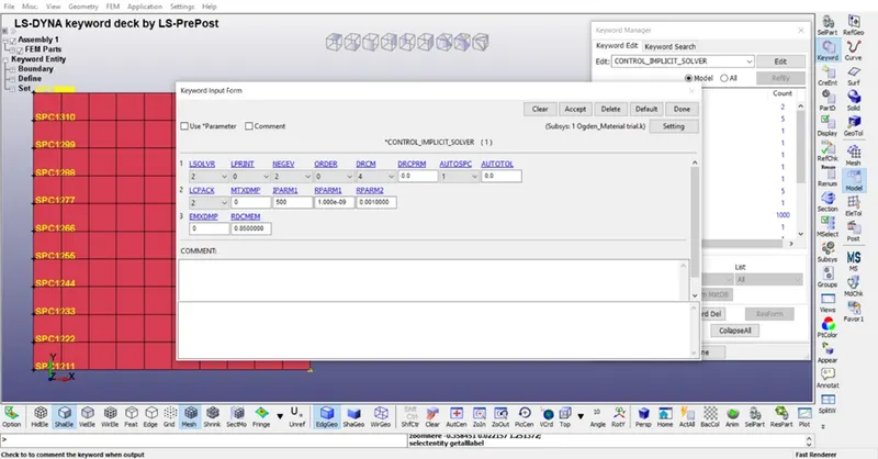
IMPLICIT SOLVER is used for alter implicit calculation specially for Linear solver it perform CPU-intensive stiffness matrix inversion.
MODEL < KEYWORD < CONTROL < IMPLICIT SOLVER
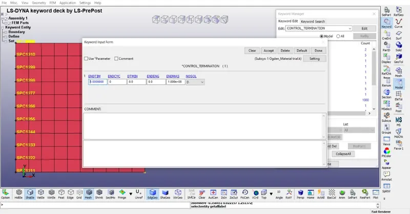
Termination time is also provided for stopping the simulation.
MODEL < KEYWORD < CONTROL < TERMINATION
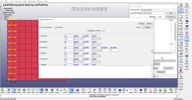
- DATABASE In this section different outputs are defined
ASCII In this NODFOR,NODOUT is defined.
MODEL < KEYWORD < DATABASE < ASCII
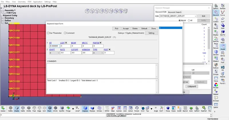
Binary D3plot is defined.
MODEL < KEYWORD < DATABASE < D3PLOT
EXTEND BINARY is defined for the control the binary output.
MODEL < KEYWORD < DATABASE < EXTEND BINARY
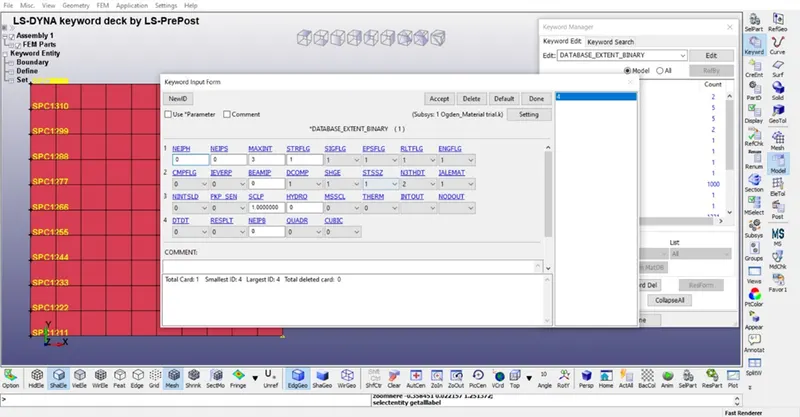
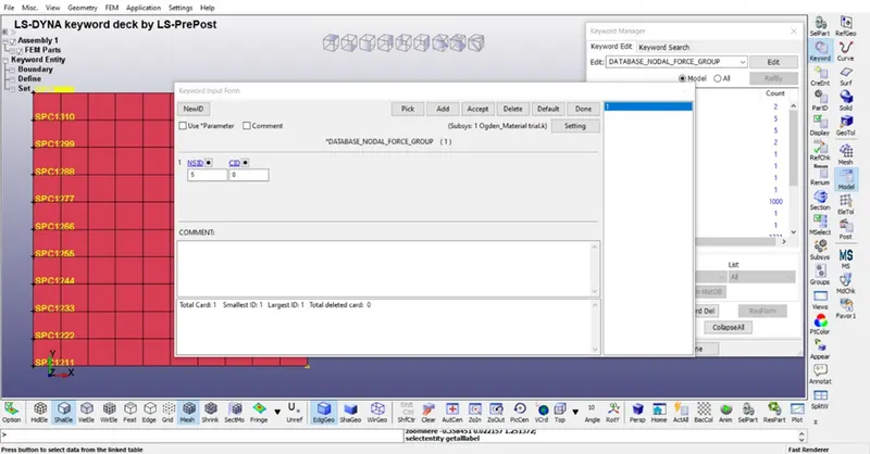
NODAL FORCE GROUP is defined for output into ASCII file NODFOR
MODEL < KEYWORD < DATABASE < NODAL FORCE GROUP
RESULTS
From the simulation results are listed below.
|
ELFORM |
Maximum Stress (g/mm ms2) |
Stretch Ratio |
|
1 |
0.6525131 |
3.99 |
|
-1 |
0.649 |
4.0365785 |
|
2 |
0.649 |
4.0365785 |
|
-2 |
0.649 |
4.0315637 |
CONCLUSION
In this implicit analysis we get to know that maximum stress and strain ratio is shown above.