Week-6 Calculate the Stretch Ratio by comparing the ELFORM (-2,-1,1,2) with Ogden_Material Model.
Calculate the Stretch Ratio by comparing the ELFORM (-2,-1,1,2) with Ogden_Material Model.
AIM: To perform the simulation using ELFORM = 1, 2, -1, -2 and calculate the stretch ratio.
SOFTWARE: LS-Dyna
OBJECTIVE:
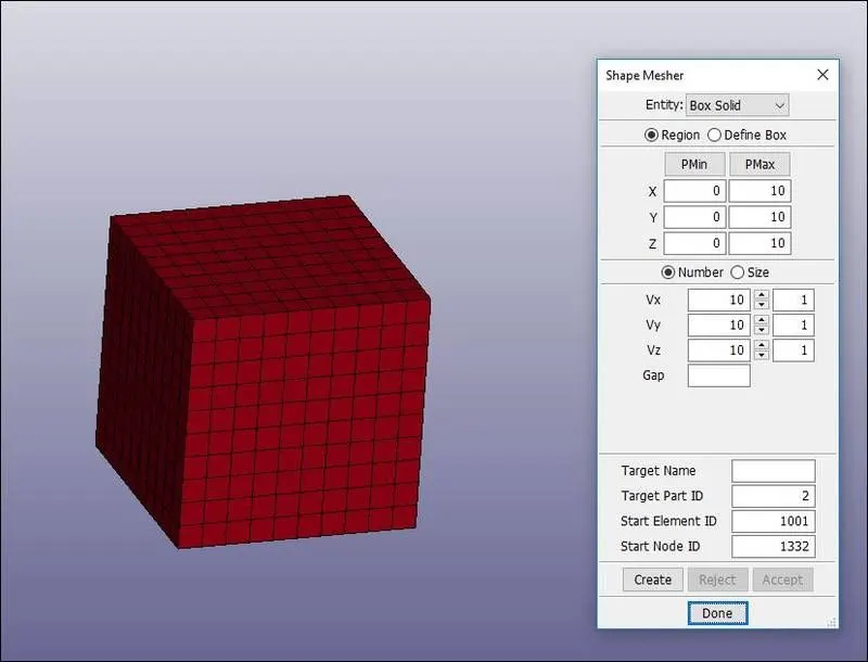
1) To Create a block of 10mmx10mmx10mm dimension with 10 elements for each direction and use the material card attached (Ogden_Material.k).
2) Use appropriate boundary conditions to simulate uniaxial tensile behavior for the model.
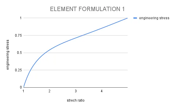
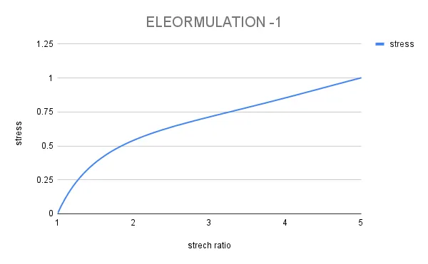
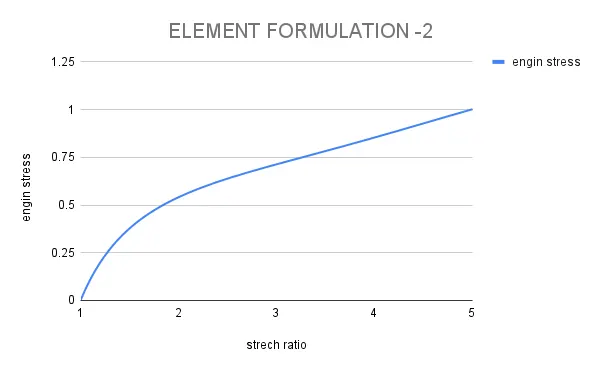
3) Compare the results of the simulation with ELFORM = 1, 2, -1, -2 by plotting Engineering Stress vs Stretch Ratio up to stretch ratio 5.
4) To use a proper solver (Implicit/Explicit).
INTRODUCTION:
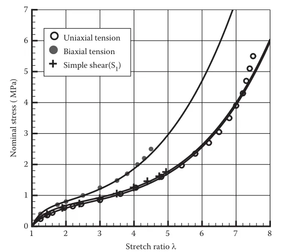
An Ogden model is a hyperelastic material model that can be used for predicting the nonlinear stress-strain behavior of materials such as rubber or polymer. Ogden's model has introduced Ogden in 1972. The Ogden model has been frequently used for the analysis of rubber components like O-ring and seal. Even though the Ogden model is a hyperelastic material model, its strain energy density function is expressed by the principal stretch ratio.
Engineering strain and True strain:
Engineering strain is expressed as the ratio of total deformation to the initial dimension of the material body in which the forces are being applied.
The engineering normal strain or extensional strain or nominal strain e of a material line element or fiber axially loaded is expressed as the change in length ΔL per unit of the original length L of the line element or fibers.
The normal strain is positive if the material fibers are stretched and negative if they are compressed.
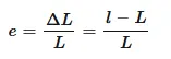
where e is the engineering normal strain, L is the original length of the body and l is the final length of the body.
Measures of strain are often expressed in terms of parts per million or microstrains.
The logarithmic strain is the true strain. Considering an incremental strain,

The logarithmic strain is obtained by integrating this incremental strain,
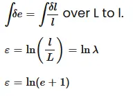
where e is the engineering strain and εε is the true strain.
The logarithmic strain provides the correct measure of the final strain when deformation takes place in a series of increments, taking into account the influence of the strain path
Stretch ratio:
Stretch ratio is a measure, used for highly extensible materials such as rubber, of normal component of strain subjected to tension, and is defined as the ratio of deformed length to the original length of the material body.
The stretch ratio is used in the analysis of materials that exhibit large deformations, such as elastomers, which can sustain stretch ratios of 3 or 4 before they fail.
On the other hand, traditional engineering materials, such as concrete or steel, fail at much lower stretch ratios.
Stretch ratio is defined as the ratio between the final length l and the initial length L of the material line.
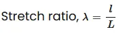
The relation between stretch ratio and engineering strain is given by
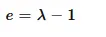
This equation implies that the normal strain is zero, so that there is no deformation when the stretch is equal to unity.
PROCEDURE:
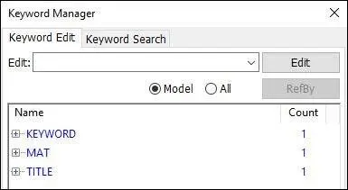
1) The given LS-Dyna keyword file is opened in LS-PrePost using the option File->Open->LS-Dyna Keyword File. The imported keyword file consists of only the Ogden material card as shown in the image given below.
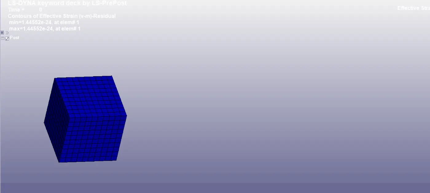
2) The FE model of a solid block of 10mmx10mmx10mm dimension with 10 elements for each direction is created using the Shape Mesher under the mesh tab as shown in the image given below.
Section Creation:
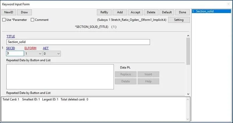
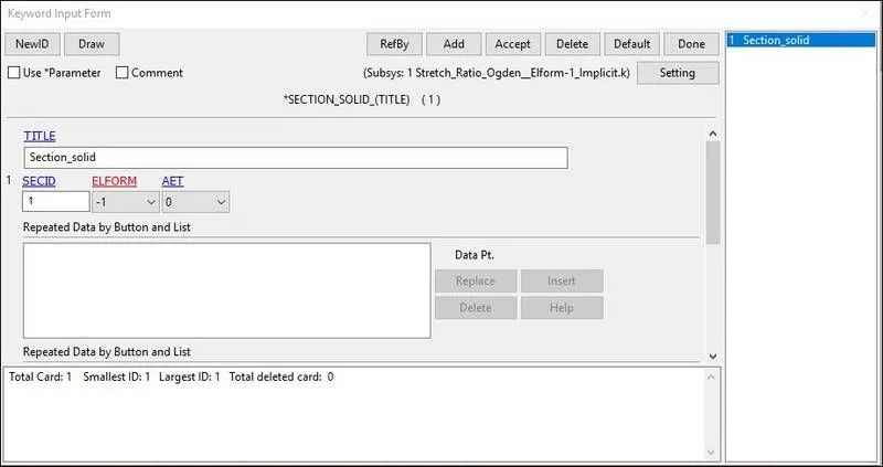
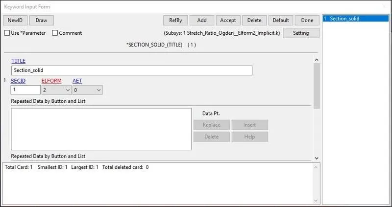
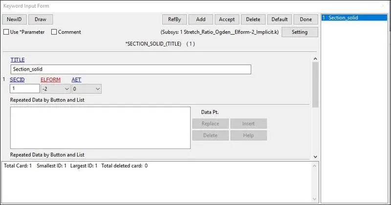
3) The section properties of the FE model created is assigned as a solid element with different ELFORM such as,
Case (1). ELFORM = 1, constant stress solid element.
Case (2). ELFORM = -1, Fully integrated S/R solid intended for elements with poor aspect ratio, efficient formulation.
Case (3). ELFORM = 2, Fully integrated S/R solid
Case (4). ELFORM = -2, Fully integrated S/R solid intended for elements with poor aspect ratio, accurate formulation.
Material:
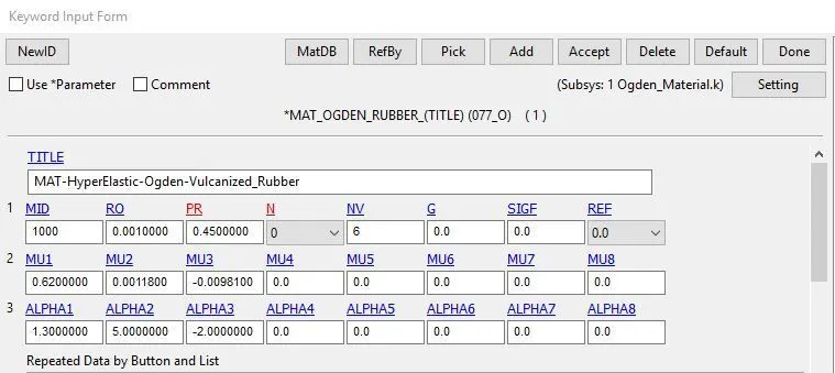
4) The material card given in the below image is OGDEN HYPERELASTIC MATERIAL with N3 order of polynomial, the unit system followed is gm-mm-ms and it is assigned to the solid block part.
Assigning Material and Section to Part:
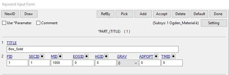
5) The material and section properties are assigned to the solid part as shown in the image given below.
Boundary Conditions:
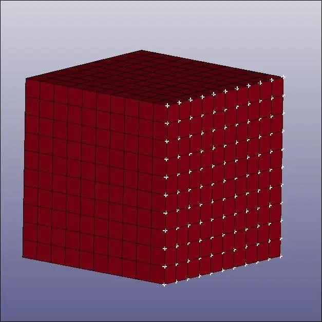
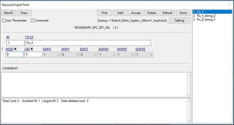
6) To perform the uniaxial tensile test on the specimen, the nodes of one of the faces are fixed along the X-axis.
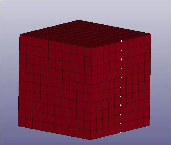
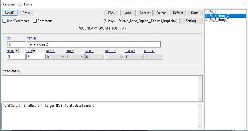
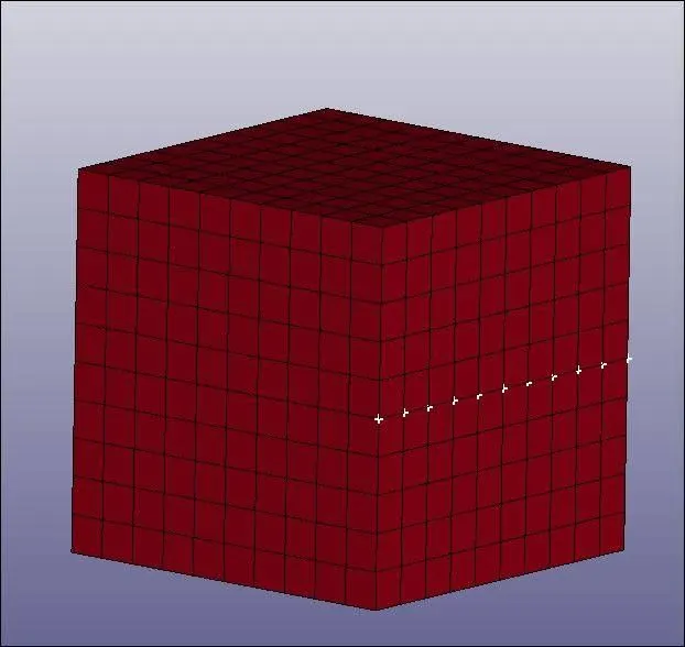
7) Then we fix the vertical middle nodes along Z- direction fixed in Y-direction.
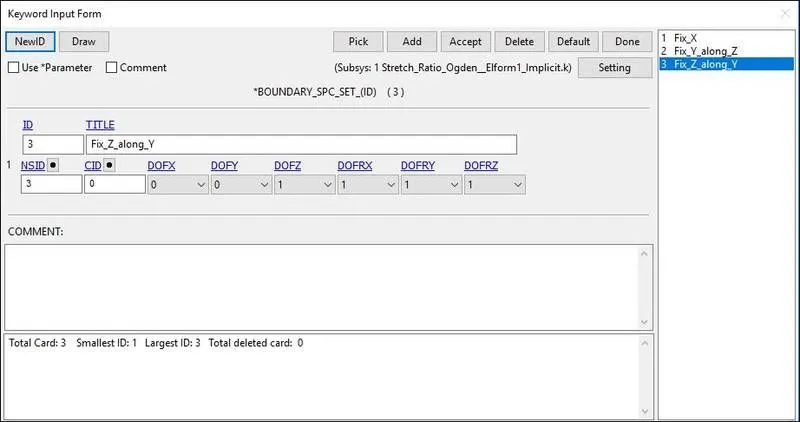
8) Then we fix the horizontal Middle nodes along Y-direction fixed in Z-direction.
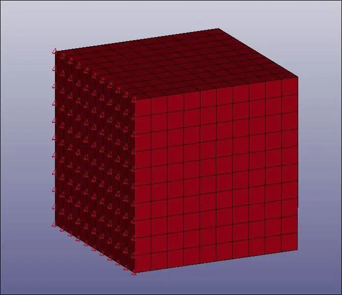
9) The Nodes in the moving face are selected for applying load.
10) The minimum load to be applied on the moving surface to attain a stretch ratio of 5, is calculated by using the following relation,
True strain = ln (1+Engg.strain)
Stretch Ratio = 1+Engg.strain
5 = 1+ ( delta L / L )
delta L = 40 mm
Hence, the minimum value of 40mm is taken to define the load curve.
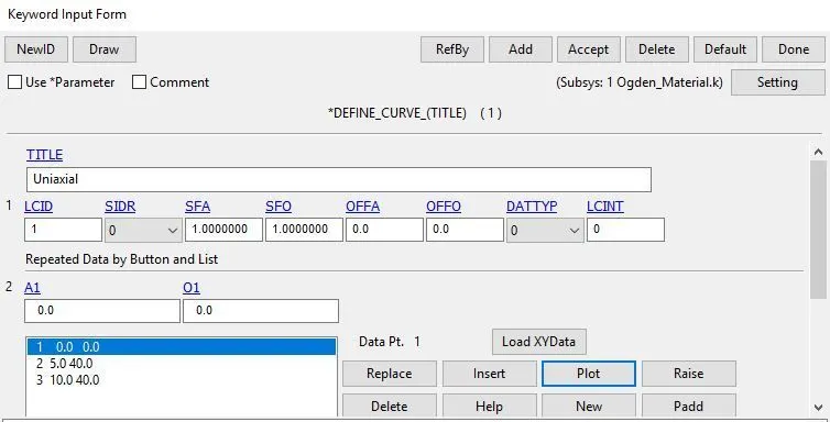
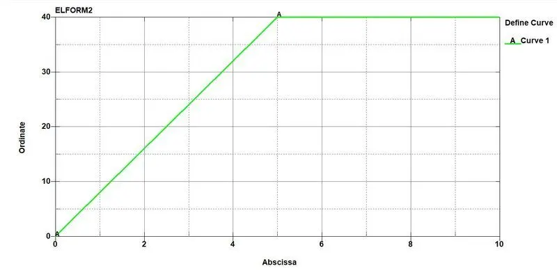
11) The node-set and load curve ID's are assigned to the prescribed motion set so the selected nodes move along the X-direction.
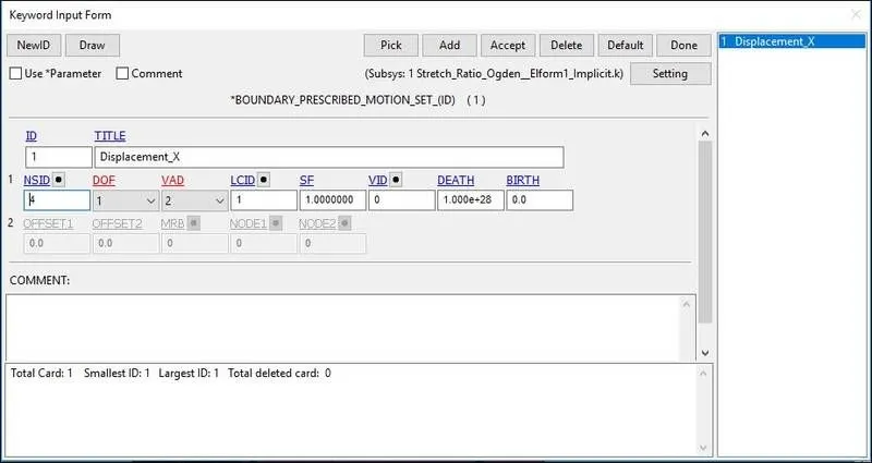
12) Control cards:
- CONTROL_TERMINATION( for simulation time)
- CONTROL_IMPLICIT_GENERAL(for enabling the implicit analysis)
- CONTROL_IMPLICIT_AUTO(for automatic time step selection)
- CONTROL_IMPLICIT_SOLUTION
- CONTROL_IMPLICIT_SOLVER
13) Database card
- BINARY_D3PLOT
- EXTENT_BINARY
- ASCII(ELEOUT,NODOUT,MATSUM,GLSTAT)
RESULT
- From the above stimulation we will get true stress and true strain graph as a result.
- With the resultant data we have to calculate engineering stress and engineering strain by formula.
Ɛtrue = ln ( 1 + Ɛeng)
Ɛeng = EXP Ɛtrue – 1
σ true = σeng (1+ Ɛeng )
Ɛtrue = true strain
Ɛeng = Engineering Strain
σ true = True stress
σeng = Engineering stress
ELFORM1
It is a constant stress solid element (default), it has hourglass control for large deformation. It is accurate and has low computational cost than others.
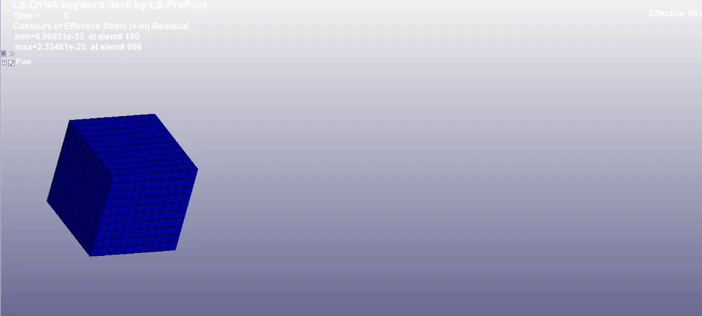
ELFORM-1
Fully integrated solid intended solid for elements with poor aspect ratio with efficient formulation.
ELFORM2
Fully integrated solid elements which reduce the stiffness matrix.
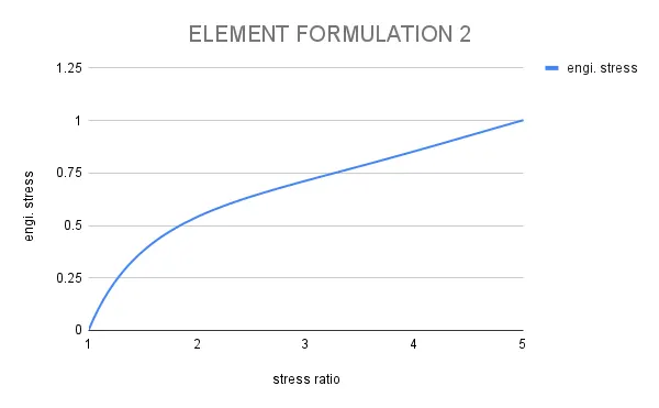
ELFORM-2
Fully integrated solid intended solid for elements with poor aspect ratio with accurate formulation.
CONCLUSION
The result between Engineering Stress and Stretch Ratio is ploted for different formulation there is no significant changes except the computational time, the tensile test of cube is very small stimulation the difference might be noted in big problem eith small aspect ratio.
From the stimulation ELFORM1 has low computational time followed by ELFORM2, where ELFORM-2 has more computational time than ELFORM-1.