Week-6 Calculate the Stretch Ratio by comparing the ELFORM (-2,-1,1,2) with Ogden_Material Model.
AIM :
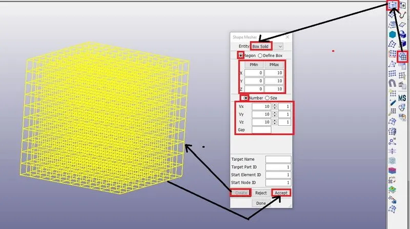
To create a block of 10mm×10mm×10mm dimension with 10 elements for each direction. Simulate the tensile behaviour of the block and compare the results in simulation using ELFORM 1,2,-1 and -2.
PROCEDURE :
1. Import the given material in LS-Prepost.
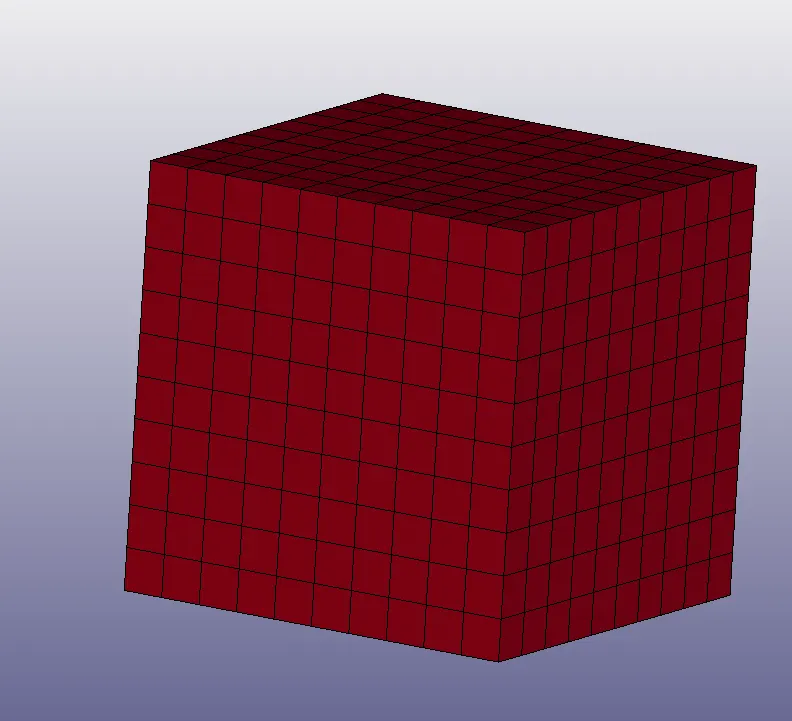
2. Create the required block with given dimensions as shown below
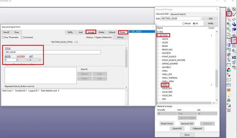
3. Create the section solid to the block as shown below.
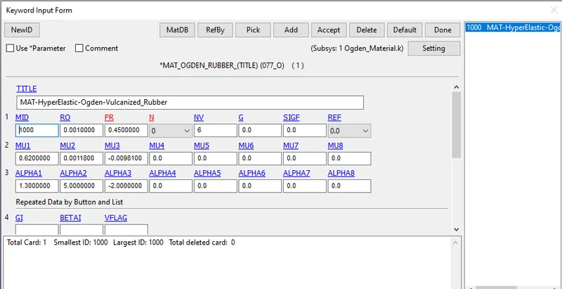
4. Material is already imported as shown below.
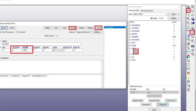
5. Next assign the section and material to the block as shown below.
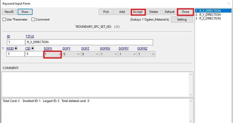
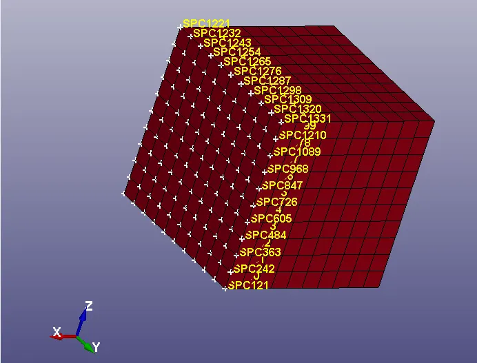
6. Create the Spc boundary conditions for the block as shown below.
Restrict in X-Direction :
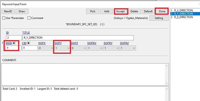
Restrict in Y-Direction :
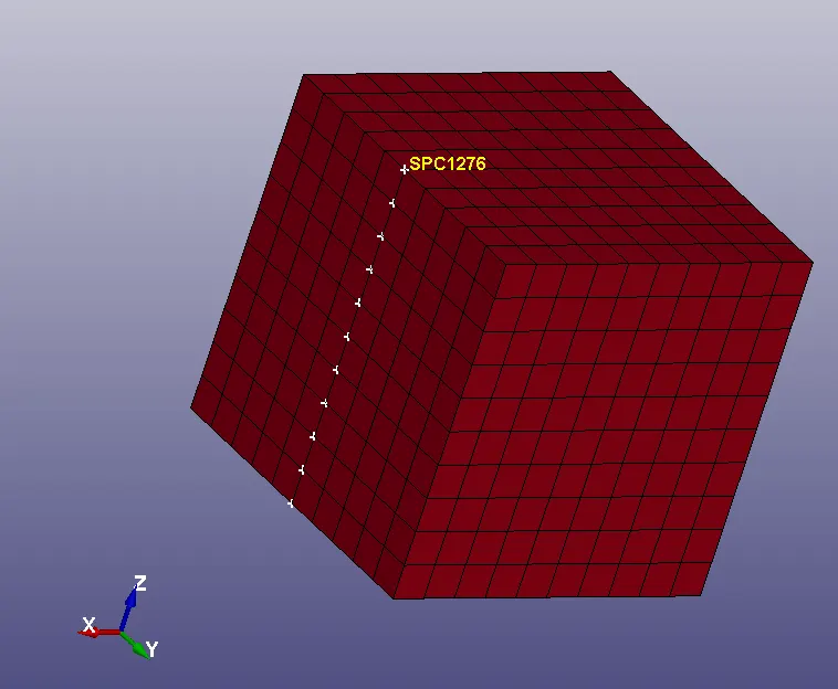
Restrict in Z-Direction :
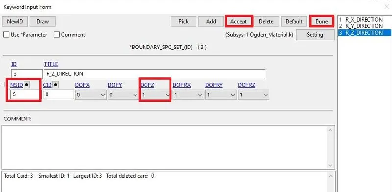
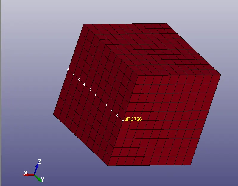
7. Next create the Prescribed motion boundary as shown below.
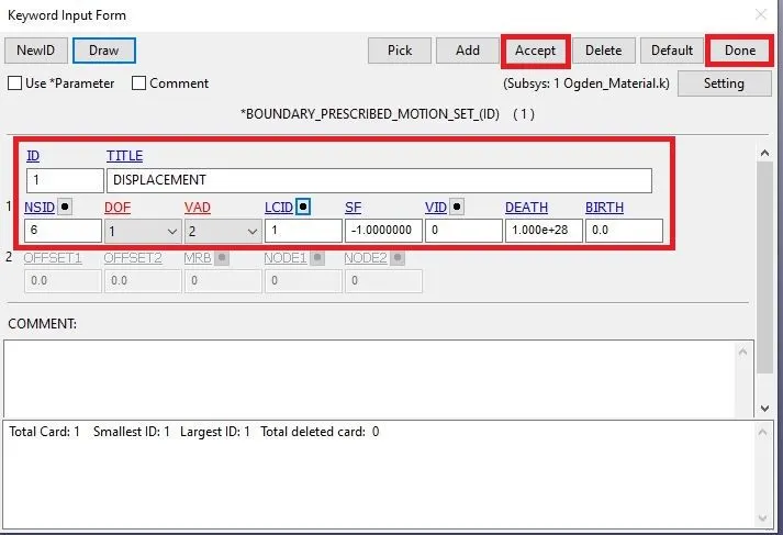
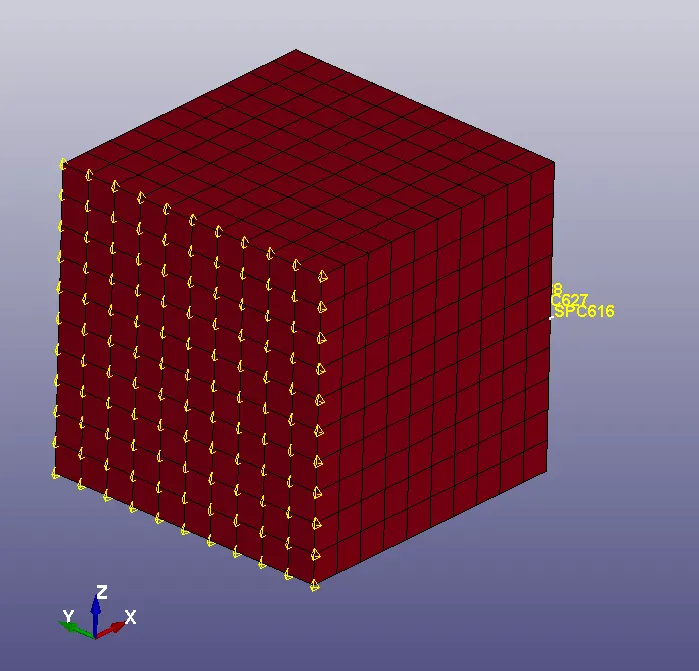
8. Create a curve for a prescribed motion boundary as shown below.
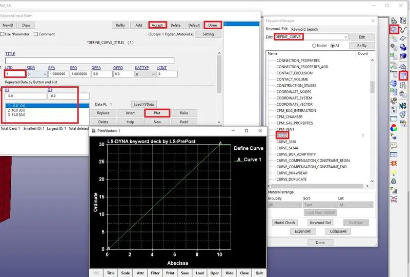
9. Assign the LCID to prescribe motion boundary conditions.
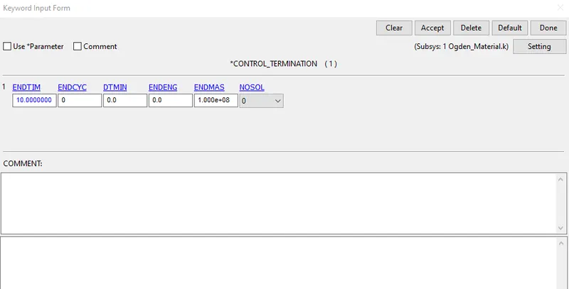
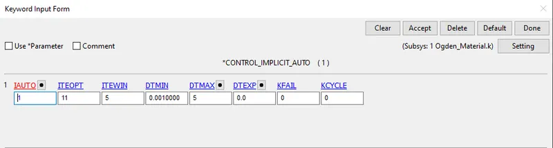
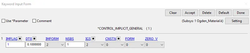
10. Next create the control termination, Implicit auto and Implicit general as shown below.
TERMINATION
IMPLICIT AUTO
IMPLICIT GENERAL
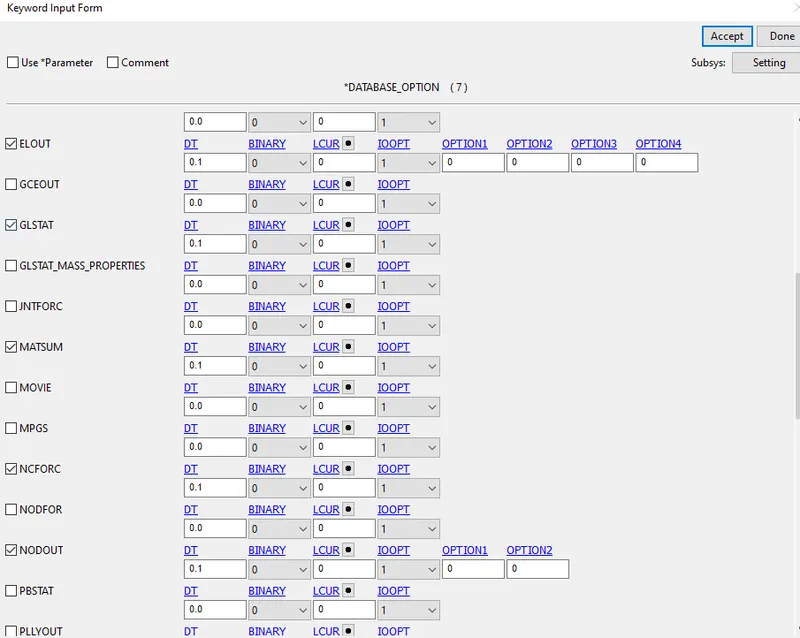
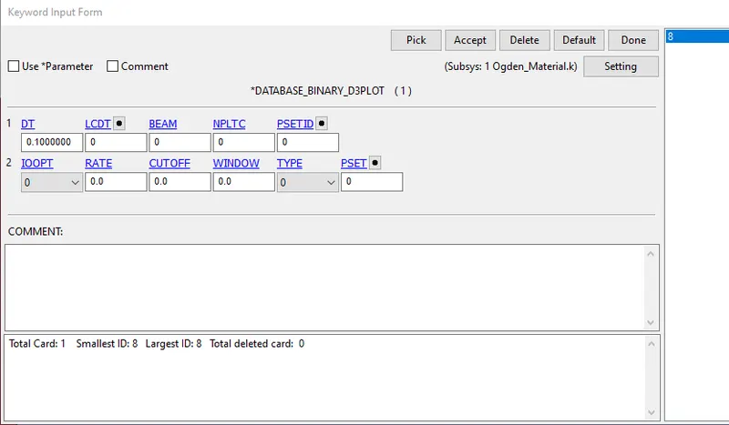
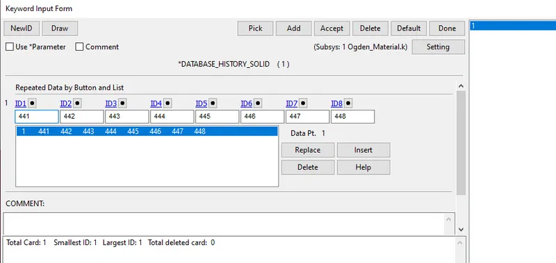
11. Create database outputs as shown below.
ASCII_options
BINARY_D3PLOT
HISTORY_SOLID
11. Next click on the model check icon to check the errors and warnings as shown below.
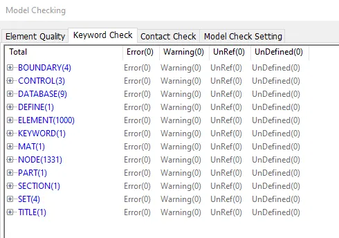
12. Next save the .k file and run the simulation in the LS-Run as shown below.
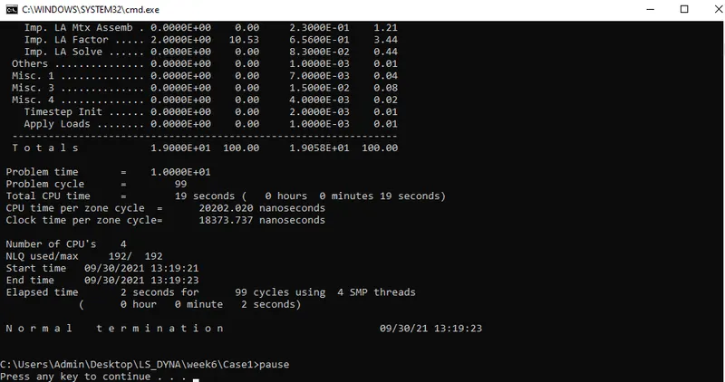
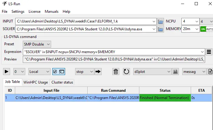
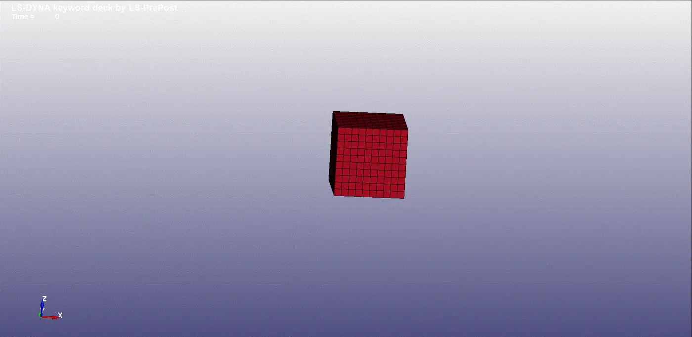
13. Next open the binary plot in LS-Prepost and see the animation as shown below.
CASE 1 :
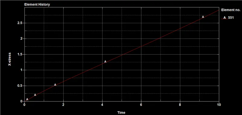
STRESS :
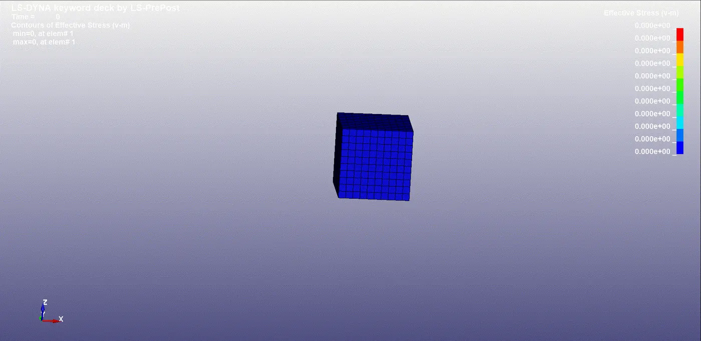
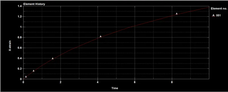
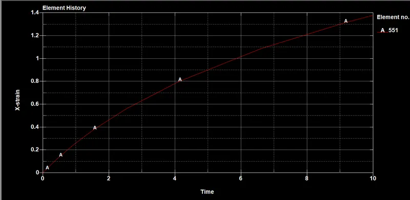
Plot the graphs for stress and strain for the block to save the result.
STRESS GRAPH :
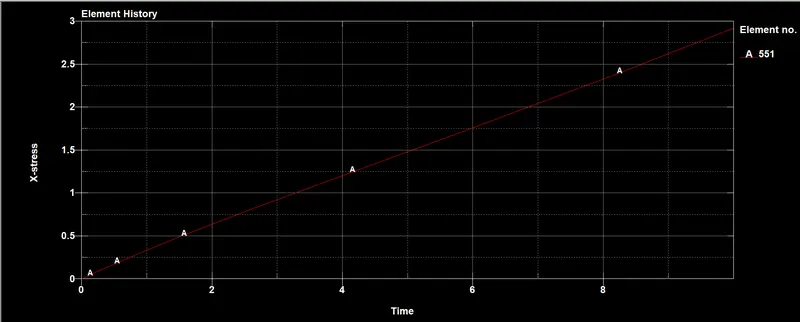
STRAIN GRAPH :
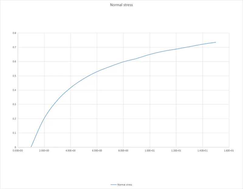
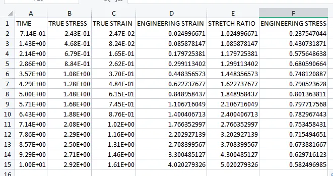
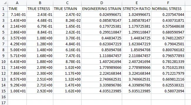
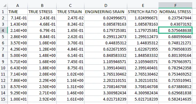
uses the below formulas to find the Normal stress.
Engineering stress (or) Normal stress(σ e) = True Stress(σ t) /Stretch Ratio(λ)
Here,
Stretch ratio(λ) = 1+Engineering Strain(ε)
Engineering Strain(ε) = EXP(True strain)-1
Note:
Take The values of True stress and True strain to the above graphs.
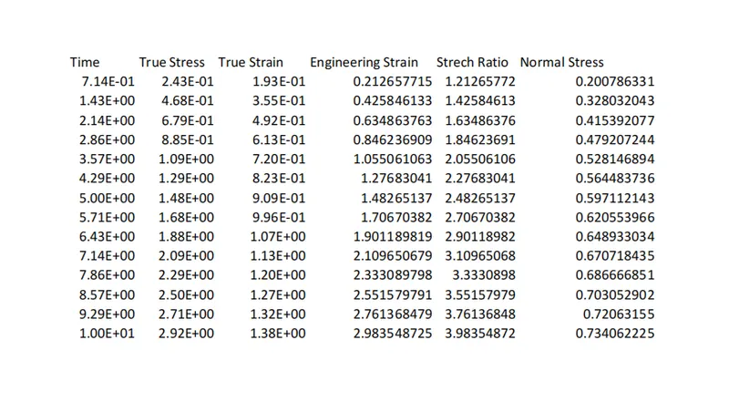
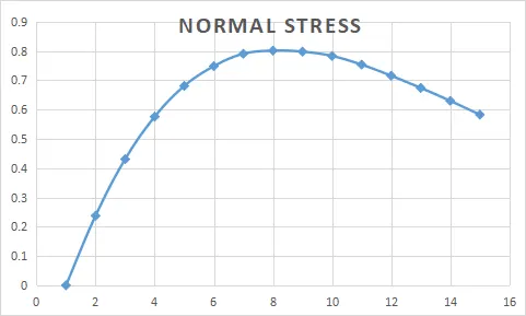
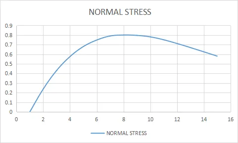
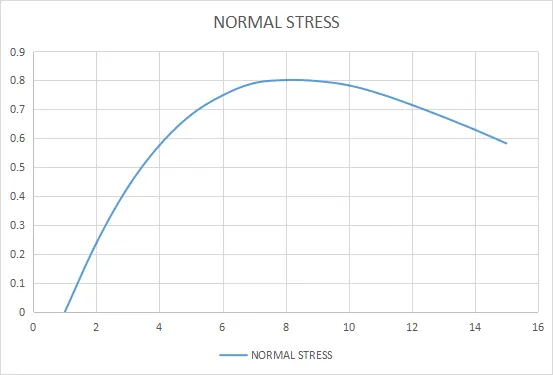
Take the normal stress and Stretch Ratio plot the graph as shown below.
CASE 2 :
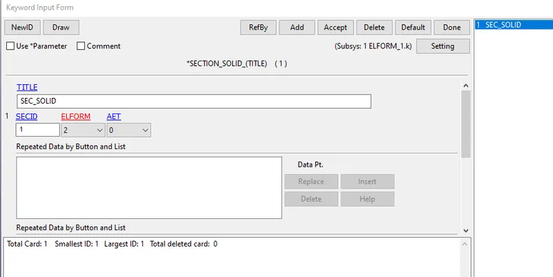
To change the element formulation 1 to 2 as shown below.
RESULT :
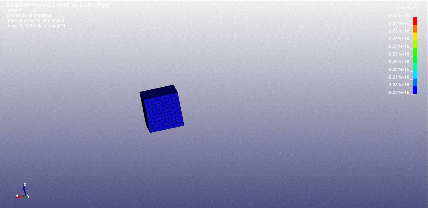
STRESS :
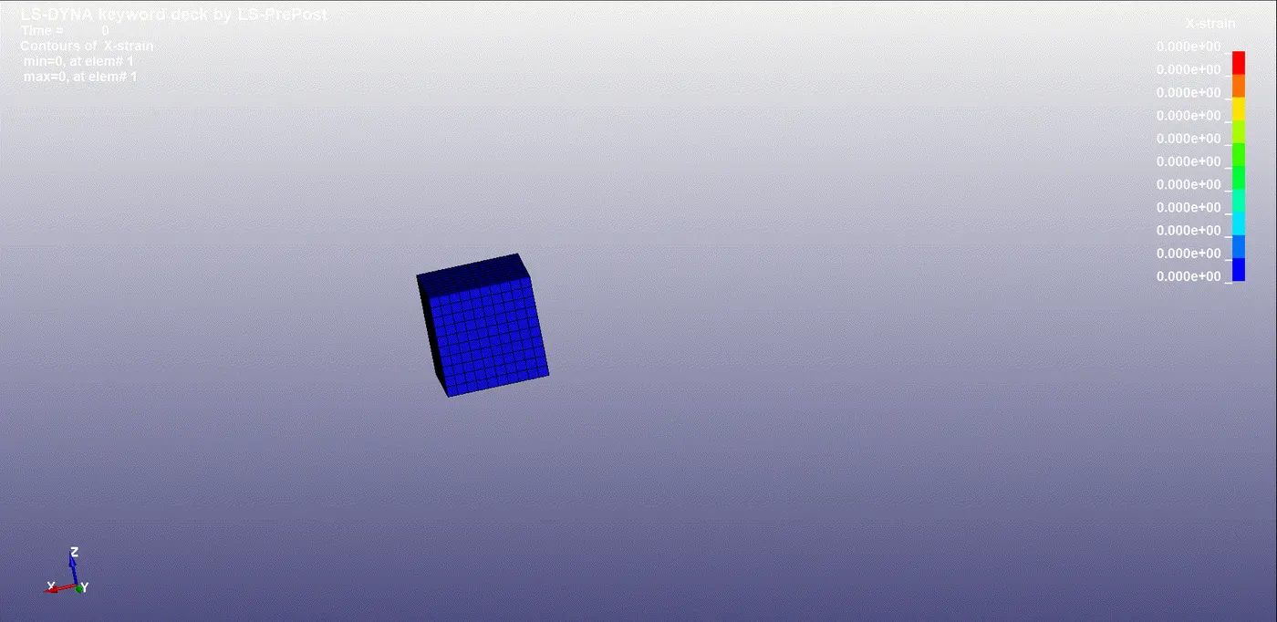
STRAIN :
STRESS GRAPH :
STRAIN GRAPH :
NORMAL STRESS vs STRETCH RATIO :
CASE 3 :
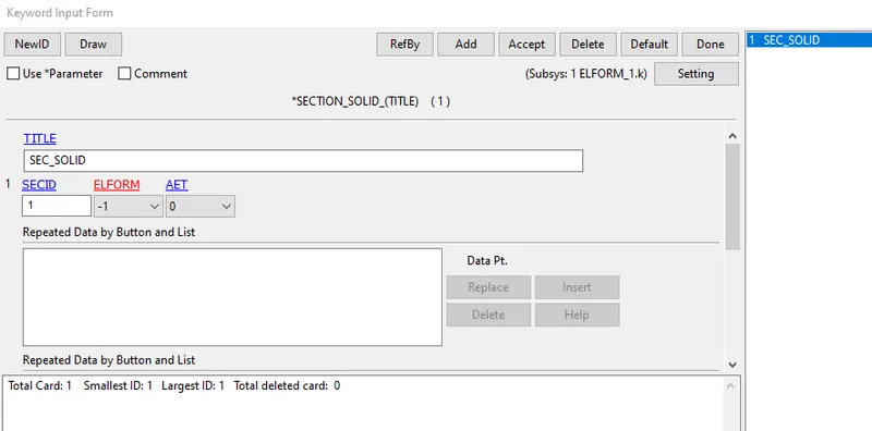
Change the element formulation 2 to -1 as shown below.
RESULT :
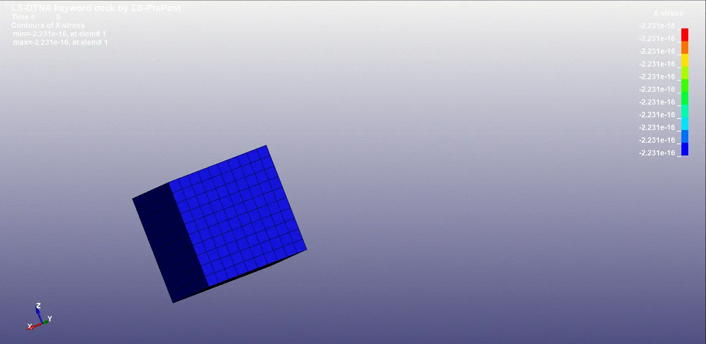
STRESS :
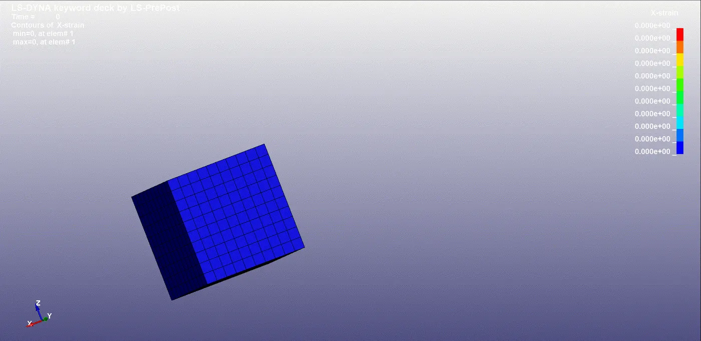
STRAIN :
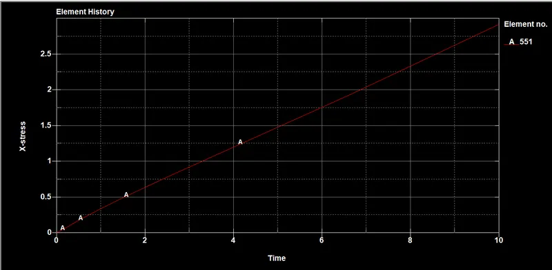
STRESS GRAPH :
STRAIN GRAPH :
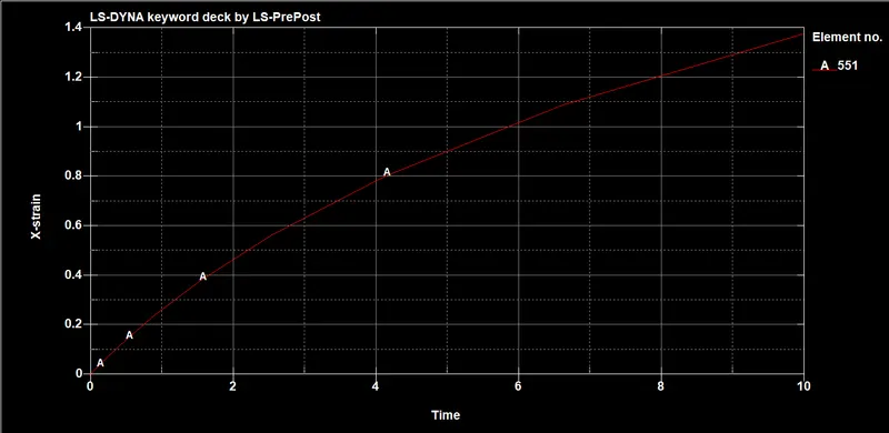
NORMAL STRESS vs STRETCH RATIO :
CASE 4 :
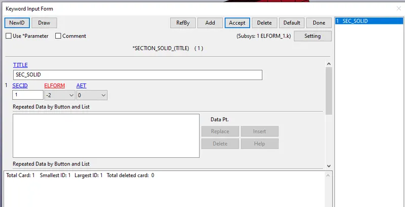
To change the Element formulation -1 to -2 as shown below.
RESULT :
STRESS :
STRAIN :
STRESS GRAPH :
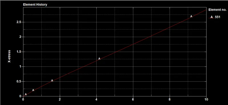
STRAIN GRAPH :

NORMAL STRESS vs STRETCH RATIO :
CONCLUSION :
By changing the element formulation normal stress changes each case as shown below.
Case 1 Element formulation is 1, normal stress is increased gradually.
Case 2 Element formulation is 2, normal stress is decreased at the end of the simulation.
Case 3 Element formulation is 3, normal stress is decreased.
Case 4 Element formulation is 4, normal stress is decreased end of the simulation.