CONNECTIONS FOR THE FE MODEL OF A REAR DOOR USING NASTRAN DECK.
OBJECTIVE:
To give connections for the FE model of a rear door using Nastran deck.
Car door
- A car door is a type of door, typically hinged, but sometimes attached by other mechanisms such as tracks, in front of an opening which is used for entering and exiting a vehicle. A vehicle door can be opened to provide access to the opening, or closed to secure it. These doors can be opened manually, or powered electronically. Powered doors are usually found on minivans, high-end cars, or modeified cars.
- A door itself is a system which houses the door lock mechanism, hinge mechanism, door glass slider mechanism etc and the connection are made using spot welds, seam welds, bolts, RBE2 elements etc.
- To achieve all these, there are different types of connections available in Nastran deck.
- When we have glass type component in the system the connection on those areas are very critical because the glass itself is a brittle material and it cannot be bolted or joined by adhessives.
- The body consists two types of glasses namely front and rear glass. Those glasses are fixed ones and it can be parmanently fixed using adhessives.
- But for the door glass, it will move up and down, there should be a mechanism defined which helps for that movement. The window motor will not be modelled but it will be captured as a fixed mass in FE analysis.
- Usually the glass will be modelled in a closed position.There is a black beed present and the glass slides up and down through that rubber beed. These beeds are called weather strips which restricts the vehicle from the outside atmosphere.
- The conenction which deploy at these position should be rigid as possible also it should ensure the damping coefficient of the physical model.
PROCEDURE:
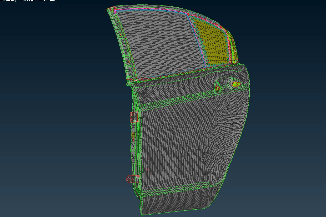
- Open ANSAv19.1.5 and import the given .nas file into the workpage. File>Input>Nastran.
-
Use the FE perimeter from the mesh module which recognizes FE Perimeters automatically and creates the respective entities in the database.
Representing bolt connection
- Bolt connections are used to connects two or more holes either its shell or solid mesh. Also if there are two mating parts there is no seam weld in between then the parts are joined by bolts.
- If the hole is made up of more than four nodes providing the hole with a zone of element (washer) is preferable. If there is no washer present in meshed model, it can be formed using mesh module>shell mesh>zone cut.
- Bolts can be represented as a manual rigids and automated connection.
- When representing it as an manual rigids, RBE2 elements can be used. Nastran decks>Elements>RBE2.
- RBE2 can be classified as single node and many node (cluster) RBE2 where there exists a master node and slave node in them. Based on the position and distance of the slave node Ansa identifies the COG of that hole and by default it will show the location for the master node.
- The image below shows the creation of RBE2 element using many node (cluster).
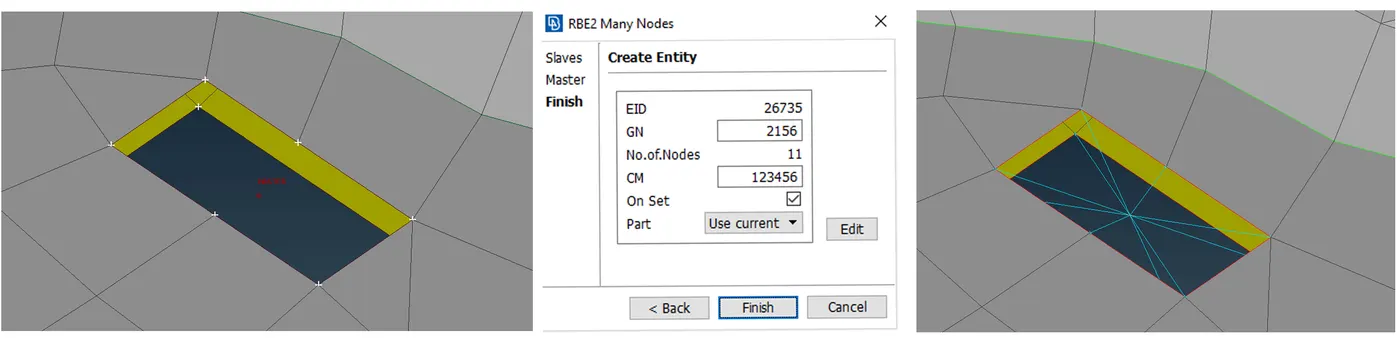
- To connect two component by bolts using manual rigids, RBE2 elements are created seperately for each hole and then the master nodes of the two hole is then connected using a two node RBE2. Thus a physical representation of bolt and nut can be achieved.
- For creating an automated bolt connection a 3D pont on the hole has to craeted. Topo mudule>point>ON COG.
- This 3D point is now conveted to connection type as bolt from convert option available in the Assembly toolbar.
- To realise this connection manager is opened and select the bolt connection point created earlier and providing the necessary information required as per our criteria.
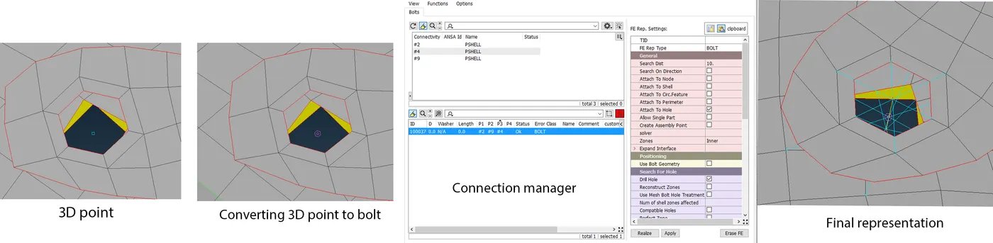
- Doing this with manual method takes more time. While connecting one sub-system to other sub-system the automated connection wont work , it has to be established manually.
Hinge connection
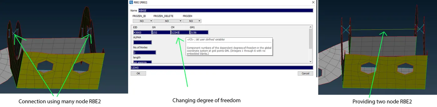
- In NVH hinge is represented as RBE2 element. The hinge should not restict the motion in all degrees of freedom because the door will have to open in a particular direction.
- First the elements are rigidised using cluster RBE2 as shown in the figure and a connection between the master node is established using two node RBE2.
- To remove the constrain in Z direction (rotational) the value for CM is given as 12345 (for this current model).
Door handle
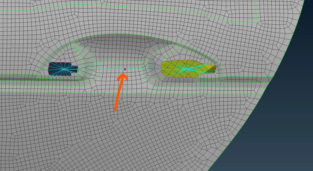
- Here the elements are first rigidised using RBE2 element and connected using two node RBE2 element.
- Door will be generally modelled as a mass element and we define the mass at the master node.
- Generally the mass of the door is around 100g.
- In ANSA we need to assign the values in tons.
- The mass can be assigned from, Nastran deck>Elements>CONMi>CONM2>select the node where mass to be applied>Enter the value for the mass in tons>ok.
Representing Spot weld
- Spot welding is one form of resistance welding which weld two or more sheet metal together without using any filler material and applying pressure and heat to the area to be welded.
- Its used to connect two elements at a point.
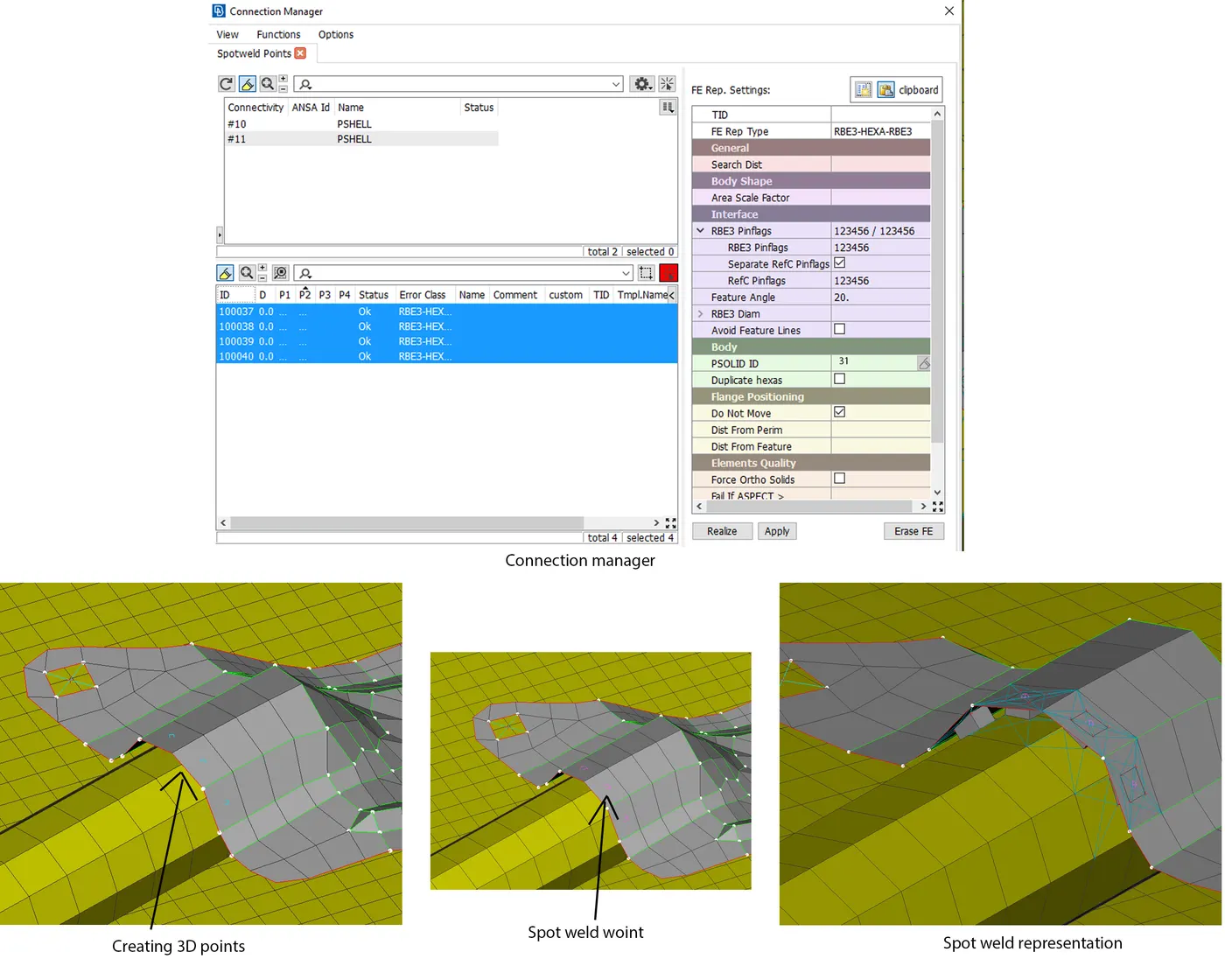
- For representing spot weld a 3D point is created netween the elements using on COG tool. The 3D point is now conveted to spot weld point using the convert tool from assembly toolbar. The model is then realised from connection manager.
- Here RBE3-HEXA-RBE3 was used as FE representation type and value for RBE3 pin flanges and Ref c pin flanges were given as 123456 (Constrained in all direction).
Seam weld
- Seam welding is the joining of work pieces made of similar or dissimilar materials along a continuous seam.
- Its mainly used in structural load carrying areas because it provides more structural rigidity.
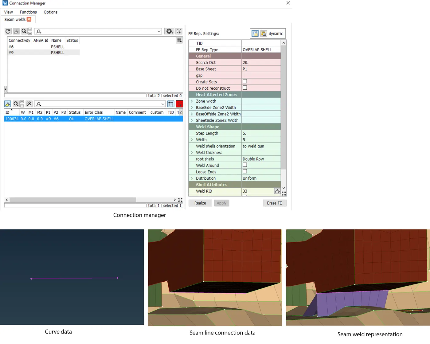
- For representing seam weld we need to create a curve data and then its been converted to seam line data using convert option in assembly toolbar. The curve data can be created using the curve tool or Feat2curve. The The seam line data can be realised from the connection manager.
- Seam weld can be represented in two ways using shell elements as overlap shell and Y-Joint shell.
- Y-Joint shell is used when the two parts are parpendicular to each other.
- Here the two parts are parallel to each other Overlap shell option is used as FE rep type for this area.
- After doing seam weld the mesh will get distorted and further correction has to done to have a good mesh flow.
Door window connection
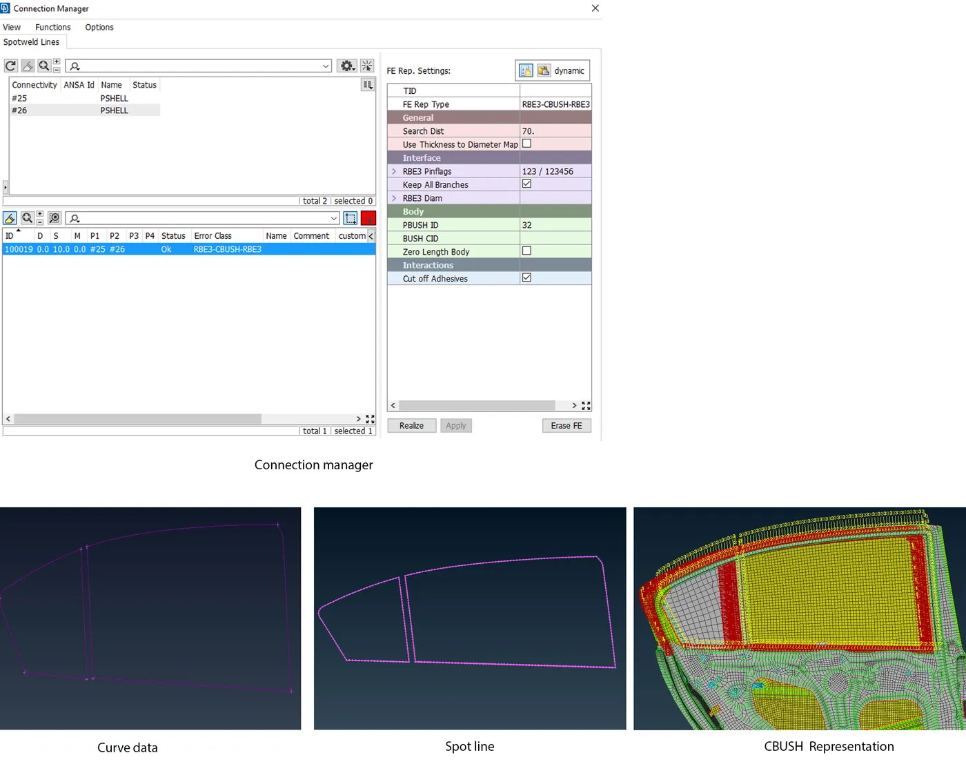
- The conncetions are critical in the areas where there is a glass type component because glass is a brittle material and it cannont be bolted or joined by adhessives.
- The bottom line of the window is called as glass line. Here we are having damping elements on either side of the doors but on the other three sides we are having connections only at outside.
- To represent this connectoin a curve data is been made using Feat2curve from mesh module and then converting it to spot line from assembly toolbar. The spot line is realised from the connection manager. It should be noted that while deploying the connection each curve have to taken seperately for realising the connection (Bottom,top,left,right). Also assign the values for the space (s) between two bushes in the connection manager and give a tick mark to 'keep all branches' coloumn.
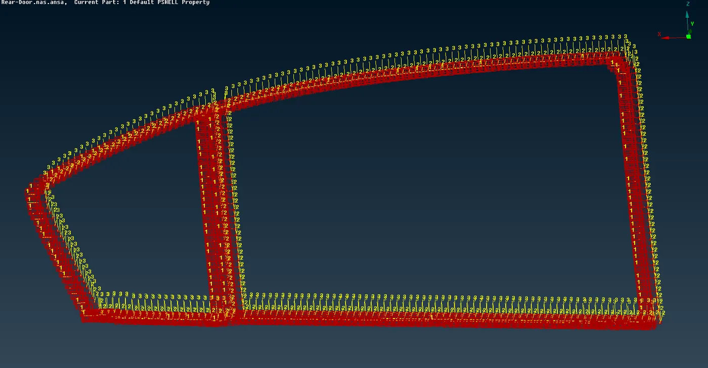
- Here RB3-CBUSH-RBE3 is used as FE rep type. RBE2 element does not have any property but for CBUSH the property is mentioned in the Pbush property card. CBUSH is generally a spring element, Where its having the damping coefficient and stiffness values in three direction. While creating Bush ID values for stiffness has to mentioned (as per solver requirement).
- After this CBUSH representation there will be orientation a issue which creates some deviation in results while simulating. We need to make the local coordinate (vector direction) of the CBUSH alinged with the global coordinate of the vehicle.
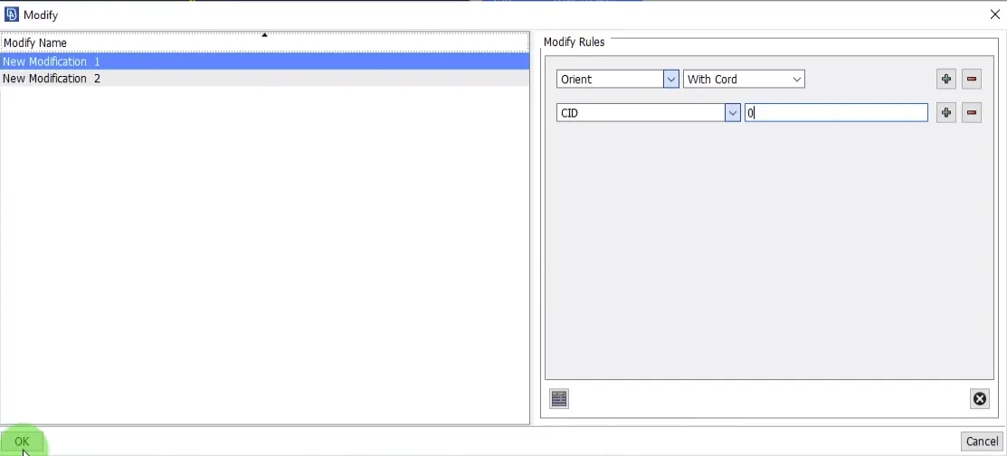
- For that we need to open the CBUSH window from the database(F12) and then the orientation and CID has to be switched ON. Since there are lots of CBUSH elements created its very difficult to change each of them one by one. To correct the orientation at one shot, we need to select all the CBUSH>right click>modify>(changes the values as shown below)>ok.
Glass and frame area
- In FE modelling the window motor is not modelled, but it will be just captured as a fixed mass. These are the some of approximation taken during FE modelling.
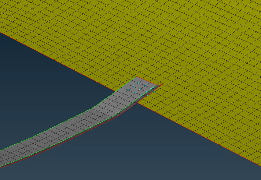
- Here the tray(surface) is been extended towards the window using MV free tool from mesh module and its been rigidised using RBE2 elements.
The conections to the remaining areas of the model is done using the suitable connectors.
RESULT:
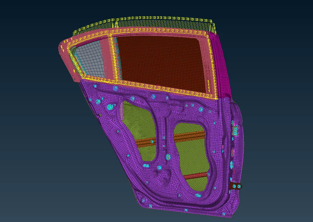
The connections to the given FE model of a rear door is done sucessfully using Nastran deck.
LEARNING OUTCOME:
- 1D elements and different types of connections.
- Assigning mass to a rigid body.
- Working mechanism of a car door.
............................................................................................................................................................................................
File: https://drive.google.com/file/d/1pgcU63ZkKY9dJ90gK881zRescF10Oqph/view?usp=sharing