Week 6: Rear Door of a Car
Aim:
The main objective is to give connections for the Rear Door of a Car.
Methodology:
The methodology is to follow the step by step process to get the successful model.
- Checking the Model
- Giving the Proper Mesh flow
- Assessing the PID
- Giving the PID
- Giving Connections
- Checking or any errors present
Theory:
- Rear Door:
The rear door is a sub-system of the car. A car door is a type of door, typically hinged, but sometimes attached by other mechanisms such as tracks, in front of an opening which is used for entering and exiting a vehicle. A vehicle door can be opened to provide access to the opening, or closed to secure it. These doors can be opened manually, or powered electronically. Powered doors are usually found on minivans, high-end cars, or modified cars.
- NASTRAN:
NASTRAN is a finite element analysis (FEA) program that was originally developed for NASA in the late 1960s under United States government funding for the aerospace industry. The acronym for NASTRAN is NASA Structural Analysis. It is the Frequency at which the body vibrates.
- Connectors:
Connectors are the connections that are used to connect the two parts of the system. The Connectors can be in the form of Rigid Body connection, Bolt connection, and Weld connection.
The connections play an important role in analyzing the model to run smoothly. The connections data in the normal CAD is called the raw data from which the connection data should be read into the ANSA format and then the connections are deployed.
Procedure:
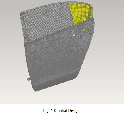
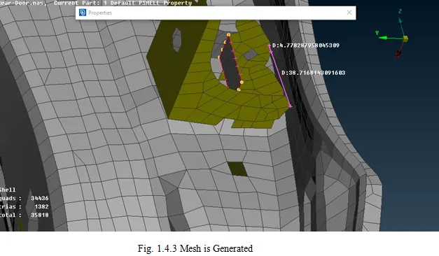
The given model which when opened already has a mesh done.
- Checking the Model:
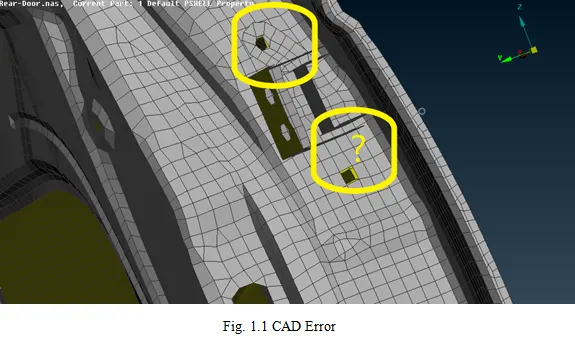
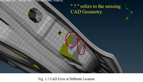
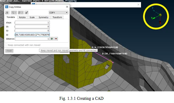
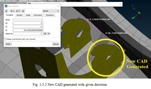
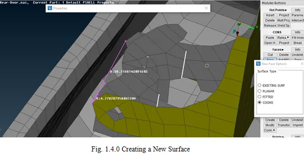
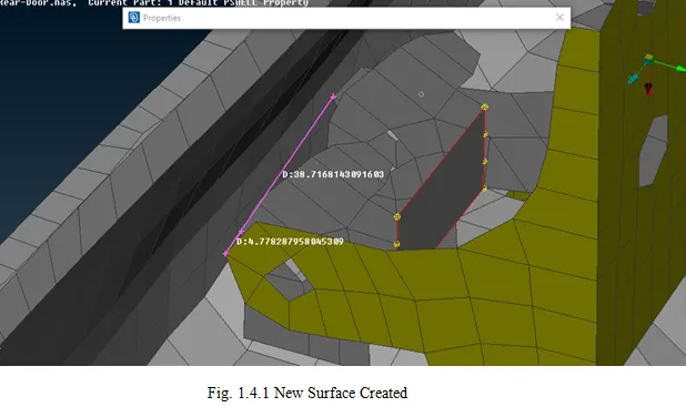
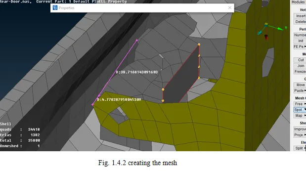
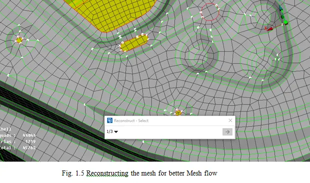
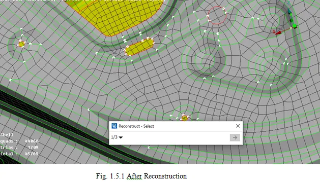
Initially, to give a proper connection the design should properly mesh and there shouldn’t be any CAD errors.
- PID Assessment:
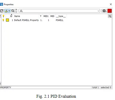
Check the PID Manager to check that all the parts of the model are in orders.
- Giving the PID:
PID is to be given for each part as it is easy to understand which part is connected with the other.
- Connections:
1. For Bolt connections:
Bolt is a rigid representation. In NASTRAN, RBE2 is used for NVH Domains.
In Topo Deck, Points >> ON COG >> Click OK
Convert >> 3D Points >> Select Entity >> Bolt >> Click OK
Connection Manager >> Select bolt part >> Select the Parts to be given the connection >> Select FE Rep Type >> Bolt >> Give Search Distance >> Click Apply and Realise.
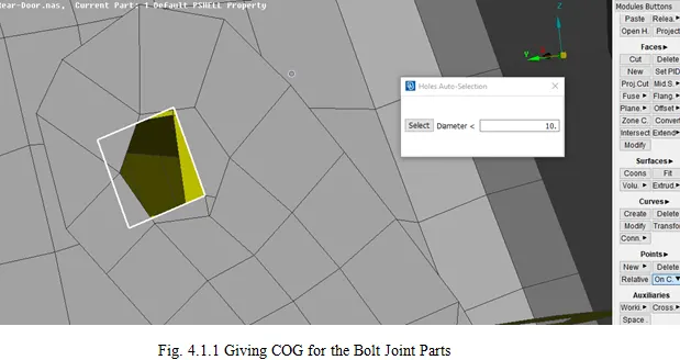
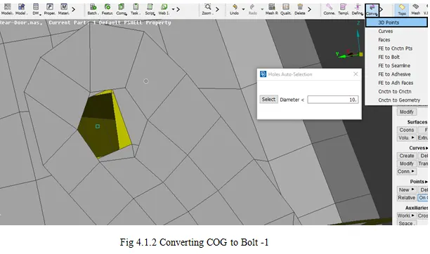
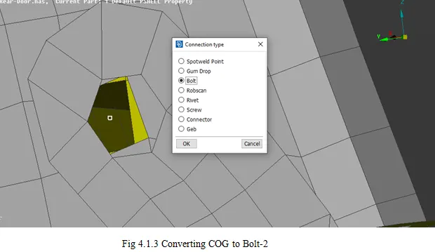
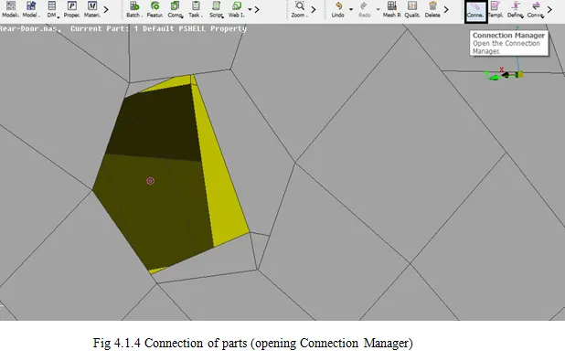
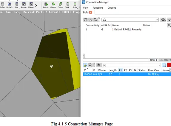
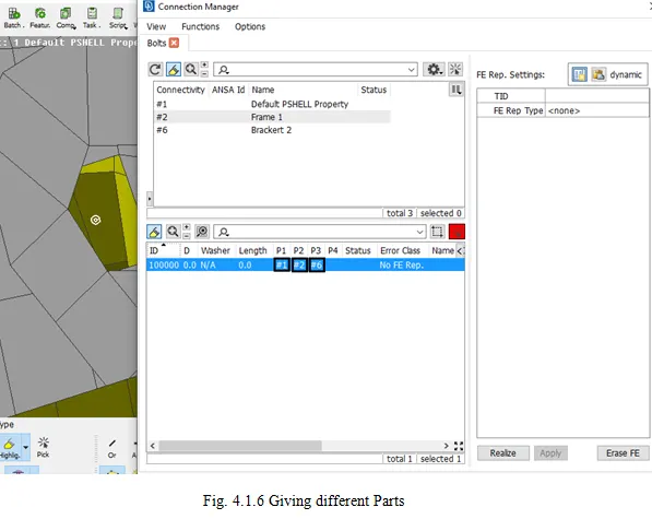
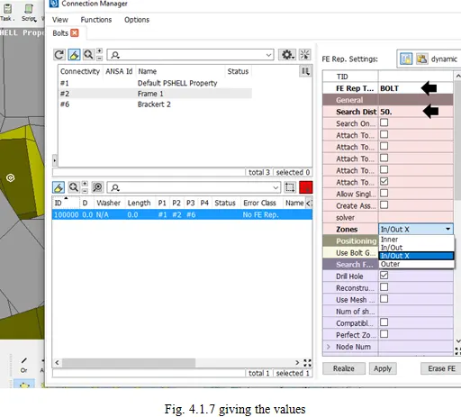
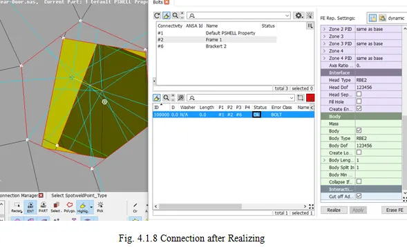
2.Many Nodes RBE2:
- In the NASTRAN Deck, In the Elements Module, RBE2 is clicked to give a connection to the parts.
- The nodes are selected at the free edge and then a Master Node is generated as a COG then creates an entity to save the connection in new elements.
- It is similar to the PID generation.
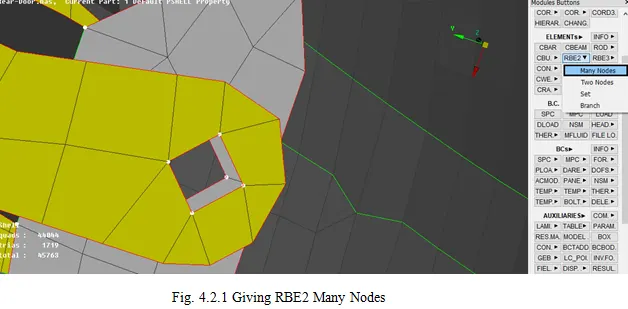
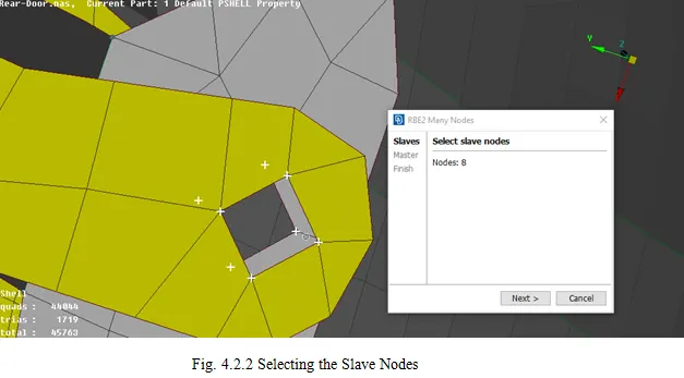
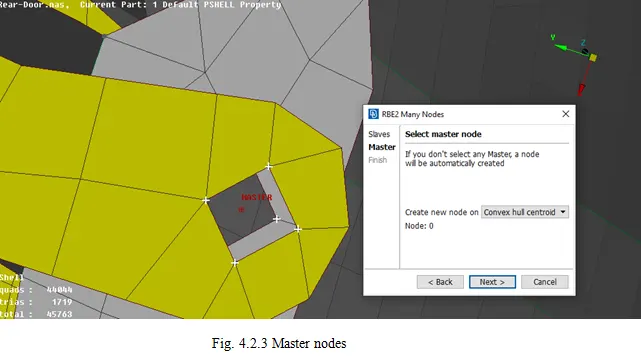
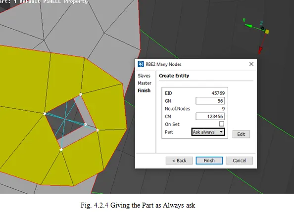
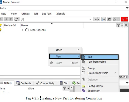
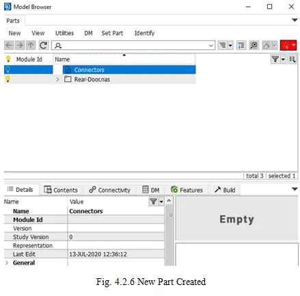
Elements >> RBE2 >> Many Nodes >> Select Slave Nodes >> Select Master Node >> Create Entity >> Create New Part ID.
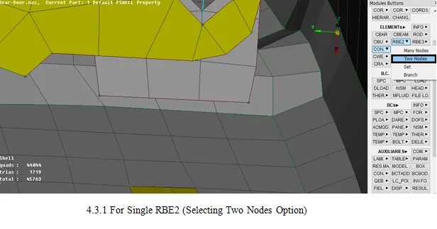
3. Single Node RBE2:
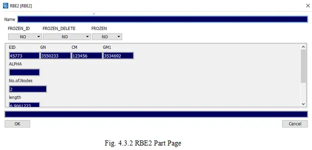
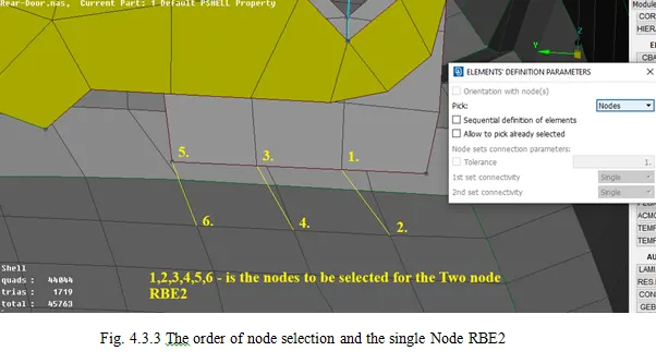
- It is similar to Many Nodes RBE2 but the only difference is that the only two nodes are selected from each of the parts which are to be collected.
Elements >> RBE2 >> Single Node >> Select the Nodes >> Click Ok.
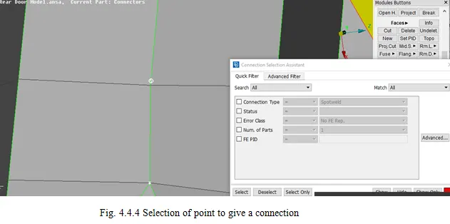
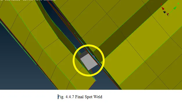
4. For Weld Joints:
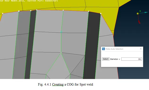
The weld joints are generally given or the data related to them is given but in cases, the joints are not given, the connection can be drawn as per the design knowledge. In Topo Deck, points
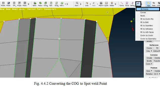
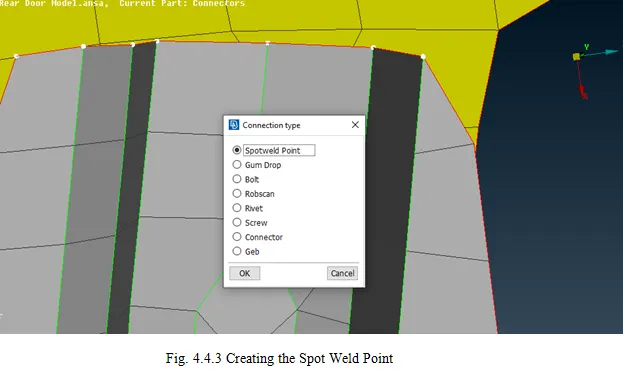
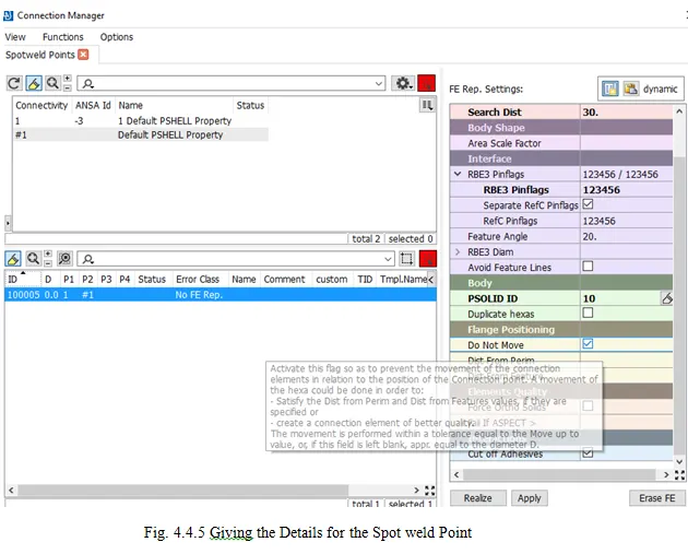
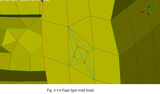
Select ON COG >> Select an entity >> COG is created >> Go to Convert >> 3D points >> Spot Weld >> Define the connection >> Select FE Rep type >> RBE3- HEXA-RBE3 >> Give search Distance, RBE3 Pin-flags as 123456.
Here, 123456 are the Degrees of Freedom. All the Degrees of freedom is given as 123456 and it means that the weld is fixed constraining all the direction of movements (Degrees of Freedom)
5. For the Door Handle:
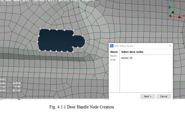
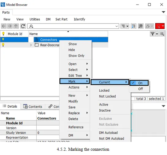
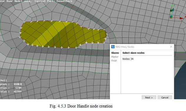
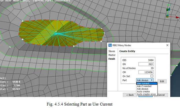
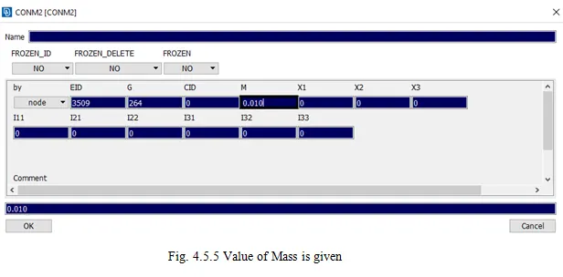
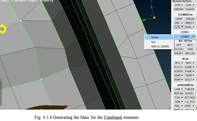
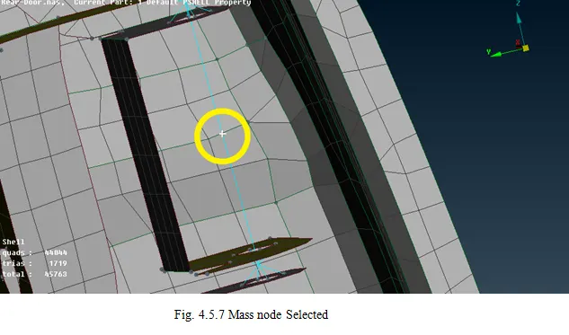
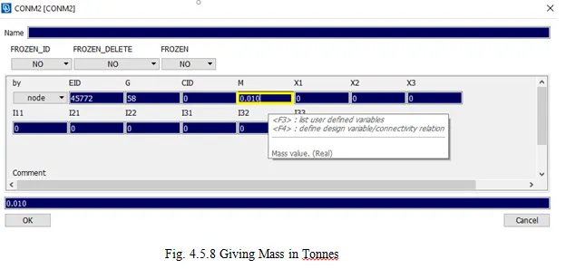
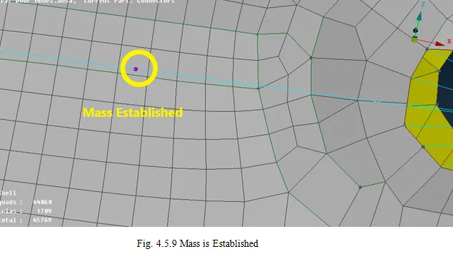
The door handle part connection is made of the cluster RBE2, but the part which when connected will have some mass i.e. the mass of the hand when pulled or pushed. To give the mass to the Part, the following procedure is used.
In NASTRAN Deck >> Elements Modules >> CONMI >> CONMI2 >> NODES >> New Tab Opens >> Give M Value (M is mass in Tonnes) >> Click Ok.
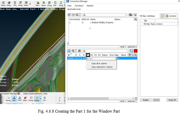
6. For Window Part:
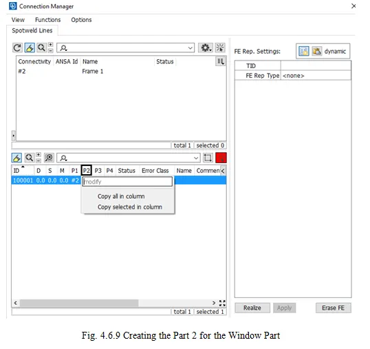
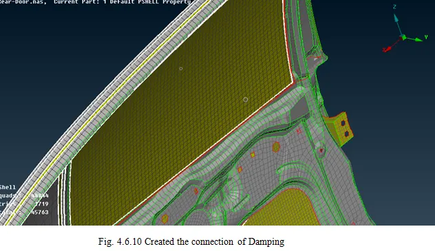
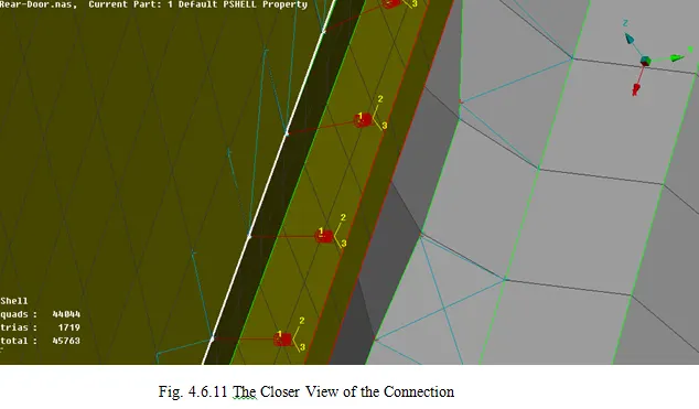
To give the Connections near the window parts, there is a process of getting the work done.
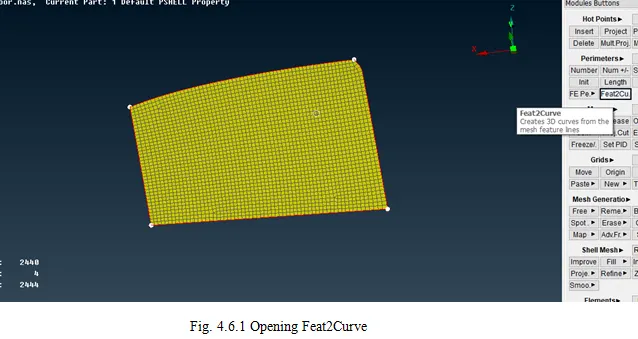
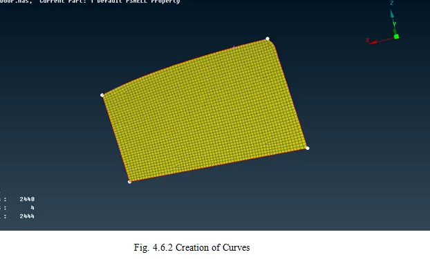
Initially, a curve is created and the Curve needs to be converted.
In Mesh Deck >> Perimeters Module >> Click Feat2Curves >> Create a Curve by selecting the entity.
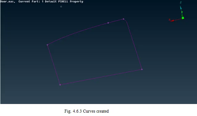
Go to Convert >> Curves >> Select Spot Line
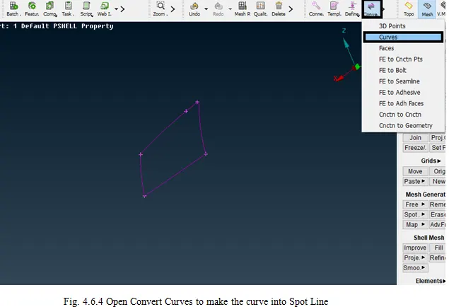
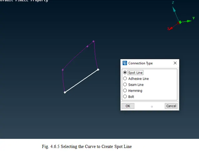
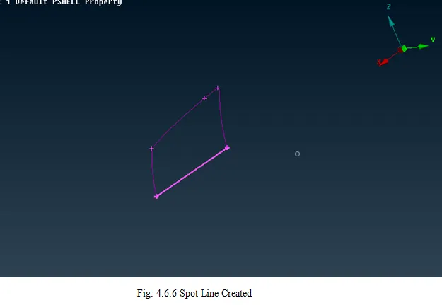
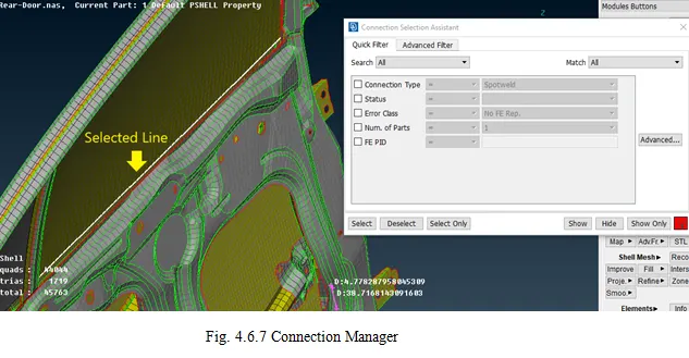
Go to the Connection Manager >> Select the Spot Line >> Give P1 and P2 >> Select FE Rep Type >> RBE3-CBUSH-RBE3 >> Give Search Distance, Select the Option “Keep All Branches” >> Give New ID >> Click “ ? ” (Without “ ”) >> New Window Opens >> Create New ID >> Click OK.
7. Aligning the Coordinates:
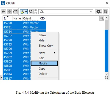
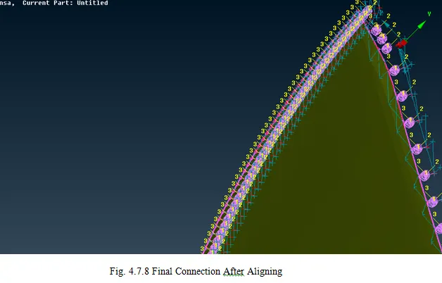
Once the Damping connection is done, the alignment is to be made with the global Coordinates to make connection stable.
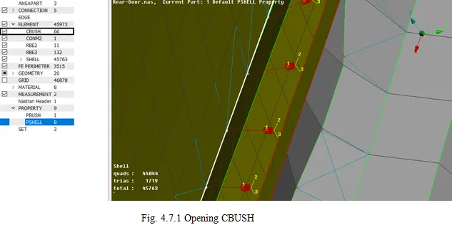
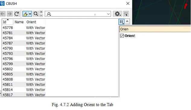
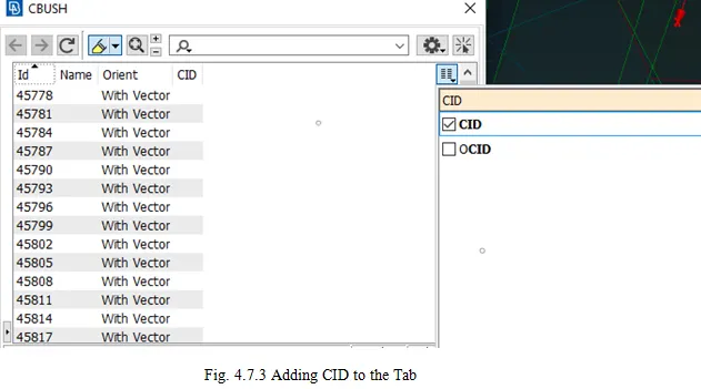
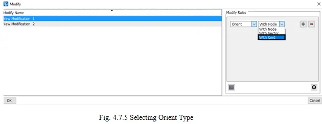
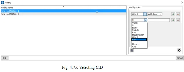
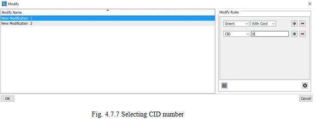
In Database >> Select Elements >> CBUSH >> In Search, Click Orient, CID >> Select All >> Modify >> Orient with Cord >> CID = 0 >> Select OK.
Terms used:
- NVH:
NVH is an abbreviation of Noise, Vibration, and Harshness of the model or design. It is done in the frequency domain using fast Fourier transforms.
- Rigid Body:
A rigid element is a link from one node to one or more other nodes, where the motion of the node or nodes is governed by the "degrees of freedom" you choose to connect. A rigid element is a constraint equation rather than an actual element, but for practical purposes that matter little, except for the tips to avoid common errors with rigid elements.
- RBE2:
RBE2 is known as Rigid Body Element of the form-2. RBE2 is used to connect mesh sets. It transmits the displacements.
- Master Node:
It is an independent node that doesn’t depend on the entities.
- Slave node:
It is a dependant node. It behaves the same as the master node.
- Cluster RBE2:
Cluster RBE2 is formed when two free edges which are of different parts are selected together as a Many Node RBE2 then the resultant is formed as the cluster RBE2.
- RBE3:
RBE3 is known as the Rigid Body Element of the form-3. RBE3 is also similar to RBE2 and the only difference is that RBE3 transmits the Loads (MPC forces)
- MPC Forces:
MPC reaction forces are separated force components dealing with RBE2 /RBE3 connections. They deliver the reaction forces which are necessary to keep the native element deformation state in equilibrium without the RBE-elements. Therefore they are reaction forces
- RBE3 –Hexa- RBE3:
It is used when the weld joint is not given. It is used to create the connection of the Hexa type of element which is a solid (Typically). It doesn’t need to modify the panel mesh. It does have a good correlation in NVH. It is a little stiff, affected by shell mesh size.
It has the over-estimated force and moment and an under-estimated durability.
- RBE2 Vs RBE3:
Both elements "look" the same, in that they have a single node connected to one or multiple other nodes. The difference is that the RBE2 element adds stiffness to the structure, while RBE3 elements "distribute forces" around the connected nodes, without adding any stiffness.
A rigid element can be as simple as two nodes connected at coincident locations (although it would be very unusual to use an RBE3 in that configuration), through to the more common appearance of a "spider" or "sea urchin" connection, or any arbitrary connection of one to multiple nodes.
- CBUSH:
The generalized spring-damper element CBUSH is a structural scalar element connecting two non-coincident grid points, or two coincident grid points, or one grid point with an associated PBUSH entry. This combination is valid for any structural solution sequence.
CBUSH is a spring connection that has damping co-efficient, stiffness, or in a general term which can move in three directions.
- CONMI2:
CONMI means Concentrated Mass inputs. It is defined to represent the mass of the rigid enclosure.
Errors:
There are no errors faced since it is just the connections, the knowledge regarding the connectors is required to know where the connection is given.
Results:
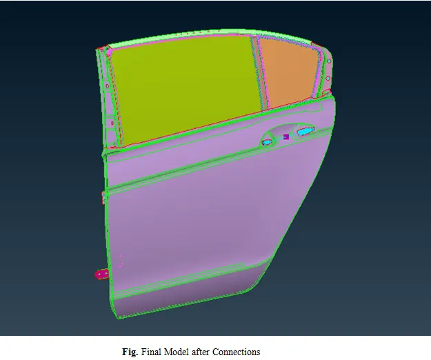
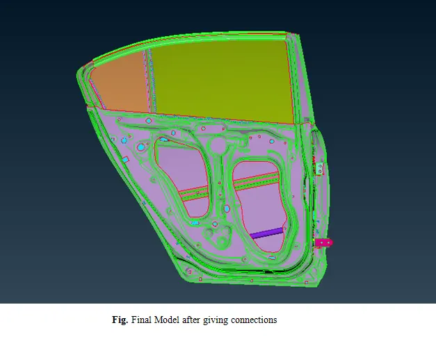
The Connection is established for the given Rear door.
Learning Outcomes:
The learning outcomes for this model are as follows
- Checking the Model and Analysis of the model.
- Giving the Different Connections to the model.
Links Provided:
The terms and the details given in the report are written by own and some of them had to be researched since all the knowledge can’t be learned at the time, some things need to be researched to get the basic idea of the topic.
Connections Types: http://web.mit.edu/4.441/1_lectures/1_lecture13/1_lecture13.html
RBE2 Vs RBE3: http://www.endurasim.com.au/wp-content/uploads/2015/02/EnDuraSim-Rigid-Elements.pdf
CONMI: http://www2.me.rochester.edu/courses/ME204/nx_help/index.html#uid:id471471
Google Drive Link: Rear Door model With Connections