Week- 5 - Solid meshing
AIM - Perform geometry clean-up and generate a Volume Mesh (Tetra) for the Rear View Mirror Component by satifying the Quality criteria.
OBJECTIVE -

PROCEDURE -
1. GEOMETRY CLEAN-UP:
Topology and Geometry Clean-Up must be Performed to proceed further in meshing the component, when the topology is performed a few triple-con errors occur and they can be
resolved by selecting all the defects and right click > fix.
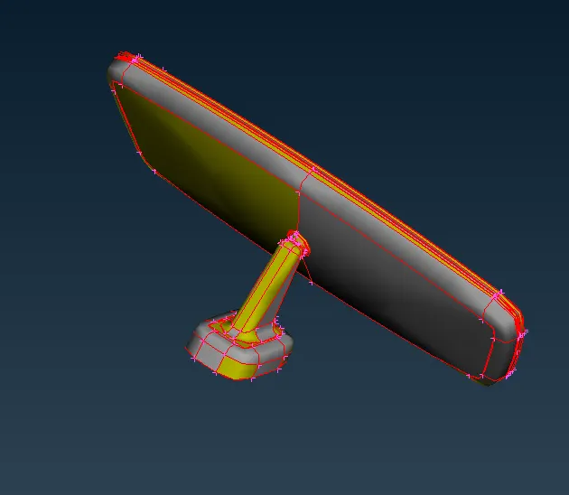
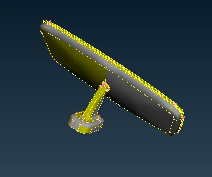
Fig - 1 : Before Topology Fig -2 : After Topology
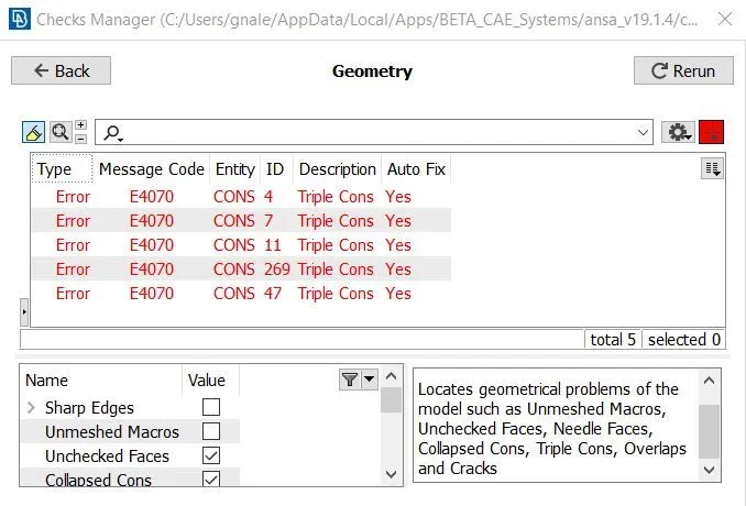
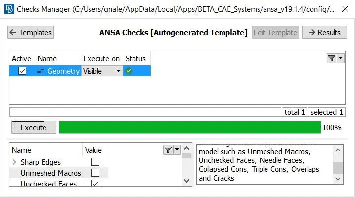
Fig - 3: Before Geometry Clean-Up Fig - 4: After Geometry Clean-up
2. QUALITY CRITERIA:
We have to input the given mesh parameter values required for the component and the Quality criteria includes only min (0.5) and max (2) length in Shells and Collapse (0.2) in Solids.
Also, To assign and adjust the target length, we need to go to mesh module and click on Parameter > Length. This makes the resolution of the cons tobe 'fine' and the length must be 1mm.
The Mesh Parameters and Quality Criteria should be set-up as follows:
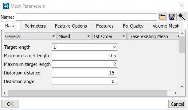
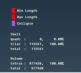
Fig - 5: Parameters
3. DEFEATURING:
In-order to match the Quality criteria, some of the cons needs to be suppressed using the cut and join tool to avoid resulting in minimum length error. This method is known as Defeaturing.
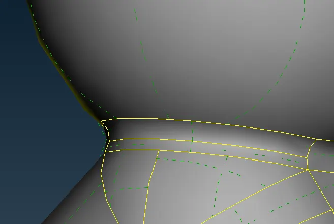
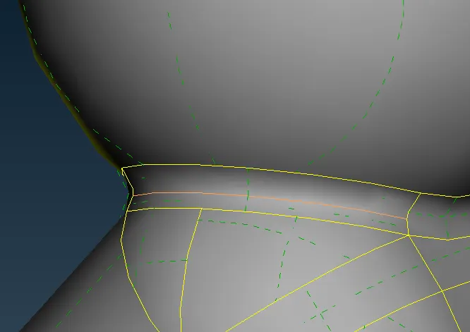
Fig - 6,7: Region I where defeaturing is performed by supressing cons.
-In Fig-8, The region near the circular edge will fail for min length criteria, to avoid that some defeaturing has to be performed.
- In Fig-9, generate two middle curves between the 4 cons using Curves > Middle.
- In Fig-10, we have generated a new face using Faces > New > Cons and delete the existing faces including the fillet as they do no pass the Quality criteria.
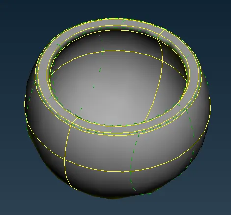
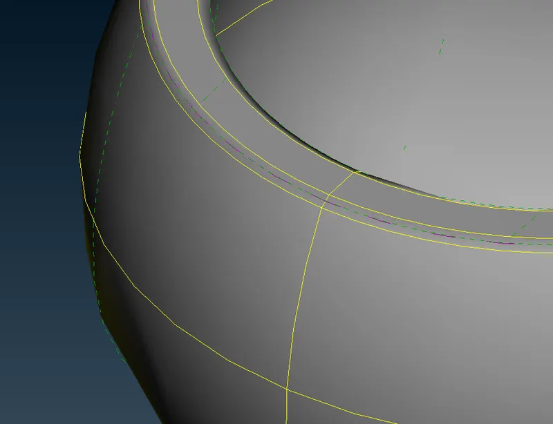
Fig - 8: Region II requiring defeaturing Fig - 9: Generate middle curves
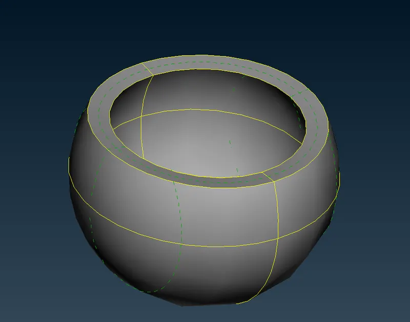
Fig - 10: New face generated
4. MESHING:
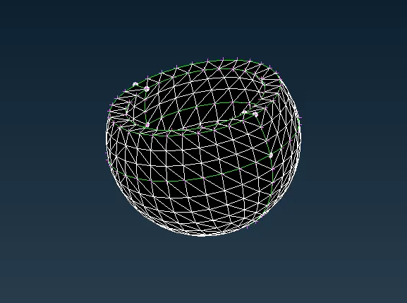
-The component must be meshed using Mesh Generation > Spot Mesh.
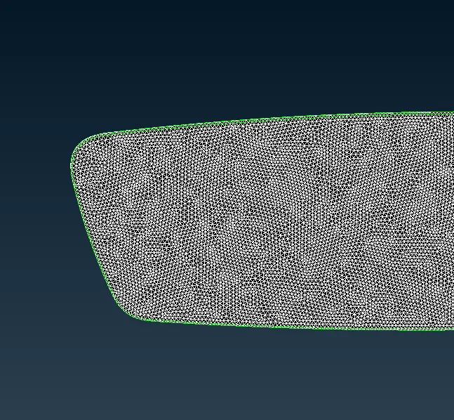
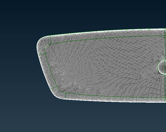
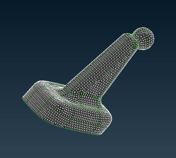
-Curved Areas and fillets must be captured perfectly using Ortho-Tria elements (Structured) whereas Flat surfaces can be meshed using Tria elements (Unstructured).
-This interchange in elements depending on the curvature of the faces is done to reduce computational time.
The images below include the 4 meshed parts of the component:
4. VOLUME MESH:
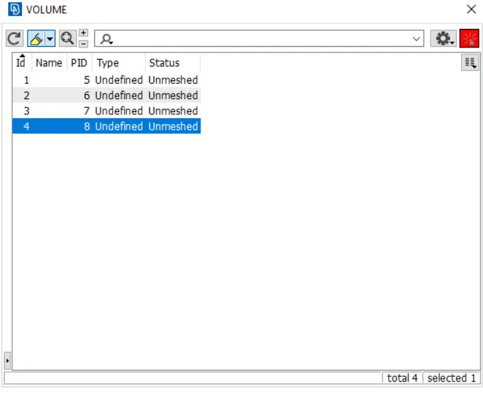
- To create a volume mesh from the initially created Shell mesh, check the Volumes > List in the Volume Mesh Module which will have no defined volumes.
- In-order to define a volume, go to Volumes > Define > Manual, and select the region to that comprise of a particular volume.
- PID selection tool is used to select the volume and there must be 4 volumes in the list as they are separate entities as shown below:
- The Type includes Defining of the Mesh type such as Tetra FEM, Tetra Rapid and in-order to mesh each volume, right click over each volume and click Remesh. You will receive an
option to choose the type of the mesh. On selection, a volume mesh will be generated for the component.
- Repeat the same process for all the 4 volumes.
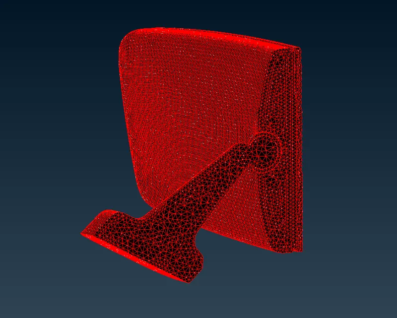
Fig-11: Volume mesh generated
FINAL MODEL-
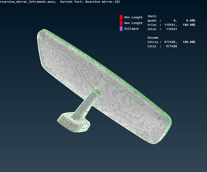
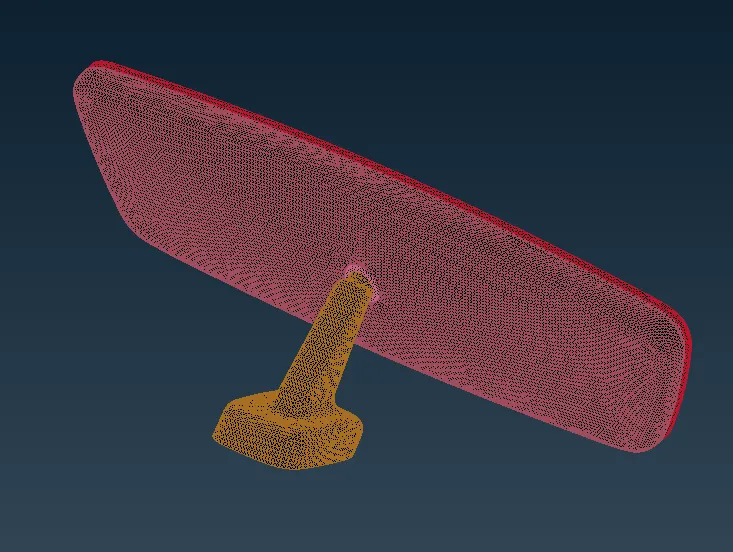
Fig-12: No off-elements Fig-13: Geometry turned off for model
LEARNING OUTCOMES -
1. Gained knowledge regarding tools required to perform solid meshing
2. Learned to create PID and and assign volumes for closed shell elements
3. Familiarized with ortho-tria and tria mesh tools and also gained knowledge in eliminating tet collapse, min length and max length errors.
CONCLUSION -
The geometry clean-up of the component was performed initially and shell meshed as per the given Quality criteria which was converted to a Solid mesh. Good mesh flow was achieved and Quality criteria was satisfied by zero off-elements.