Week 3 - 2D meshing for sheet metal
WEEK 3 CHALLENGE:
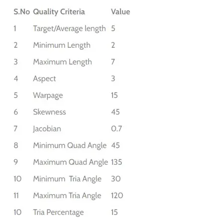
Aim – To generate a mixed mesh on the hood model using pre-processing software (ANSA) using the following parameters to evaluate the Quality criteria.
Objective –
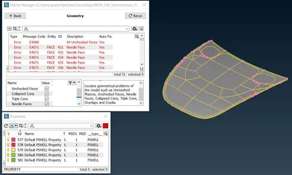
- Perform a Geometry check for the model to find any unchecked faces after importing the CAD file.
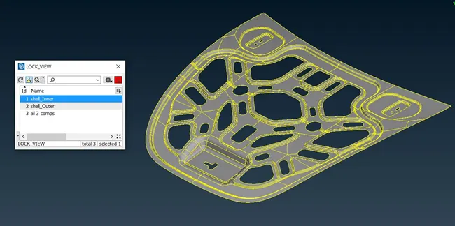
- Lock all components in different views to analyse each component separately.
- Extract Mid-surface using Offset option and Feature Area option to select all surfaces automatically.
- Set PID for all the Mid-surfaces generated and assign thickness to the components.
- Re-define construction lines in certain areas to capture the features.
- Define values for Quality criteria and Mesh parameters.
- Mesh the surfaces of the components using Best mesh method.
Procedure –
1. Geometry Check
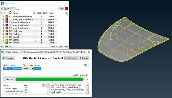
Tools > Checks >Geometry option is used to view any Unchecked faces in the CAD Geometry. The following Errors need to be fixed manually or by using Auto-fix to proceed further with the process.
- Before Geometry Clean-up:
- After Geometry Clean-up:
2. Manage Locked Components:
The Hood Geometry consists of 5 different components that need to meshed separately, so that requires the user to view each of them separately by using Focus >! NOT, OR, AND options.
3. Mid-surface Extraction:
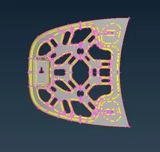
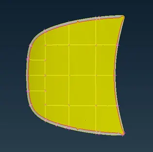
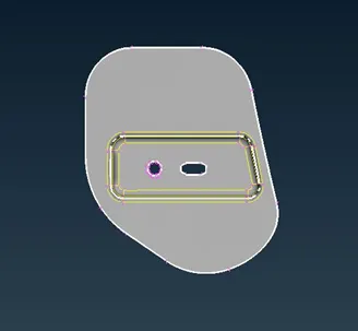
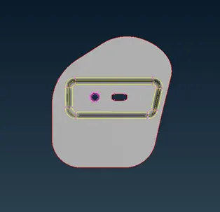
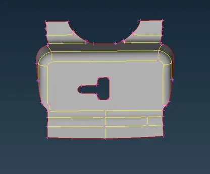
Topo > Faces > Offset and along with Visibility > Feature Area option is used to select all featured surfaces at a stretch to Undergo mid-surface generation.
The following Images include the Mid-surface of all 5 components:
4. Assigning PID and Thickness:
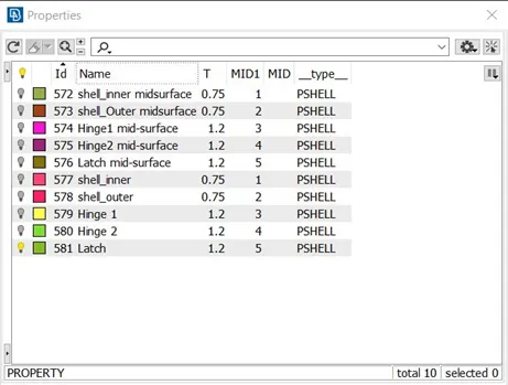
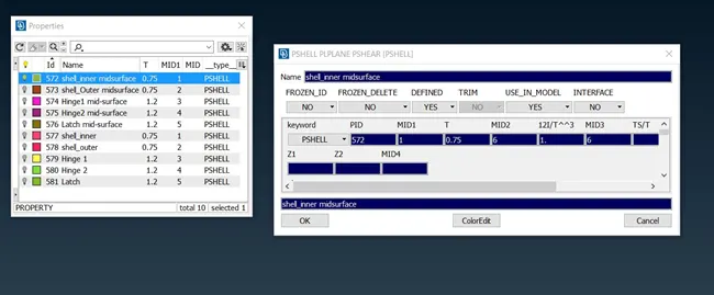
The PID or Product Identification number is used to define the thickness and material for the components.
Lists > Properties > New > PSHELL are the options used to define the PID for each of the 5 components.
5. Re-defining Construction Lines:
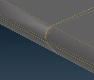
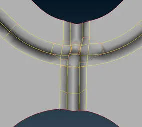
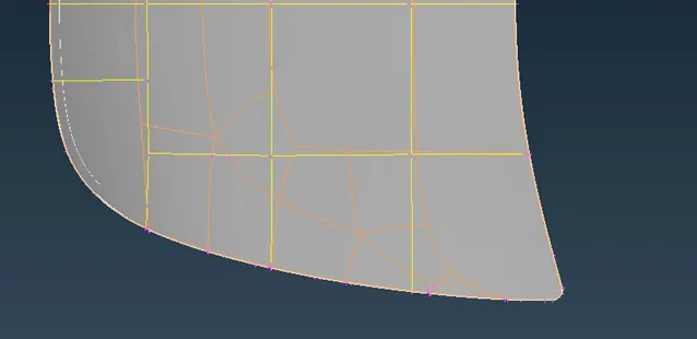
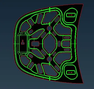
Use Macros > Join to merge constructions lines which will lead element failure and Macros > cut to define and capture the features in the geometry.
To define the Hemmed Region in the Outer hood surface, a single con is drawn in the middle while joining all other attached cons. This will give a good mesh flow in the fillet region without any distortions.
6. Quality Criteria and Mesh Parameters:
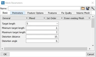
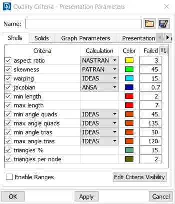
Utilities > Mesh Parameters and Quality criteria consist of User define values that can vary according to the requirement or application of the component.
The following are the values defined for the Hood geometry:
7. Meshing:
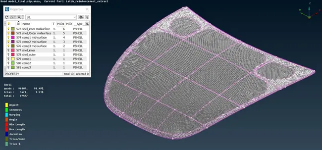
Mesh generation > Best > Select is used to generate the best automated mesh results by ANSA. All 5 components are meshed in a similar manner and then the mesh is refined to match the elements to the above given Quality criteria parameters and the percentage of triangular elements is reduced manually by using commands such as Split, Swap, Paste, Smooth and Reconstruct.
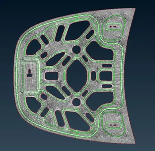
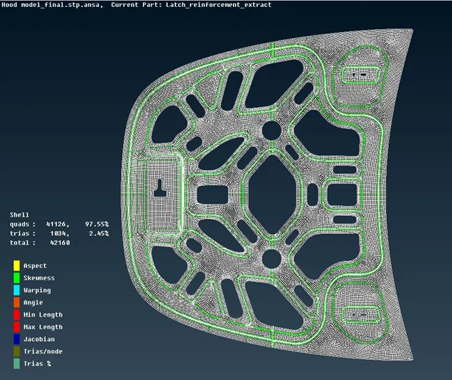
COMPLETED MESH MODEL:
Learning Outcomes:
- Familiarisation of ANSA User Interface
- Resolving geometric errors for pre-processing
- Procedure for extracting mid-surface.
- Performing Topology to avoid distortion of the featured surfaces.
- Method of mesh generation to meet Quality criteria and good mesh flow.
Conclusion :
Successfully generated Mesh with good flow with all elements meeting the above stated Quality criteria with tria % of 1.51 for the entire component.