Week- 5 - Solid meshing
Aim
To check for the geometrical errors, mesh the surfaces with the given 2D element Quality criterias and use tetra elements to mesh the volumes defined in the model and check for the quality after volume meshing for the given Rear view mirror component.
Procedure
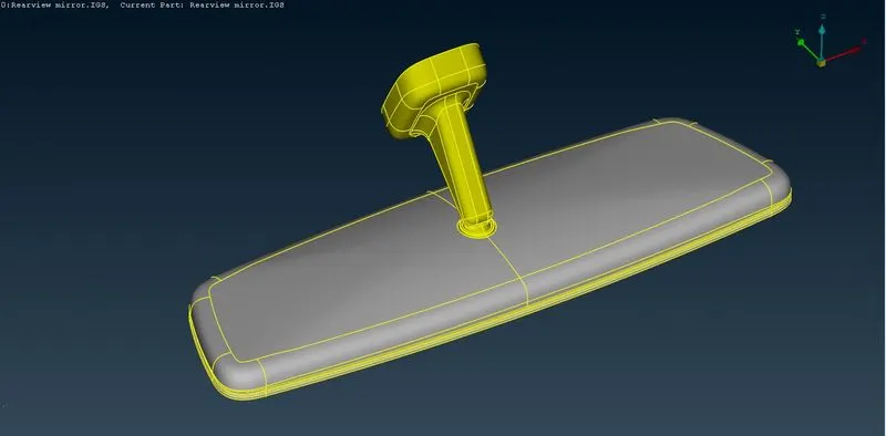
Imported the CAD geometry using the open option on ANSA. As ANSA supports the .igs, .stp, .stl files hence the challenge .stp file is successfully opened.
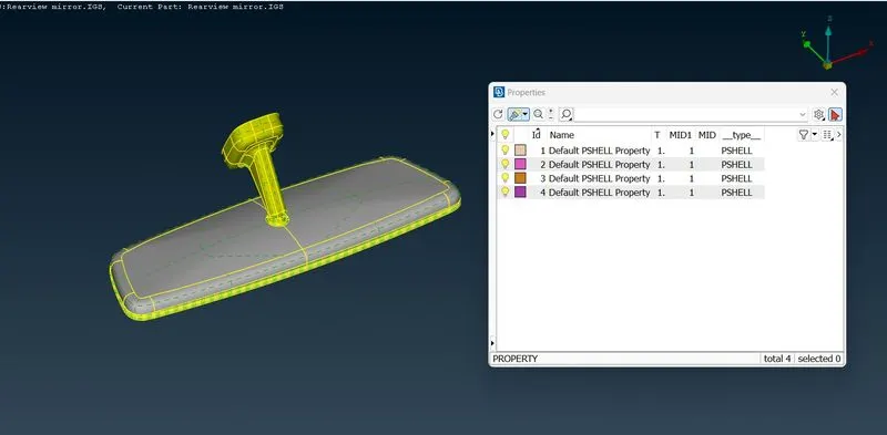
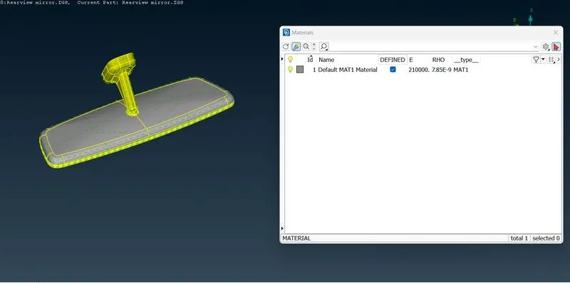
Checked the property ids and defined the material for the rear view mirror by going to the material tab and ticking the define tickbox.
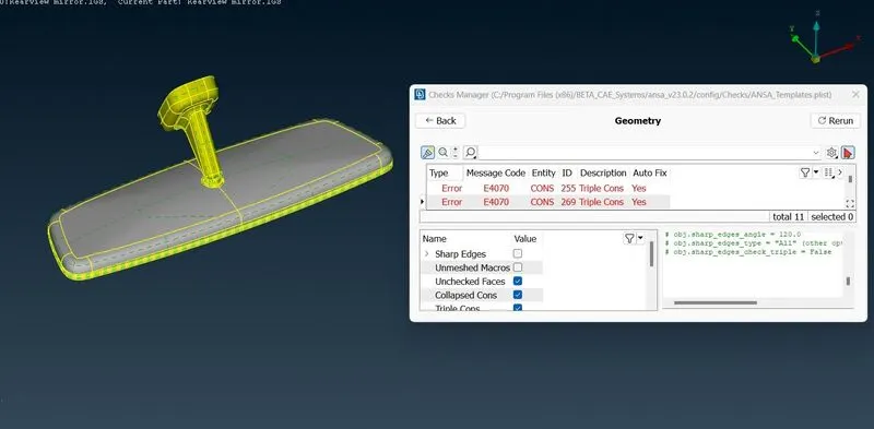
Geometry checkup for the whole component is performed using checks > geometry > execute and errors are generated. Then selected all the errors and performed auto fix on them and fixed them and lastly again executed the checks geometry for any further errors. Hence in this way geometry cleanup is done.
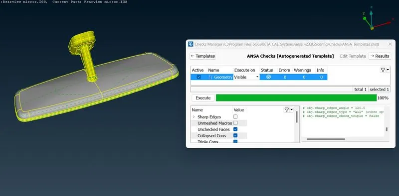
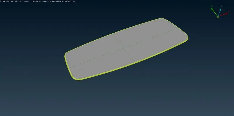
Here no midsurface is required as volume mesh has been carried out. The parts have to be 2D meshed first then the volume mesh will be carried out. The parts which have to be meshed here are as under:
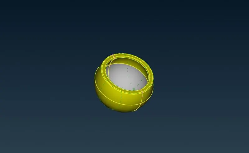
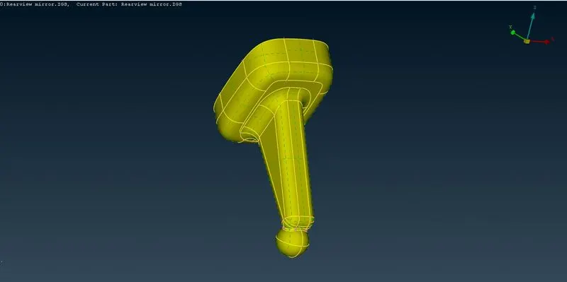
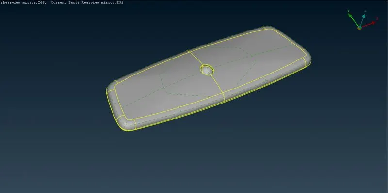
Now quality criteria for 2D mesh is given in the question only which is as under:
|
S.No |
Quality Criteria |
Value |
|
1 |
Target/Average length |
1 |
|
2 |
Minimum Length |
0.5 |
|
3 |
Maximum Length |
2 |
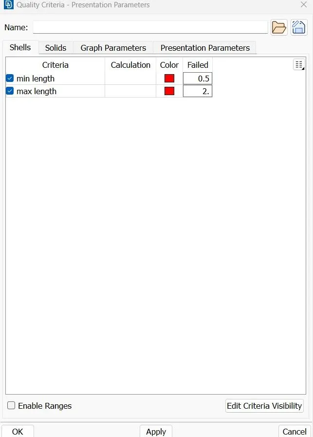
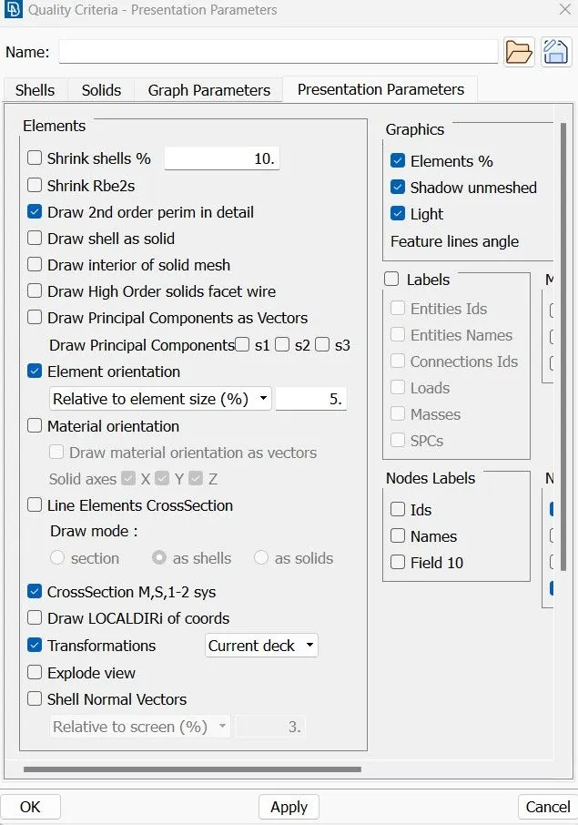
Now quality criteria is provided for quality checks so that the component is devoid of quality issues so that boundary conditions and loads can be applied further. Using the F11 key opened the quality criteria table and ticked the required quality parameters and provided the above mentioned values, hid the inactive parameters and clicked on apply. Then went to the presentation parameters and ticked the Elements% and under detail & demand effect slides the cursor and selected all details. Then pressed apply an ok to make those changes.
Then provided the mesh parameters such as Target length and Min length. Changed the element type as tria as in the challenge the volume meshing has to be done using only the tetra elements.
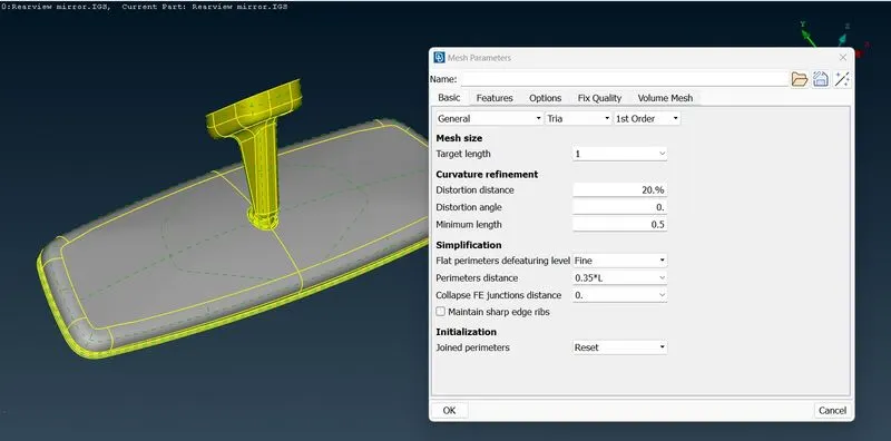
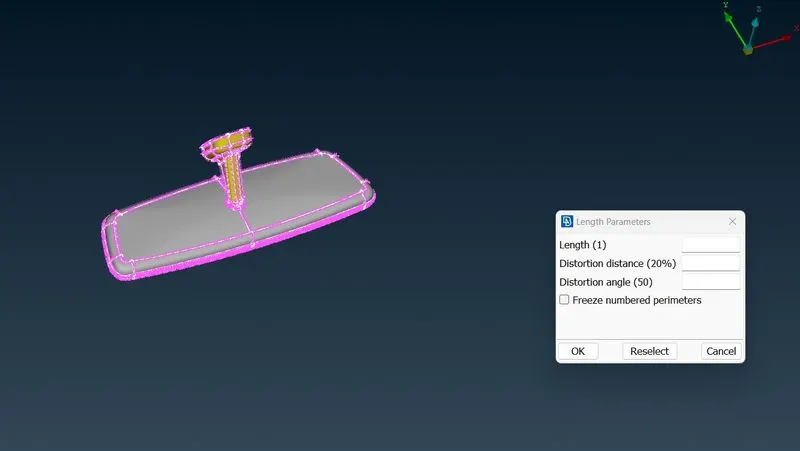
As all the quality parameters are given, we can go for meshing so switching to MESH deck. All the elemental perimeter length should be equal to or nearby the Target Length hence used the Length option to redesignate the element to element distance.(MESH Deck>Perimeter>Length>Selected the whole component>Middle Click>Provided the target length>ok). After the operation, manually checked the node distance whether the change has been applied or not. Also checked for the number of edges for the holes and found odd then changed edge number using the Number option to give the nearer even no(MESH Deck>Perimeter>Number>Selected the whole component>Middle Click>Provided the required no of edges>ok).
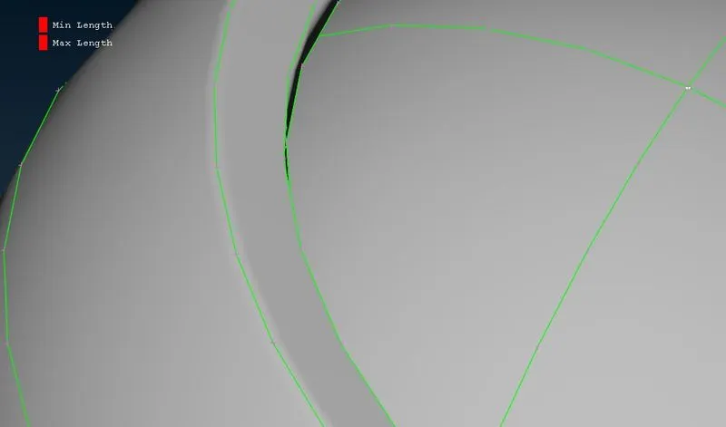
Now before going to mesh the components are defeatured by removing unnecessary surfaces, edges, otherwise bad mesh will be generated and also may face quality issues for node distance as well which is present here in this case. Here the Cut option is used to join and create new surfaces as it can perform both the operations with left and right mouse click respectively. Especially the filets are to be defeatured to meet the quality(MESH Deck>Macros>Cut>Left click/Right click). Also used curve>middle and projected the middle curve on the maxima of the bead and curve structures, removed the cuts adjacent to perform defeaturing.
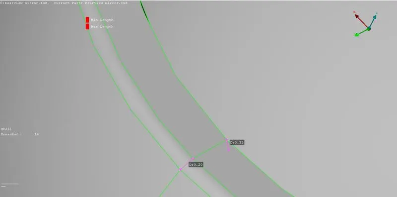
becomes
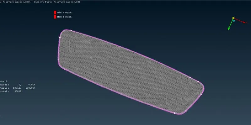
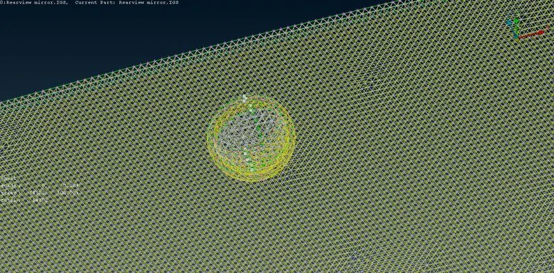
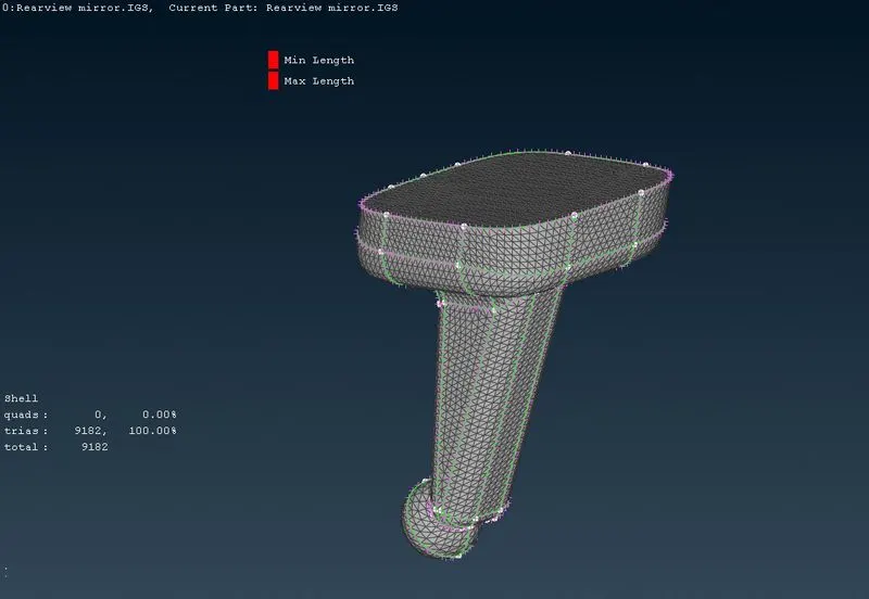
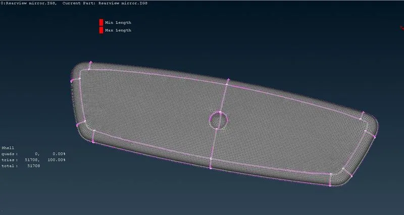
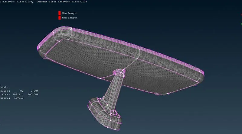
Now meshed the part using the SPOT MESH (MESH Deck>Mesh generation>SPOT MESH>Select>Select the parts to Mesh>Middle Click) as it will let us choose the type of element to mesh a particular area. Here ortho tria is used for curved surfaces and tria for the flat surfaces, but in some places ortho tria is used on flat surfaces also as it gave better mesh pattern. Then turned on the hidden mode to see the quality criteria and the elements which are failing to meet quality. Then Reconstruct(MESH Deck>Shell Mesh>Select the elements>Middle Click x3), Smooth(MESH Deck>Shell Mesh>Select the elements>Middle Click x3) and Improve to reconstruct, smoothen and improve the mesh flow and to reduce quality issues.
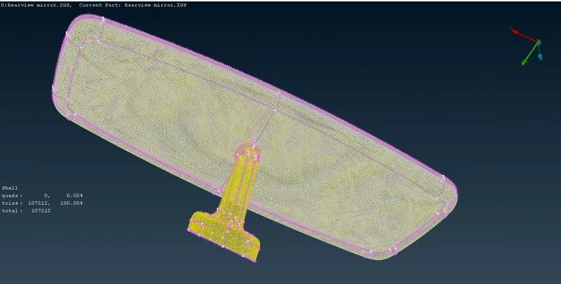
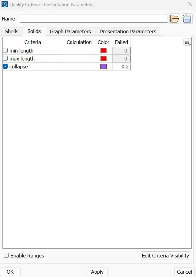
Now solid quality criteria is given which is as under:
|
S.No |
Quality Criteria |
Value |
|
1 |
Tet collapse |
0.2 |
Here if the height of the tetra element is less than the optimum height then the element will fail for Tet collapse.
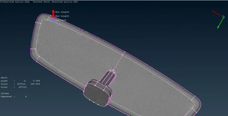
Now, the below image shows that volume is unmeshed.
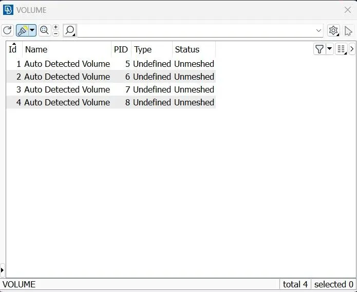
Now switched to the VOLUME MESH deck. There defined the volume for the component(VOLUME MESH deck>Volume>Define). Now under the list option the unmeshed volumes are seen.
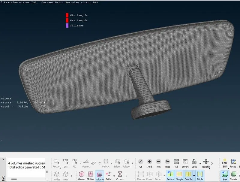
Now meshed the volumes using the unstructured mesh algorithm Tetra Rapid(VOLUME MESH deck>Unstructured Mesh>Tetra Rapid) as it only gives tetra elements on meshing, otherwise Tetra FEM is also used, but it gives both tetra and pyramidal elements.
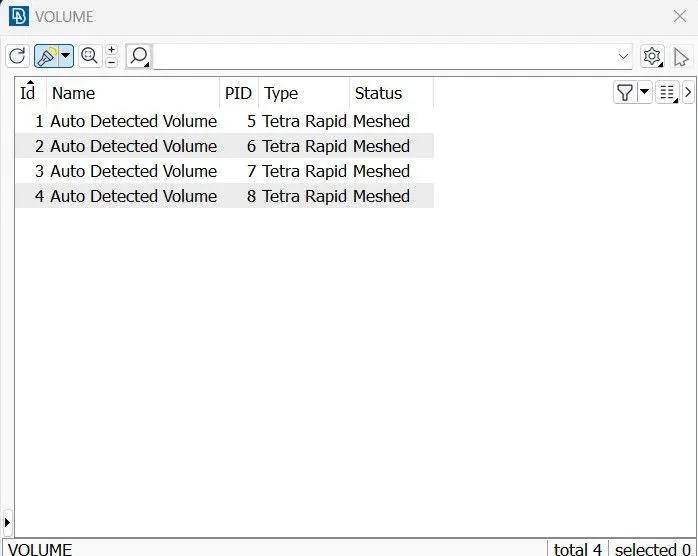
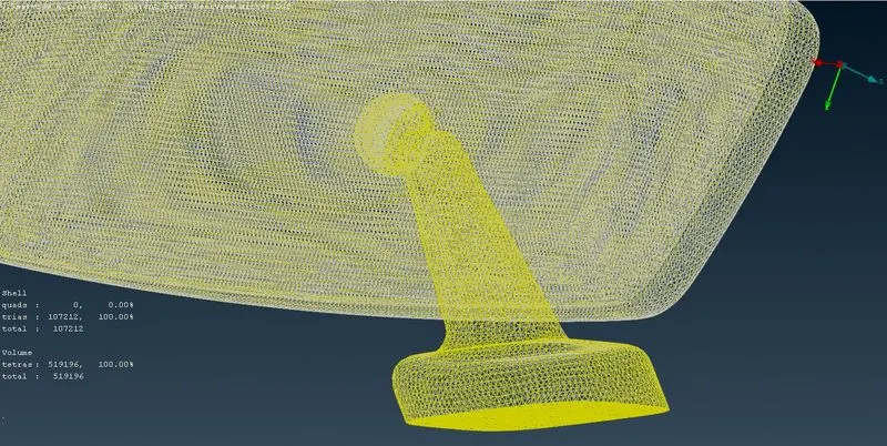
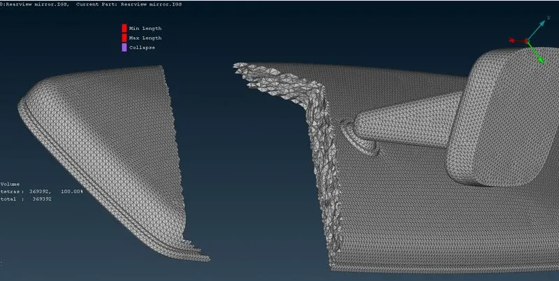
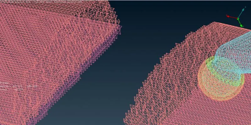
After meshing both the shell and volume elements tab is visible and there it can be seen that te shell mesh elements are many times less than the volume meshed elements and it is due to the presence of growth rate not in the surface but in the bulk.
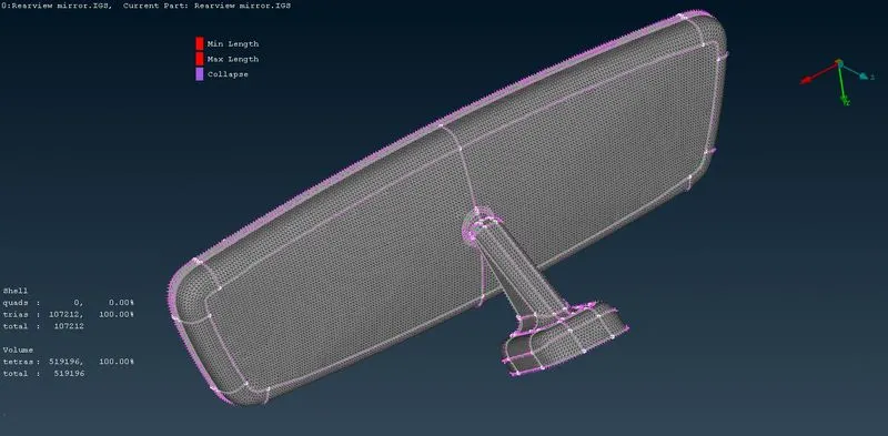
When hidden mode is off:
When geometry and FEA is off:
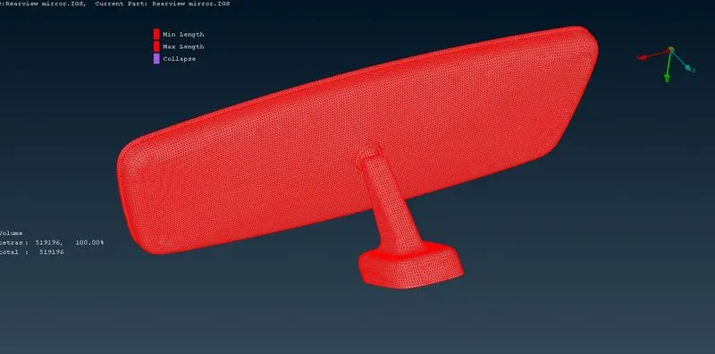
When perimeter is off and bounds is on:
Now the elements can be released by using Volume>Release or we can export it as it is.
Learning Outcomes
At the end of this challenge I am more familiar with volume mesh deck, can perform topology cleanup, can perform defeaturing, can improve the mesh and resolve quality issues.
Conclusion
Hence the geometry cleanup, shell and volume meshing with quality checks has been successfully done.