Week 6 - Creating connection for Rear door
Aim
To create and apply different PIDs for different components and to perform suitable connections, for the given Rear door FE model.
Procedure
Imported the CAD geometry using the open option on ANSA. As ANSA supports the .igs, .stp, .stl files hence the challenge .stp file is successfully opened. As th FE model is given upfront hence the connections are needed to be performed.
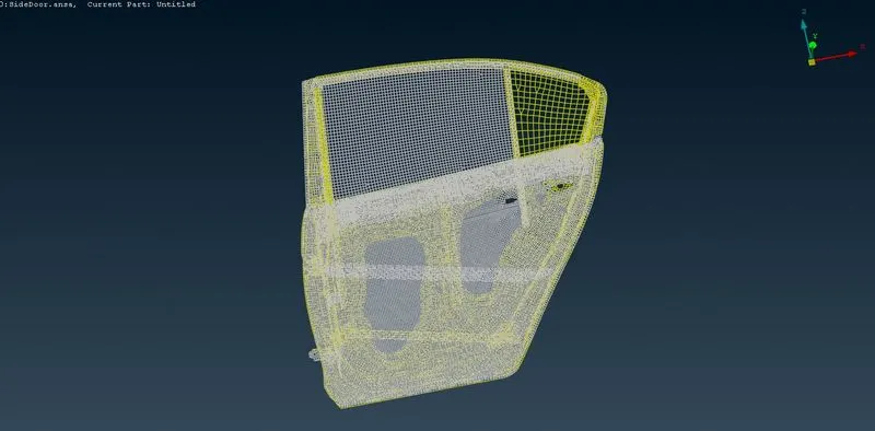
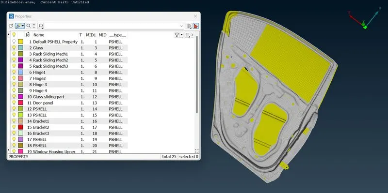
The component is assigned to a single PID only. Hence assigning the PIDs using SetPID for the sub parts which will help in the connections as in some places 4 parts are required to make a connections. At that time if there is only single PID the sometimes 'connection failed' error message comes which will not an issue here.
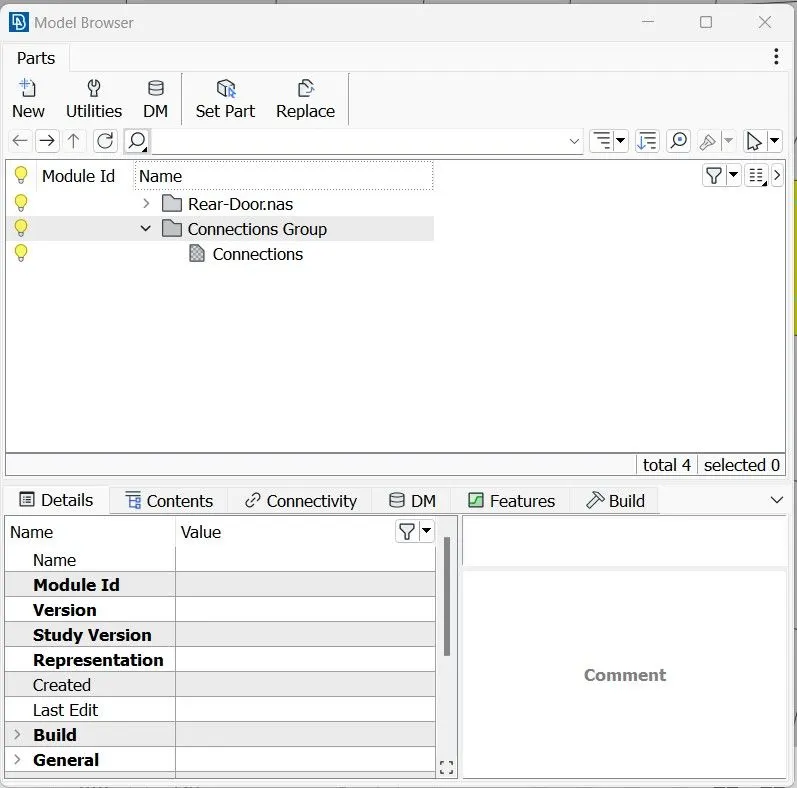
Under the Model Browser Connection group and part is created to visualize the connections independenly.
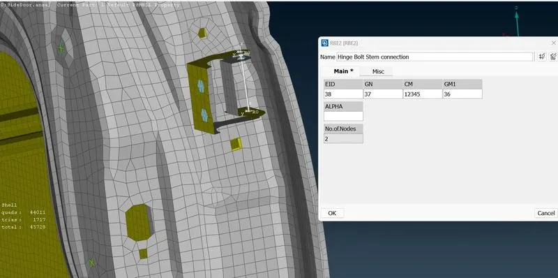
Now approached the NASTRAN Deck to carry out the connections as for NVH analysis NASTRAN deck is used. Under ELEMENTS tab used RBE2 many nodes for defining rigid connections in the holes and bolt connections. Also used the 2 node RBE2 to define the bolt stem connections. Particularly in the hinge area changed the connection element's DOF from 123456 to 12345 in order to allow motion in the rotational z axis, otherwise the door will be constrained along the rotational z-axis hence the door will not open. Used ELEMENTS>INFO to change the DOF.
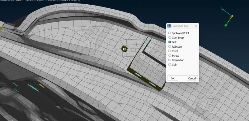
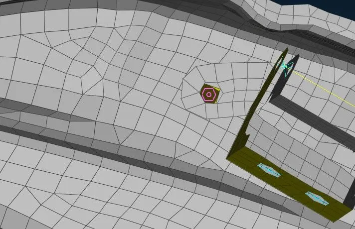
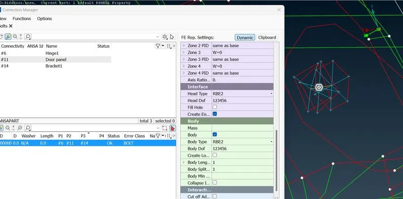
Also carried ou the bolt connection by converting 3D point at COG to a Bolt and then using connection manager with FE Rep type as Bolt. Also the for node capturing In/Out as zone is given to capture the washer limit.
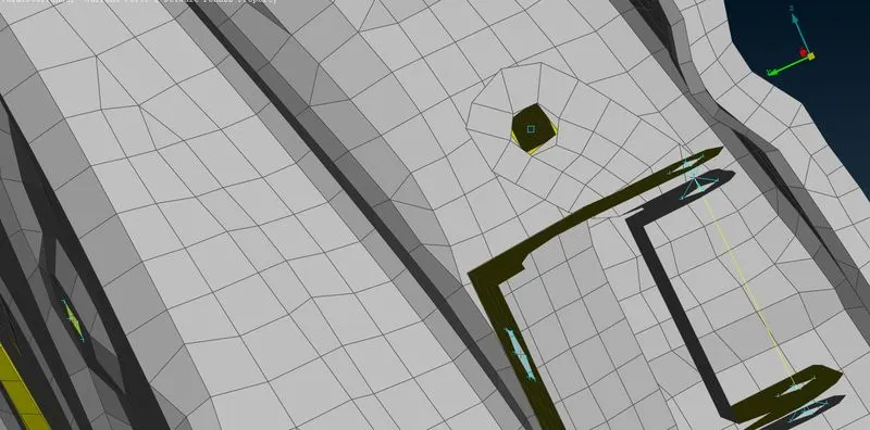
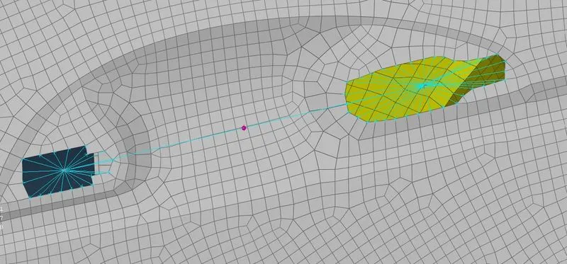
For the door handle, many nodes RBE2 connections are made and then mass of 0.0001 ton was given at the COM of the connection using CONMass(CONMi>CONM2>Nodes). Hence a purple dot is generated specifying the centre of mass.
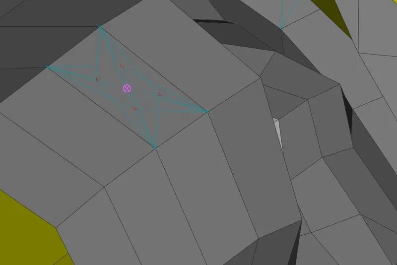
Then Carried out the spot weld connections wherever required following the same procedure as bolt but here the 3D point is converted into Spotweld Point instead of Bolt. Here in the connection manager the for FE rep type RBE3-HEXA-RBE3 to perform spot weld. The RBE3 pinflags is converted from 123/123456 to 123456/123456.
Now for the weather strips CBUSH connections are used as it will be used for both damping and isolation of inner environment from outer environment purpose.
As the CAD is not given hence using Feat2Curve from Classic Mesh module to generated curves of the window glasses, both sliding and fixed for the Spotweld line which will generate the CBUSH connections in the window glass lane.
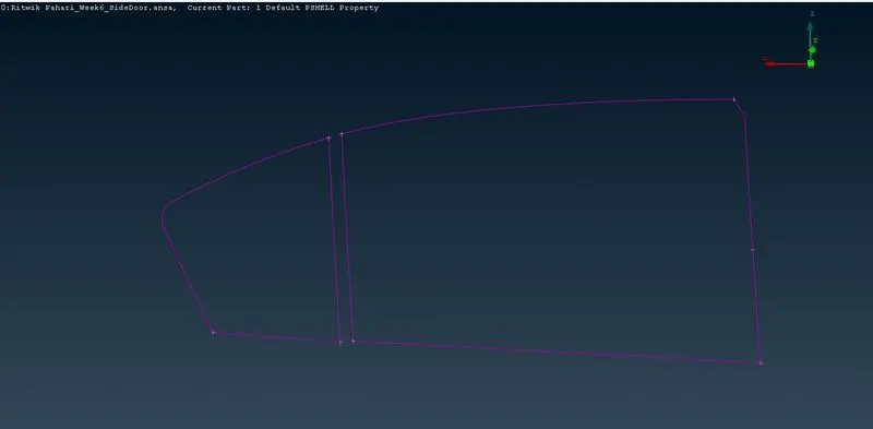
Then converted the curves one by one to Spotweld Line.
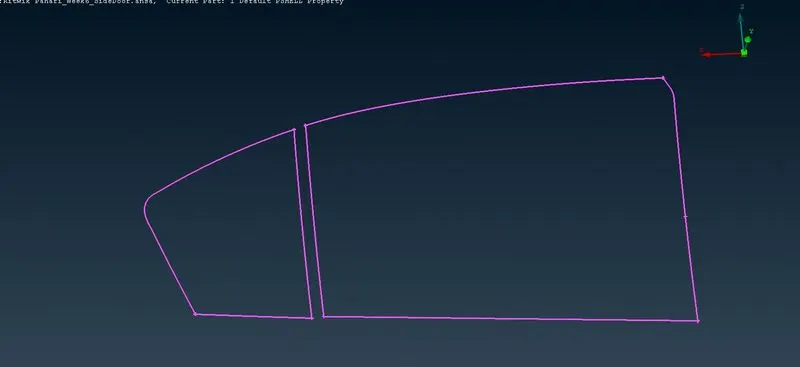
Then used the connection manager to generate the CBUSH elements. Under the FE rep type this time RBE3-CBUSH-RBE3 is used with ticking the keep all branches option. After the generation of the CBUSH elements it was seen that though the connection is made the orientation of the elements are differering from each other as they are following local coordinate system. This can give bad simulation results. Now all the elements can be oriented according to the global coordinate system but there are huge no. of CBUSH elements, hence cannot be oriented manually. It is done by provoding a modification to all the CBUSH elements with modification rules as 'orient with cord' and CID(coordinate ID) as 0. This facilitates the change at once. And under the PBUSH property the 6 stiffness values are given.
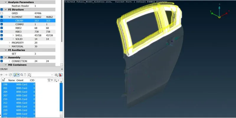
Now we can see that the CBUSH elements are oriented according to the global coordinate system.
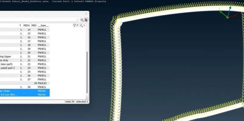
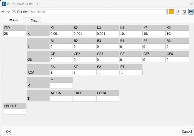
While only viewing the connections:
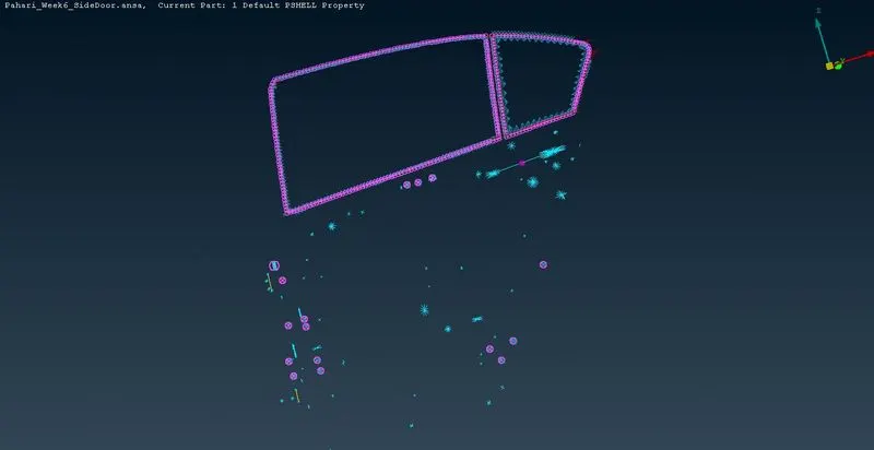
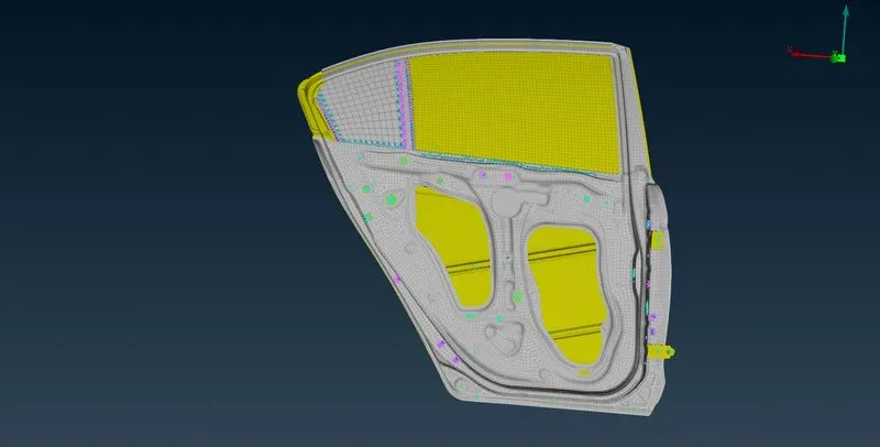
While viewing the component with all the connections:
Learning Outcomes
Learned how to create and apply PIDs for the different subparts, how to perform RBE2, spotweld, bolt and BUSH connections.
Conclusion
Hence different PIDs for different components are created and applied and suitable connections, for the given Rear door FE model has been performed.