Week- 5 - Solid meshing
Question:
For the given Rear view mirror component, check for the geometrical errors and mesh the Surfaces with the given 2D element Quality criterias given below.
|
S.No |
Quality Criteria |
Value |
|
1 |
Target/Average length |
1 |
|
2 |
Minimum Length |
0.5 |
|
3 |
Maximum Length |
2 |
Use tetra elements to mesh the Volumes defined in the model and check for the below quality after Volume meshing.
|
S.No |
Quality Criteria |
Value |
|
1 |
Tet collapse |
0.2 |
Solution:
Introduction:
Mesh generation is the practice of converting the given set of points into a consistent polygonal model that generates vertices, edges and faces that only meet at shared edges. It can have almost any shape in any size. Each cell of the mesh represents an individual solution, which when combined, results in a solution for the entire mesh.
Mesh is formed of facets which are connected to each other topologically. The topology is created using following entities:
Mesh is formed of facets which are connected to each other topologically. The topology is created using following entities:
- Facet - A triangle connecting three data points
- Edge - A line connecting two data points
- Vertex - A data point
Types of meshing:
Meshes are commonly classified into two divisions, Surface mesh and Solid mesh. Let us go through each section one by one.
A]
Surface mesh: A surface mesh is a representation of each individual surface constituting a volume mesh. It consists of faces (triangles) and vertices. Depending on the pre-processing software package, feature curves may be included as well.
Generally, a surface mesh should not have free edges and the edges should not be shared by two triangles.
The surface should ideally contain the following qualities of triangle faces:
Generally, a surface mesh should not have free edges and the edges should not be shared by two triangles.
The surface should ideally contain the following qualities of triangle faces:
- Equilateral sized triangles
- No sharp angles/surface folds etc. within the triangle proximity sphere
- Gradual variation in triangle size from one to the next
The surface mesh generation process should be considered carefully. It has a direct influence on the quality of the resulting volume mesh and the effort it takes to get to this step.
B]
Solid Mesh: Solid mesh, also known as volume mesh, is a polygonal representation of the interior volume of an object. There are three different types of meshing models that can be used to generate a volume mesh from a well prepared surface mesh.
Solid Mesh: Solid mesh, also known as volume mesh, is a polygonal representation of the interior volume of an object. There are three different types of meshing models that can be used to generate a volume mesh from a well prepared surface mesh.
The three types of meshing models are as follows:
- Tetrahedral - tetrahedral cell shape based core mesh
- Polyhedral - polyhedral cell shape based core mesh
- Trimmed - trimmed hexahedral cell shape based core mesh
Once the volume mesh has been built, it can be checked for errors and exported to other packages if desired.
Meshes can be classified into two divisions from the grid perspective, namely Structured and Unstructured mesh. Let us have a look at each of these types.
Structured Mesh:
Structured meshes are meshes which exhibits a well-known pattern in which the cells are arranged. As the cells are in a particular order, the topology of such mesh is regular. Such meshes enable easy identification of neighboring cells and points, because of their formation and structure. Structured meshes are applied over rectangular, elliptical, spherical coordinate systems, thus forming a regular grid. Structured meshes are often used in CFD.
Unstructured Mesh:
Unstructured meshes, as the name suggests, are more general and can randomly form any geometry shape. Unlike structured meshes, the connectivity pattern is not fixed hence unstructured meshes do not follow a uniform pattern. However, unstructured meshes are more flexible. Unstructured meshes are generally used in complex mechanical engineering projects.
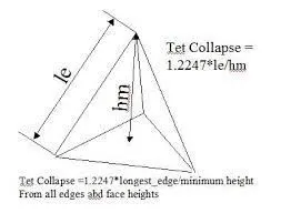
Tet collapse is one of the quality parameters, which will be checked while generating Tetrahedral elements. It can be calculated by measuring the distance of a node from the opposite face, then each of the four values will be divided by the Square root of the opposite face's area.
3D meshing of the Rear view mirror:
Now let's see solid (3D) meshing of the Rear view mirror.
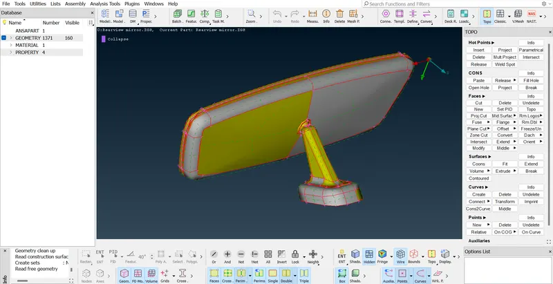
Fig1.1: Provided 3D model of the Rear view mirror for the solid meshing.
We will mesh this component using the Tetra elements. Tetra mesh can be created by using the regular tria elements and the ortho tria elements.
We generally use the ortho trias on curve surfaces to capture the feature precisely whereas regular trias are used to capture flat surfaces. Since the solving time taken by the ortho trias is more than that of the regular trias we must take this into the consideration while developing the mesh.
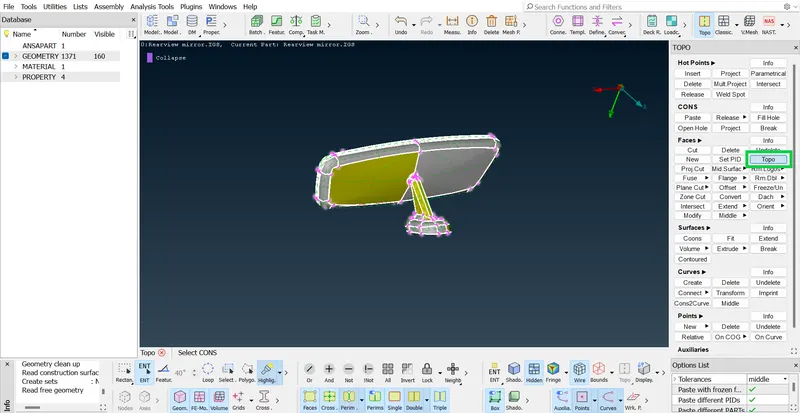
Fig1.2: Executing the 'Topo' command to join the disassembled surfaces to get the 3D closed model.
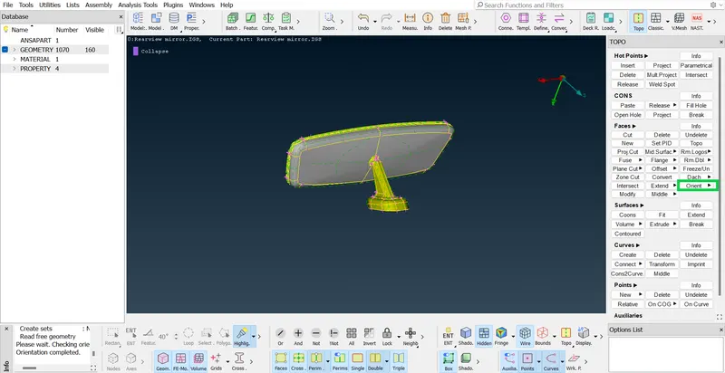
Fig1.3: Executing the 'Orientation' command to get the optimized orientation of the 3D closed model.
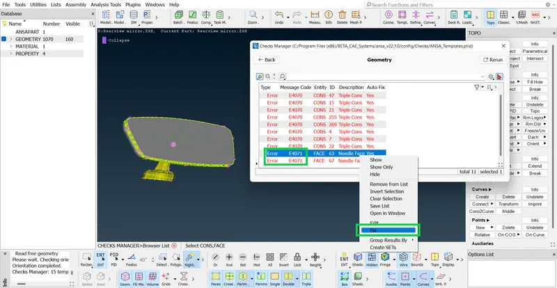
Fig1.4: Executing the 'Geometric check' command to get the 3D closed model for meshing without issues.
Here the Triple cons cannot be fixed, since it is a 3D model consisting of features for which triple cons are necessary. But we can fix the needle surfaces from the list.
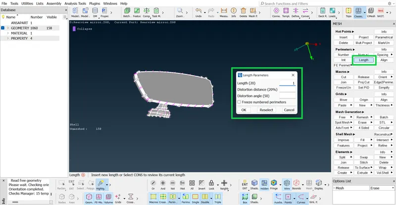
Fig1.5: Executing the 'Length (perimeters and Micros)' command to prepare the model for meshing as per specified element length.
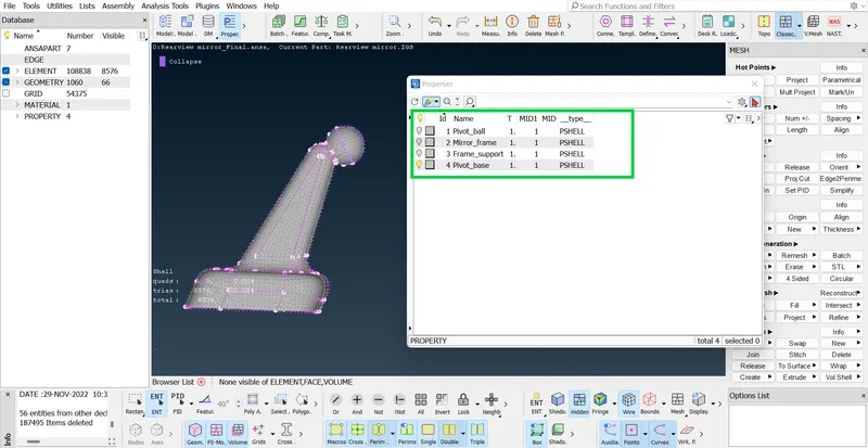
Fig1.6: Checking and Renaming the properties of the 3D model to check the number of components available for meshing.
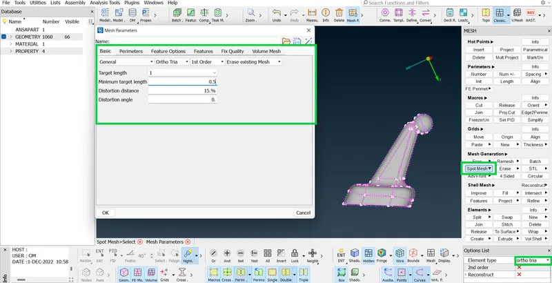
Fig1.7: Setting up the meshing parameters as per the requirement of the model.
We created the 2D (Shell mesh) for the component visible by using the 'Spot mesh' command using the 'Ortho trias'
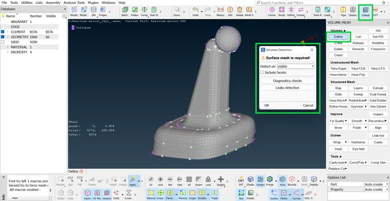
Fig1.8: Defining the volume for the visible component with 2D shell mesh using 'Define' command.
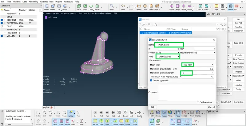
Fig1.9: Editing the defined volume and setting up the 3D volume mesh parameters for solid mesh of the visible component.
Here we must enter the value of the Maximum element length as the Target length i.e. 1.
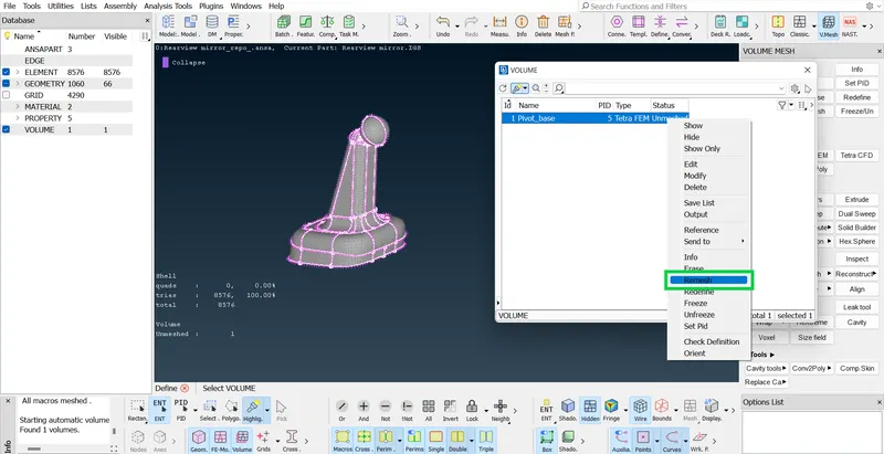
Fig1.10: Remeshing (creating solid mesh) the visible component (Volume) by using the 'tetra FEM' approach.
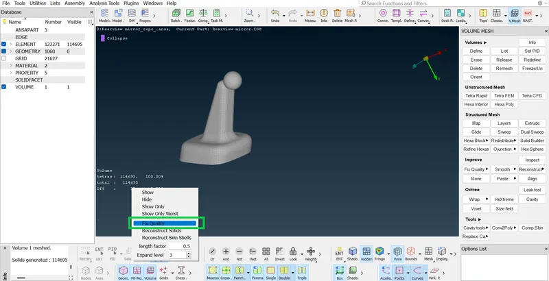
Fig1.11: Check the status bar and 'Fix quality' of the failed elements.
Here we are checking our 3D mesh for 'collasp' parameter.
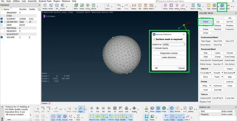
Fig1.12: Defining the volume for the visible component with 2D shell mesh using 'Define' command.
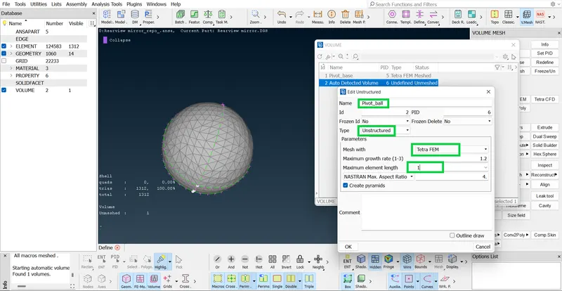
Fig1.13: Editing the defined volume and setting up the 3D volume mesh parameters for solid mesh of the visible component.
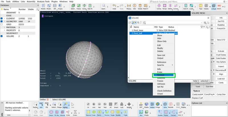
Fig1.14: Remeshing (creating solid mesh) the visible component (Volume) by using the 'tetra FEM' approach.
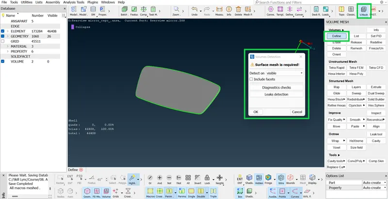
Fig1.15: Defining the volume for the visible component with 2D shell mesh using 'Define' command.
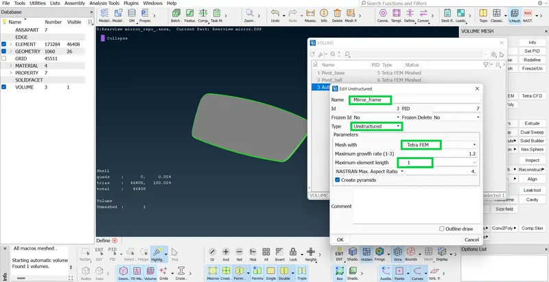
Fig1.16: Editing the defined volume and setting up the 3D volume mesh parameters for solid mesh of the visible component.
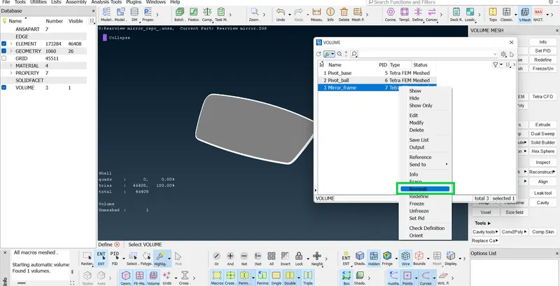
Fig1.17: Remeshing (creating solid mesh) the visible component (Volume) by using the 'tetra FEM' approach.
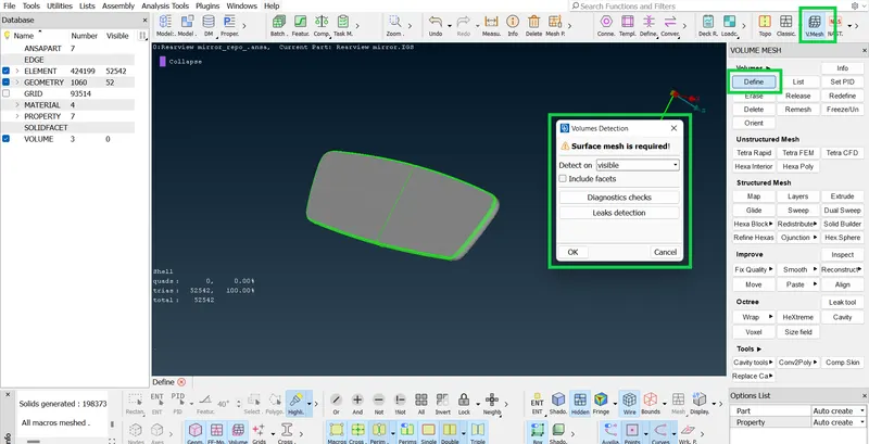
Fig1.18: Defining the volume for the visible component with 2D shell mesh using 'Define' command.
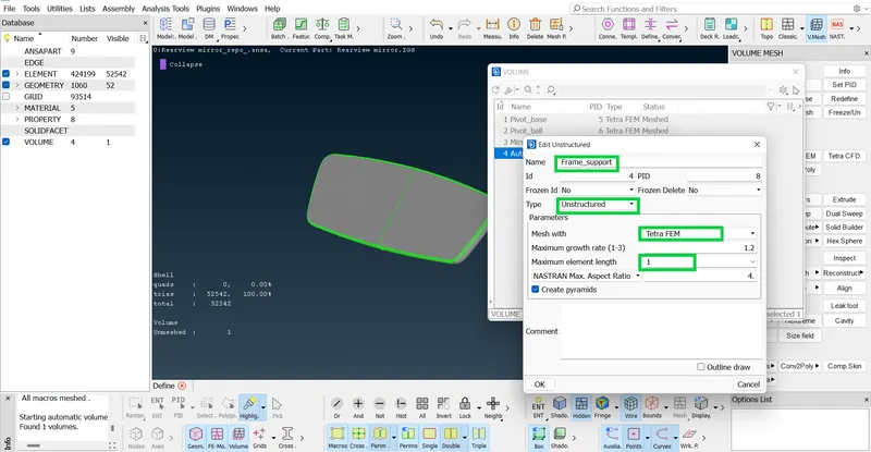
Fig1.19: Editing the defined volume and setting up the 3D volume mesh parameters for solid mesh of the visible component.
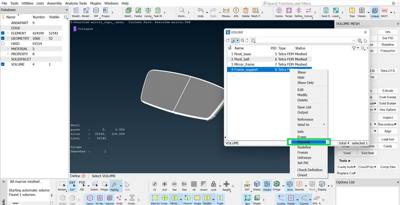
Fig1.20: Remeshing (creating solid mesh) the visible component (Volume) by using the 'tetra FEM' approach.
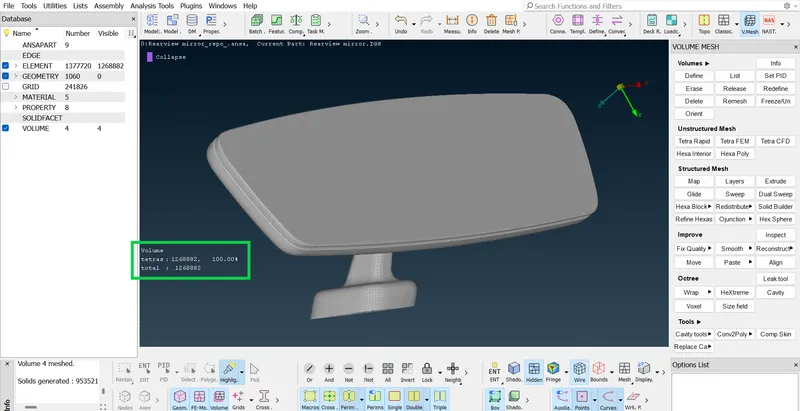
Fig1.21: Final 3D solid mesh for the Rearview mirror assembly with zero failed elements.
Learning outcomes:
- We learnt and practiced, How to create 3D solid mesh for the given component.
- To obtain the best mesh possible with minimum solving duration with optimized results.
- To model the given component as per the quality requirements and standards of the industry.
Conclusion:
We studied and practiced the 3D solid meshing of automotive component with proper mesh flow, as per the quality requirements of the automotive components.