Week- 5 - Solid meshing
Aim :-
To Create Solid Mesh for the given Rear View mirror with the given element quality criteria and assign volume by Tetra FEA.
Methodology :-
- Geometry Clean-up
- Spot Meshing on 3D model.
- Solid Shell Definition.
- Tetra FEA
Quality Criteria :-
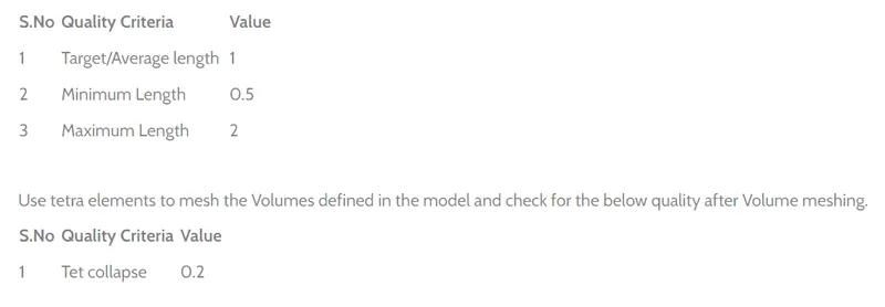
Procedure :-
CAD before Topo & geometry clean-up,
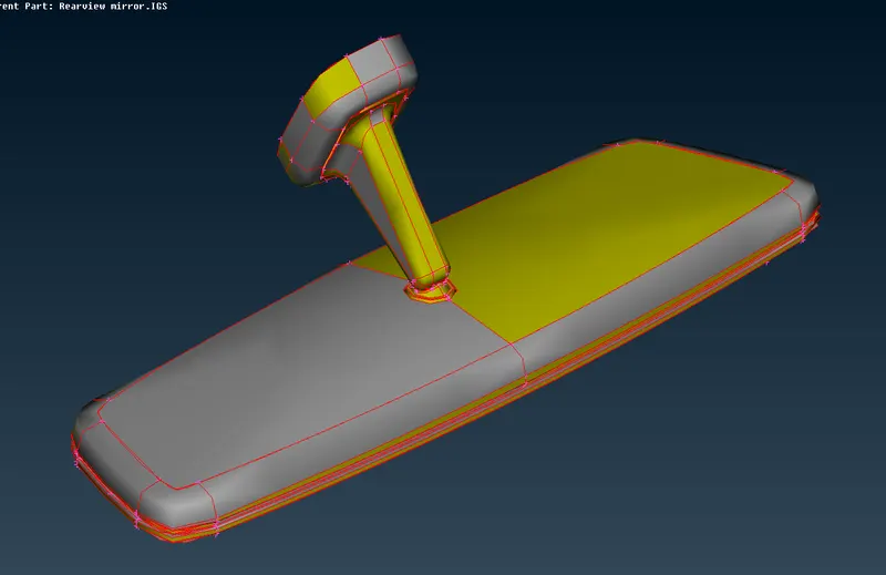
Fig : 1
1. Geometry clean-up:
Check CAD topologies using checks manager, check parameters such as triple con, single con, Share Edges, etc.
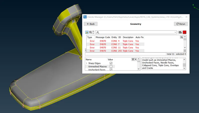
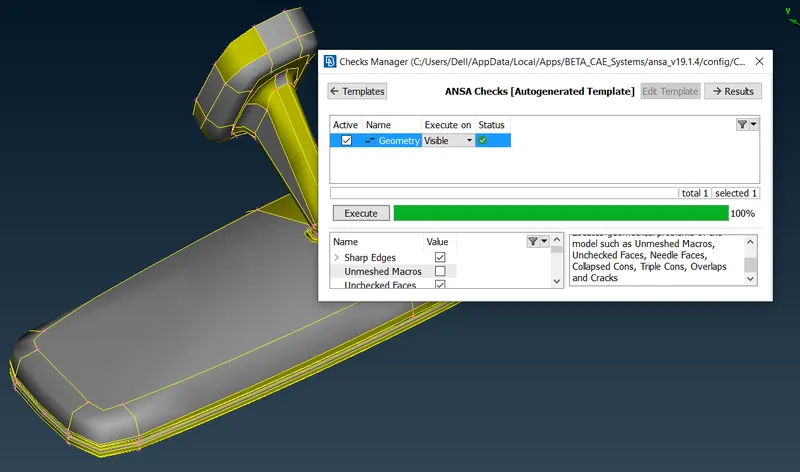
Fig : 2.1 Fig : 2.2
2. Clean up the CAD model using Topology module and remove the inconsistence in entities.
3. Switch on to entity mode, isolate each part & check for errors with the help of Boolean operations.
4. Define material as given in the statement or standard material will be steel as default.
5. If there are any errors in geometry, auto-fix whichever is possible. Errors which cannot be auto fixed, right click on the error & select show only. The actual error will be displayed which has to be fixed. Similarly perform check geometry until the result passes completely.
6. Assign mesh parameters like minimum, maximum & avarage target length. Select type of mesh as Ortho Tria.
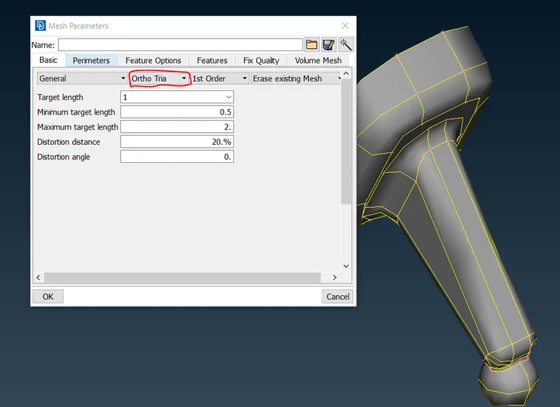
Fig : 3
7. Assign quality criteria for 2D shell as well as for the solid mesh as per the requirement.
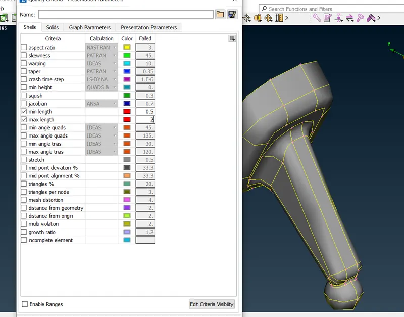
Fig : 4
8. Select Spot Mesh with element type Ortho Trias for curved features (Shown in Fig 5.1) and Trias for Flat face features (Shown in Fig 5.2).
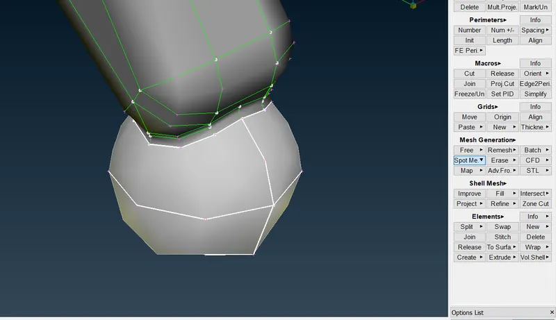
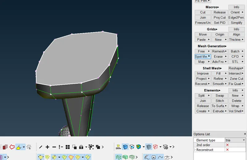
Fig : 5.1 Fig : 5.2
Similarly perform meshing completely (Shown in Fig : 6).
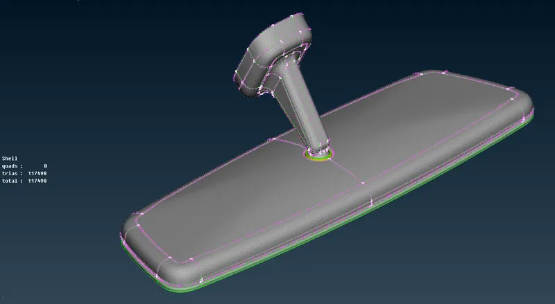
Fig : 6
9. After spot meshing is completed, move to Volume mesh module. Define solid shell by Define -> Manual -> Select the model -> OK
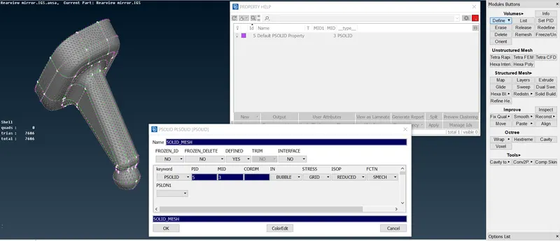
Fig : 7
Assign Solid property for all the components in the model.
10. Unstructure the mesh using Tetra FEA in Volume Mesh module.
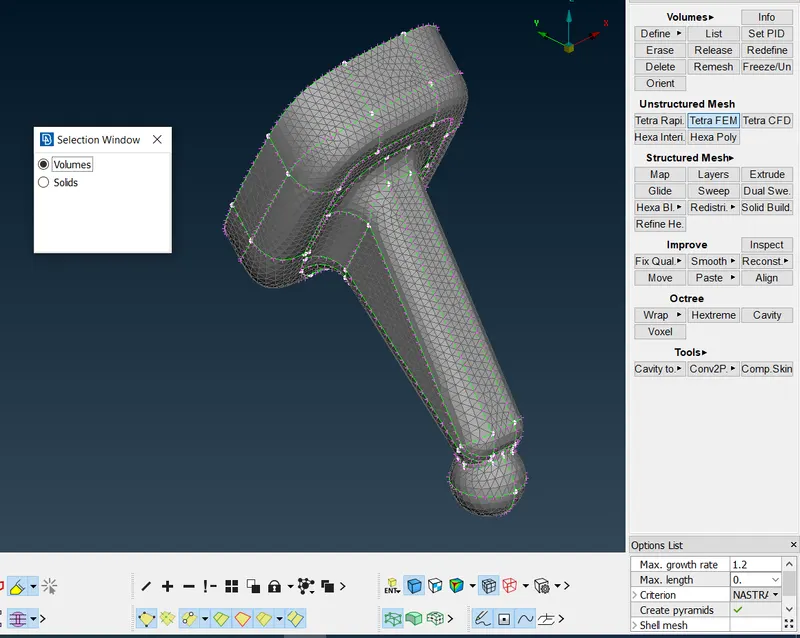
Fig : 8.1
Similarly perform for all the components (SHown in Fig 8.2).
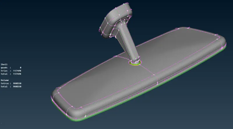
Fig : 8.2
11. Section the model as shown below to check the tetra structure.
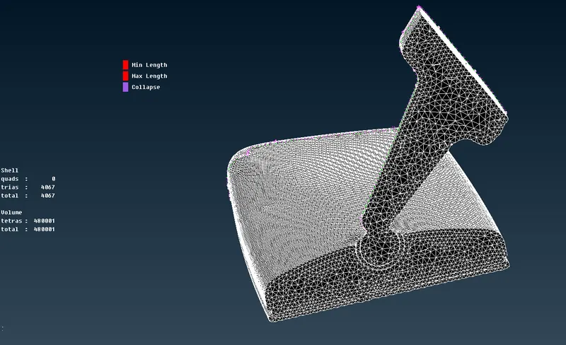
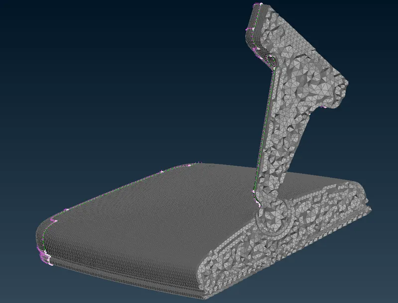
Fig : 9.1 Fig : 9.2
Learning Outcome :-
- Spot Meshing with different element types.
- Volume meshing.
- Tetra Collapse fixing.
- Unstructuring the mesh.
- Bounce view.
Conclusion :-
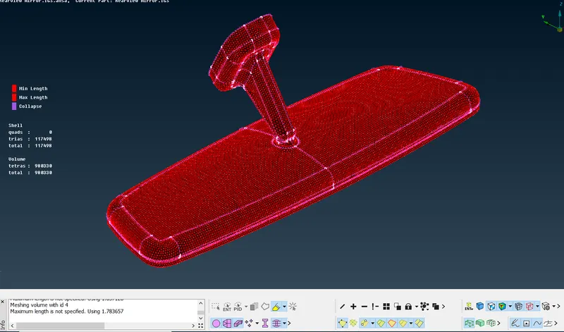
Fig : 10
The given Rearview mirror model is meshed considering to the prescribed quality criteria, each component is assigned with a separate Solid PID.
Meshing is completed with no quality issues like minimum/maximum Length and tet collapse.