Week 5:- Rest Unit & Clamp Unit Design Challenge
WEEK 5: CLAMP UNIT AND REST UNIT
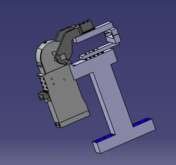
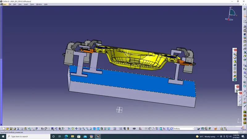
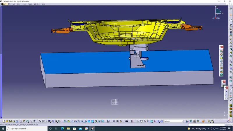
Objective: To design 3 different types of power clamp units with different riser, blade and clamp arm for the given car panel and design 2 different types of rest unit for the given car panel.
Rest Unit:
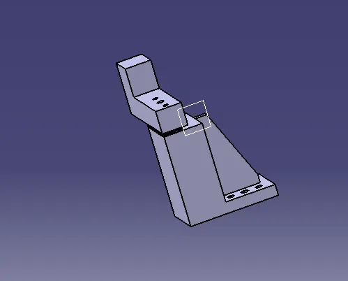
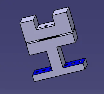
- Rest unit is a unit designed to support a car panel using Mylar/ NC block. Rest component is rested only, no upper clamp or force applied there. It is the simplest unit to design because it has fewer parts to design and the purpose is only to rest the car panel. Because of the simplicity the rest unit is combined with other units to reduce the cost of the overall project.
- It can be combined with a clamp unit to clamp as well as rest the car panel. It can be combined with a locating unit to locate as well as to rest the car panel.Also locating, clamping and rest unit can be combined together in one unit to reduce cost.
- There is no cylinder attached to it. It has a rest Myler, blade and riser and below are different parts of rest units. Rest uni is also divided into simple support unit, multiple support units and retractable support units
Clamp unit
A clamp unit is a unit designed to clamp/hold the car panel with NC blocks/ mylars/ rest by using a pneumatic cylinder. Clamp arm, finger, rest/back-up , L-Block, shims, riser, pneumatic cylinders are typical clamp units. Clamping force should be considered while designing clamp units. Usually clamp open position is 90 deg. Fingers are attached to clamp mylar. In clamp unit shim to one side is more than enough because it will restrict translation motion in upward direction and downward direction only. There is another type of clamp unit known as swivel type. There is a pivot point around which the clamp arm will rotate.
3-2-1 Principle:
A workpiece is free in space and can move in an infinite number of directions. For analysis, this motion can be broken down into 12 directional movements or degrees of freedom. All 12 degrees of freedom must be restricted to ensure proper referencing of a workpiece.
The 12 degrees of freedom all relate to the central axis of the workpiece. Notice the 6 axial degrees and 6 radial degrees of freedom. The axial degrees of freedom permit straight- line movement in both the directions along the 3 principal axes shown as X,Y,Z.
The radial degrees of freedom permit rotational movement, in both clockwise and counterclockwise radial directions around the same three axes.
The purpose of fixture is:
- Resting
- Locating
- Orienting
- Clamping.
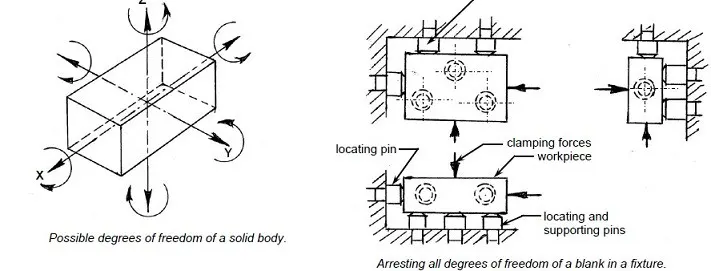
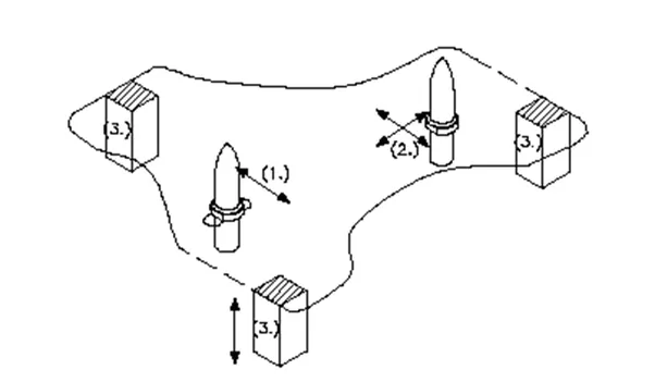
Resting: In a fixture the workpiece should rest in such a way that it doesn't move or vibrate on the resting blocks.
Locating: The fixture should locate the workpiece such that all the operations to be performed on it are performed without any problem and all of them are performed effectively.
Orienting: The fixture should orient the workpiece such that all the operations to be performed on it are within the reach of the workpiece.
Clamping: A clamp is a fastening device used to hold or secure objects tightly together to prevent movement or separation through the application of inward pressure. There are many types of clamps available for many different purposes.
Clamping Guidelines: Locating the workpiece is the first basic function of a jig or fixture. Once located, the workpiece must also be held to prevent movement during the operational cycle. The process of holding the position of the workpiece are clamps. To perform properly, both the clamping devices and their location on the work holder must be carefully selected.
Factors in selecting clamps:
Clamps serve two primary functions
They must hold the workpiece against its locators.
The clamps must prevent movement of the workpiece.
Procedure of clamping the workpiece to the panel:
Place the workpiece, supply air at clamp side without installing clamping block, operate the clamp arm to the end of clamp.
Under the above conditions, adjust the shim so that the space between the work piece and the clamping block is about 0.5mm. Theoretically there is no clapping force for holding a workpiece under this condition.
In order to generate clamping force from the state described in step B, insert additional shim. The thickness of the shim differs depending on the arm length and pressure, so please refer to the graph on front matter as a guide. About 10% error may occur due to the difference in tolerance of the clamp cylinder body.
Clamping force: Clamping force is the force required to hold a part against the locators. Clamping prevents the part from shifting or being pulled from jig or fixture during the machining operation. The type and amount of holding force needed to hold a part is usually determined by the tool forces working on the part and how the part is positioned in the tool.Sometimes the operation being performed is a factor. Clamping pressure as a general rule should only be enough to hold the part against the locators. The locators should resist the bulk of the thrust. If a part must be clamped with great deal of pressure, the tool should be redesigned so that the tool thrust is directed at the locators and the locators and tool body. Clamps must never be expected to hold all of the tool thrust.
Relation between shim thickness and clamping force:
- When a shim that exceeds the clamping force peak plotted on the graph is inserted, the self-locking mechanism doesn't work. Insert a shim with appropriate thickness. Arm length L indicates the distance between the clamp arm shaft and clamping position.
- For distance A between knock positioning pinhole and clamp arm shaft.
Considerations to be taken while designing a rest unit or clamp unit:
Considerations to be taken while designing a rest unit or a clamp unit are:
Study of process planning document:
Process document should contain following information which are necessary to design clamp unit.
- Number of sheet metal panels to be welded.
- Total number of spots.
- Welding gun details if it is already recommended by process engineers, study it in details like shape and its type.
- Study the PLP(Principle location points) data along with the nearby spot data.
Height selection:
Take an overview of the working height if we have manual welding. For robotic welding also it's important to see the working height in consideration of the robotic gun, turn table height if manual loading is done.
Gun placement:
Put the proper gun at the spot location. Do the proper gun study and place the gun as per the Geo or re-spot decision and operator approach. Once the basic gun is placed considering the throat depth and gap start building the clamp and rest block at the PLP.
Panel section creation: Take a section at PLP either in clamp opening direction or normal direction. Sections should be normal to base. Panel section through X,Y and Z direction passing through PLP. SEction will help in finalizing the shape of the clamp and rest block. Most importantly used for finalization of gun shape.
Finalization of a base plate:
Consider following things before deciding on the base plate.
- Height of max and min weld spot from floor.
- No gun arm should touch the base plate.
- Operator ergonomic while accessing all the spots.
Construction of rest and clamp block:
If standard mylar has to be used then select the proper blank size as per the requirement consider 0.5mm above the panel.
Clamp cylinder selection:
Select the cylinder as per the pivot point distance from the PLP. You may choose various cylinders: 50 dia, 63 dia, 80 Dia. As per the requirement.
Clamp and rest block creation: Create clamp orrest block as per the company guidelines.
Many companies have size of the clamp block as 20*20 mm and number of mounting screws and dowels. Materials of clamp block and rest block to be decided as per the A class panel or B class. Most of the exterior panel holdin teflon material is used.
Riser: As per OEM, Tier 1 standard use the different standards mounting risers. Do not forget to add the 5mm shim.
Rough locator or position sensor mounted on clamp unit:
If you are combining a rough locator or part sensor bracket along with the clamp unit. Take necessary care means distance of the rough locator from the panel.
Clamp unit 1: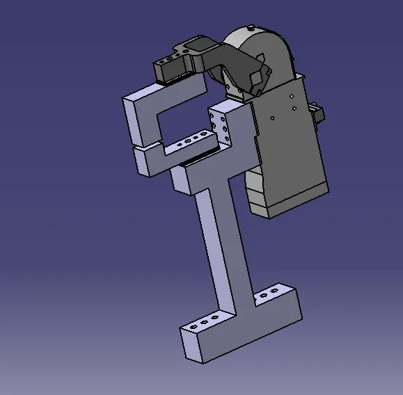
Clamp unit 2
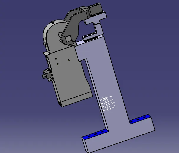
Clamp unit 3:
Clamp units supporting the panel:
Rest unit1:
Rest unit2:
Rest units supporting the panel:
Conclusion:
Hence we have designed 3 clamp units and 2 rest units.