Week 5:- Rest Unit & Clamp Unit Design Challenge
Master's Certification in BIW Fixture & Plastic Design
(Automotive BIW Fixture Design)
REPORT
Assignment-5
By Ravi Ahuja
Fixed pin Unit design:
- I started with watching tutorial videos first then I would start my designing to understand the concept and procedure followed in the designing of the fixed pin unit.
- Then I opened the car panel part file by selecting File>Open then I selected the igs file named as Then I saved the file as .CATpart format.
- Then I opened a new file in CATIA and imported the car panel part file in assembly design environment.
- I named the assembly as P001_Z01_ST010_00_00 and the following product were named as P001_Z01_ST010_01_00 and the following parts in the products were named as P001_Z01_ST010_01_01.
- Here P001 stands for First Project.
- Z01 stands for first zone.
- ST01 stands for first station.
- Then numbers after them represent the product and part numbers respectively.
- Then I created a product in the assembly environment and named it P001_Z01_ST010_01_00_FIXED_PIN_UNIT naming can also be done after the completion of project.
- Then I created a part in this product and named it P001_Z01_ST010_01_01_ Then to create a point to start at the circular hole in the panel I needed a point.
- I selected Point option from the toolbar and then selected option for circle and then I selected the hole in which I needed the pin to be designed around.
- Then after clicking OK there appeared a point on which I now have to make a plane with selecting the point and one of the plane perpendicular to the panel surface for reference.
- This can be done by selecting plane feature from the same toolbar and after getting plane we can start designing our pin.
- Now I started my sketch on the same plane by selecting the plane then sketch feature from the toolbar.
- I the selected profile option and made a sketch for pin with an axis around witch it was going to roll and extrude.
- After giving appropriate dimensions to the profile sketch I selected shaft feature and selected the sketch then clicked on ok.
- After that I would profile one side of the pin with a pocket feature and restrict the rotation of the pin.
- To place the pin in its initial position and stop it from rotation another part is used it is called pin retainer.
- Pin retainer is designed in a way that it stops the motion of the pin by obstruction and engaging the pin through the cutout.
- Then we would need a hole in a position under the pin and concentric to pin to bolt them together.
- Then I would create a new part and sketch on the pin retainer surface parallel to the car panel and make an L block and then Pad it out to create a l block to bolt pin retainer and riser together.
- Then I would create riser according the base level and bolting positions in block.
- The shapes and dimensions are not standard except some bolting holes and their clearances and threading conditions.
- The same process is repeated for the second design of the fixed pin uit with same pin but different designs for pin retainers, block and risers.
- After this we need to design the fixed pin unit for retractable pins.
- For retractable pins we used diamond shaped pins by first copying the old pin design with breaking the link and then editing it to make it diamond shaped.
- Then I imported the retractable cylinders for each design.
- Then I designed pin retainers, blocks and risers for the same.
- For the first retractable design cylinder has single pin while for the second design cylinder has double acting pin slots.
Clamp Unit design:
- I designed my first clamp unit after watching the tutorial videos and following the exact same steps.
- It included design of Clamp Mylar, Rest Mylar and riser with the imported cat-part file of clamp arm with cylinder.
- I named them with product as P001_Z03_ST010_02_00_CLAMP_UNIT and then parts were named as
- After watching the tutorials I designed 2 more clamp units with different type of risers and rest mylars.
- One of the design had “I” shaped rest mylars and clamp mylars with a blade which connects the rest mylars to the clamp arm cylinder.
- Clamp Mylar was bolted to the clamp armand moves with clamp arm.
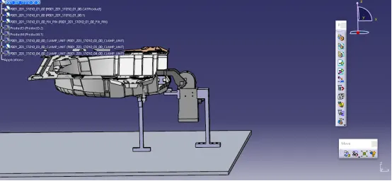
Fig. 2nd clamp unit design with I shaped Clamp mylar and a blade
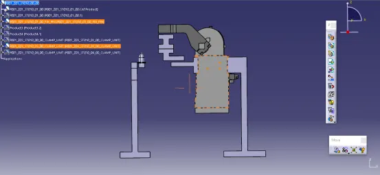
Fig. 2nd clamp unit without the panel
- Other design had a widened clamp mylar to increase the area with an I shape.
- Rest mylars are also widened and extended to the clamp arm cylinder directly to bolt the rest mylar directly to the clamp arm cylinder.
- Riser was attached on the rear side of the clamp arm cylinder.
- Riser was given a height equal to the height of the base from the point of bolting on clamp arm cylinder.
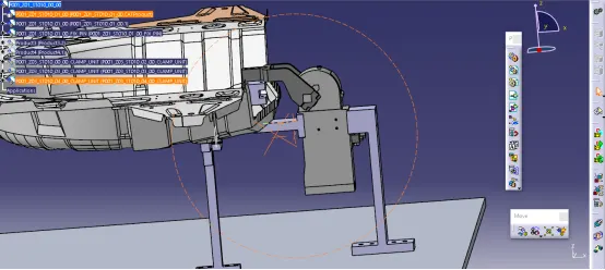
Fig. 3rd clamp unit design with widened mylars
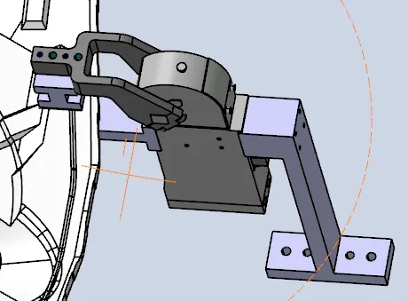
Fig. Widened Mylars for better contact