Week 5 - Rayleigh Taylor Instability
Aim:-
To conduct the Rayleigh Taylor CFD Simulation
Objective:-
- Explain different CFD models used for solving Rayleigh Taylor Instability problems
- Perform a Rayleigh Taylor instability analysis using the Volume of Fluid (VOF) multiphase model for air and water for two different mesh element sizes.
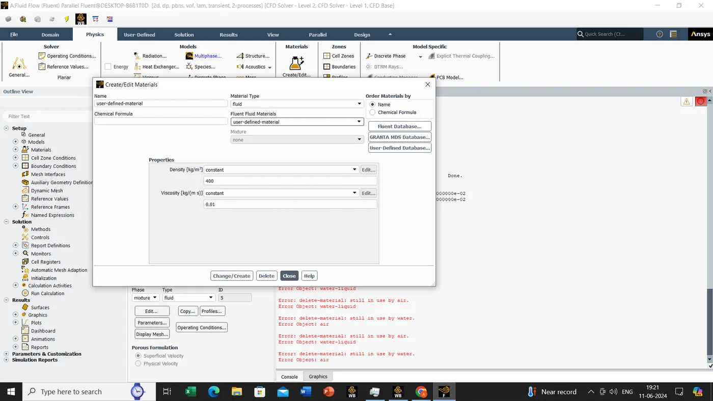
- Repeat the process for water and user-defined material with density = 400 kg/m3, viscosity = 0.001 kg/m-s, and compare the behavior
- Define the Atwood number and derive it for each case. Explain the effect of Atwood number on instability.
- So there will be total of 3 cases
- Case 1 : Mesh size- 0.5mm, Water and air
- Case 2 : Mesh size- 0.1mm, Water and air
- Case 3 : Mesh size- 0.1mm, Water and user defined fluid
Introduction:-
Rayleigh-Taylor Instability (RTI) happens when two fluids of different densities meet. The lighter fluid pushes the heavier one because of their density difference. This process aims to lower the overall potential energy of the system.
Theory:-
Initially, the system is balanced, with the heavier fluid (like water) on top of the lighter fluid (like air) in a steady gravitational field. As RTI develops, small disturbances grow, forming "plumes" that rise and "spikes" that fall. In the beginning, these disturbances grow quickly in a predictable way. Later, the disturbances become large and the process becomes more complex. The difference in densities of the fluids affects the structure of these flows.
Examples of RTI , water sitting on oil
CFD Models for Rayleigh-Taylor Waves:-
1. Mass Diffusion Model
- This model explains how mass and energy move due to viscosity, causing mixing of the fluids. Even in unstable configurations, diffusion can mix the fluids significantly if viscosity is high.
2. Single Fluid Models
->Potential Flow Model-
- This model works through all instability stages but only for a specific density ratio (Atwood number = 1). It describes bubble velocities using an ordinary differential equation.
->Buoyancy Drag Model-
- This model works for any density ratio but only in the non-linear stages. It uses equations to describe the width of the mixing layer by balancing inertia, buoyancy, and drag forces. It can't easily handle multiple mixing interfaces or 2D/3D flows.
3. Multi-Fluid Models
- These models use separate equations for each fluid and accurately model the movement of different fluid parts. They address issues like demixing (reduction of fluid mass in the mixing zone).
-> Turbulence Models
1.Two Equation K-L Model
- This model uses equations for turbulent kinetic energy (K) and turbulent length scale (L), based on the buoyancy-drag models for RT instability growth.
2.Three Equation K-L-a Model
- Adds a third equation for turbulent mass-flux velocity to the K-L model.
3.Four Equation K-L-a-b Model
- Adds a fourth equation for density-specific volume covariance, improving accuracy in reflecting changes in density fluctuations.
Atwood number
The Atwood number (A) is a dimensionless number in fluid dynamics used in the study of hydrodynamic instabilities in density stratified flows. It is a dimensionless density ratio defined as
where
ρ1= density of heavier fluid
ρ2= density of lighter fluid
Steps:-
Case 1:- Mesh size- 0.5mm, Water and air
STEP:-1
Geometry
We have to create the two square 20mmX20mm, top square is water and bottom square is AIr
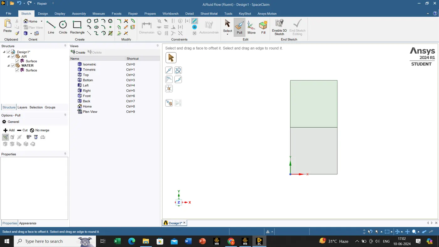
Once this process is completed we will close this tab and move on to the Mesh module/tab. since its important to check whether the share topology is share or not, supposed if we will not share topology then it wouldn't show the result in ANSYS fluent.
Step:-2
Meshing
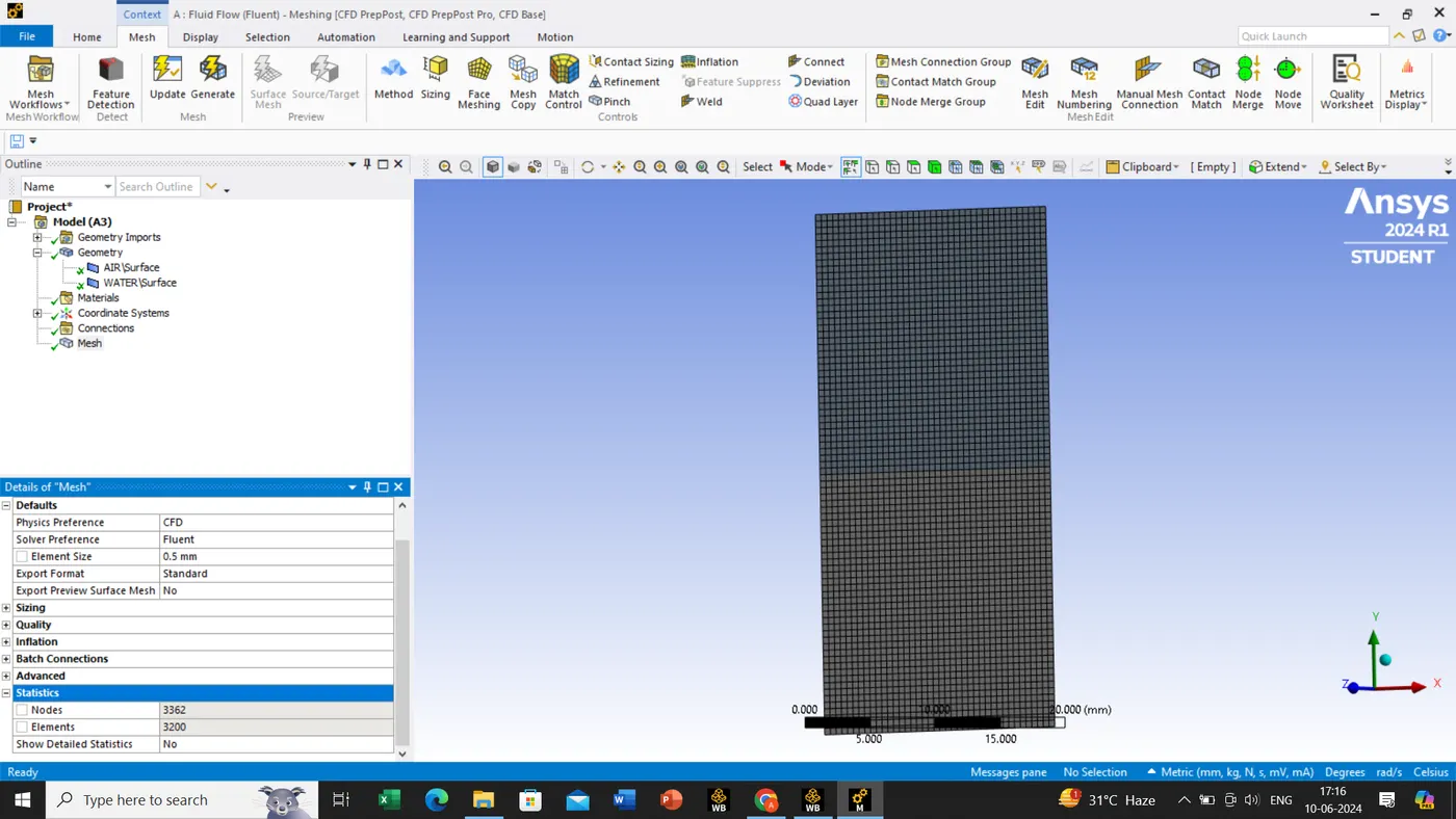
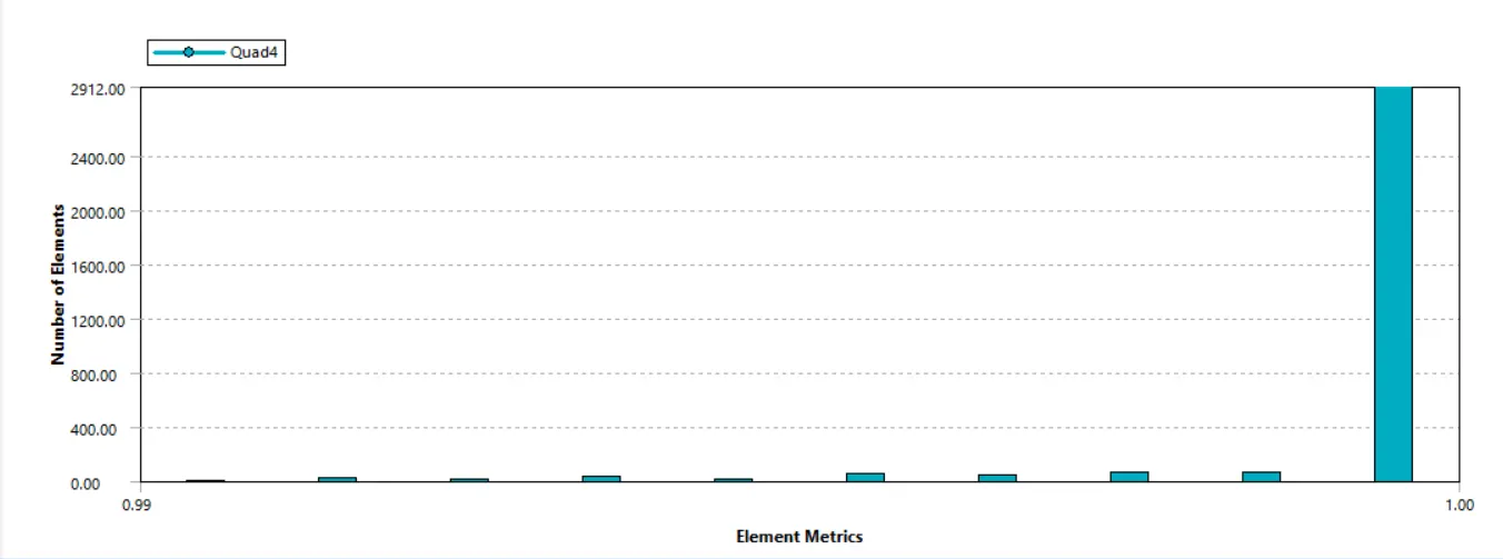
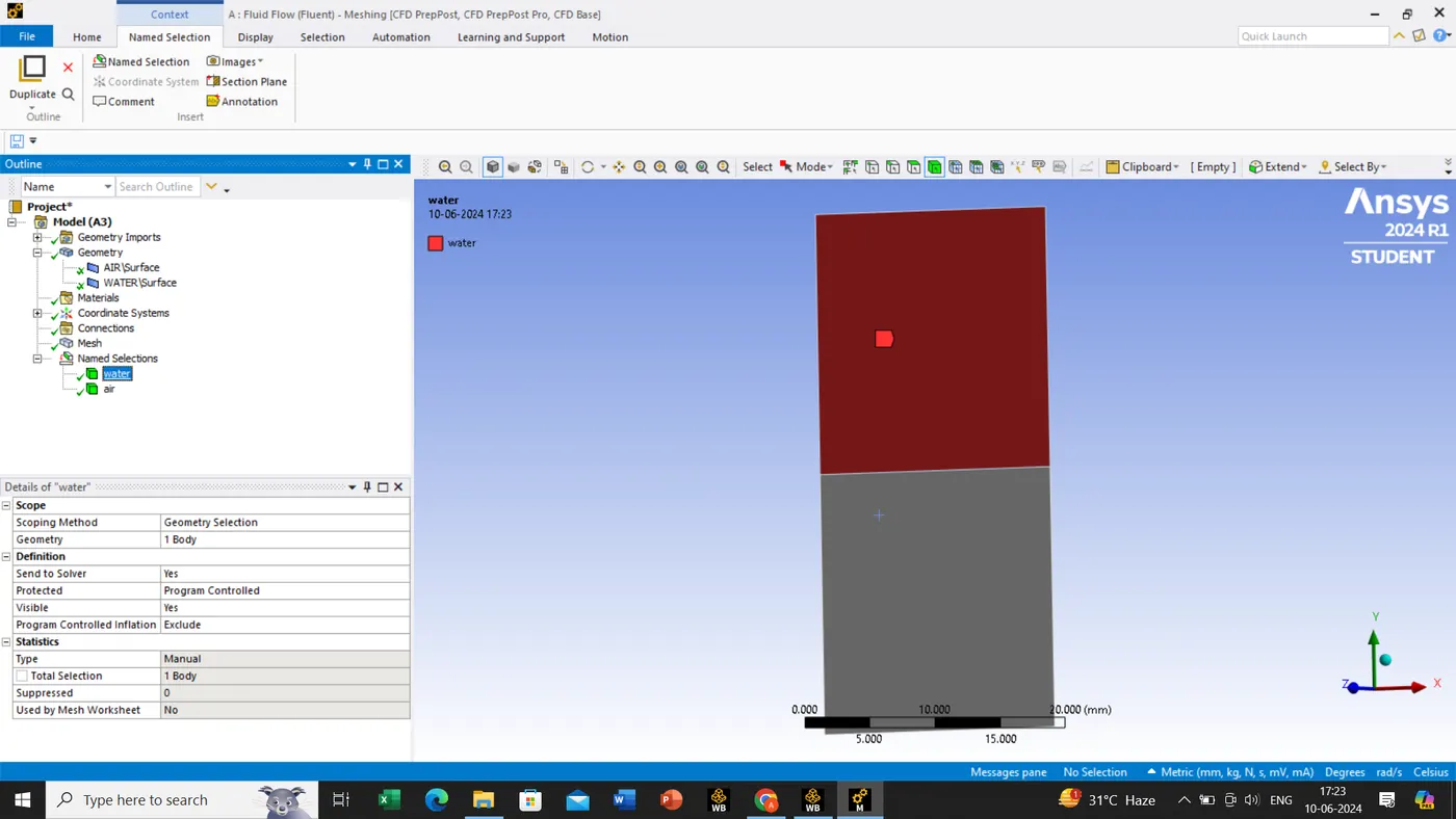
once the meshing tab is open it would take a couple of secs to load our geometry or model. once its done we will input the element size 0.5mm as per our case, after meshing is done check the quality criterion. check the mesh quality is above 5% and later we will assign the names of the squares.
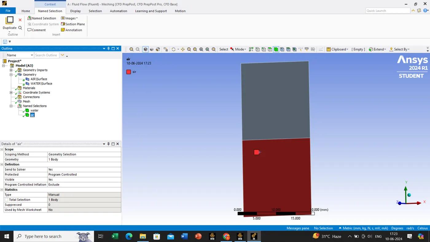
Step:3
ANSYS
After meshing is done we will moving to the ANSYS fluent. we shall be doing general setup as per our laptop/PC configuration.
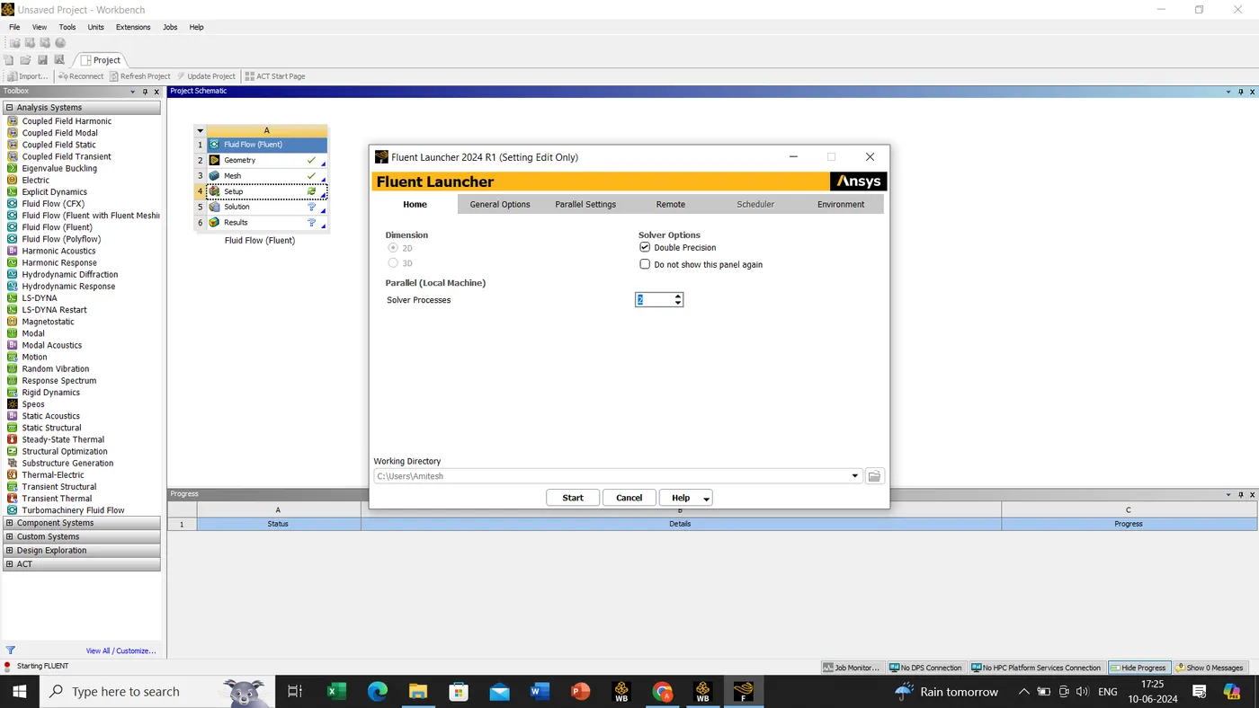
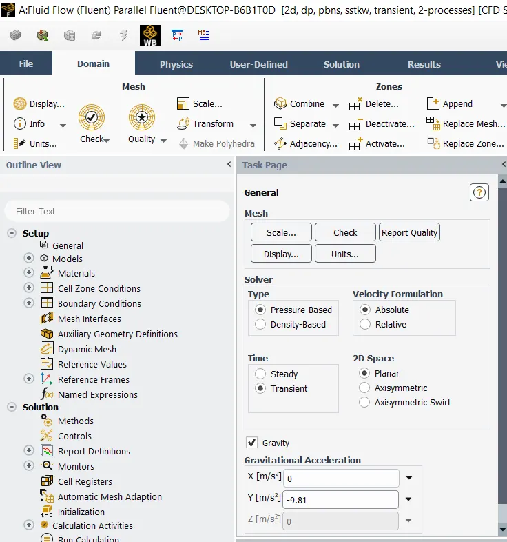
our tab gets open in this we will be selecting the selecting the solver type, time, 2D space and gravity.
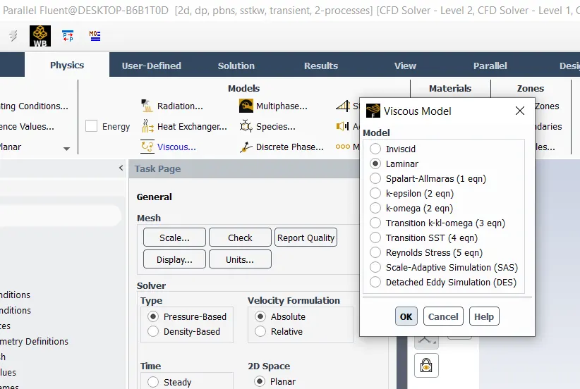
Physics->viscous->Laminar.
Now we have create a material for two as per our case Air, water.
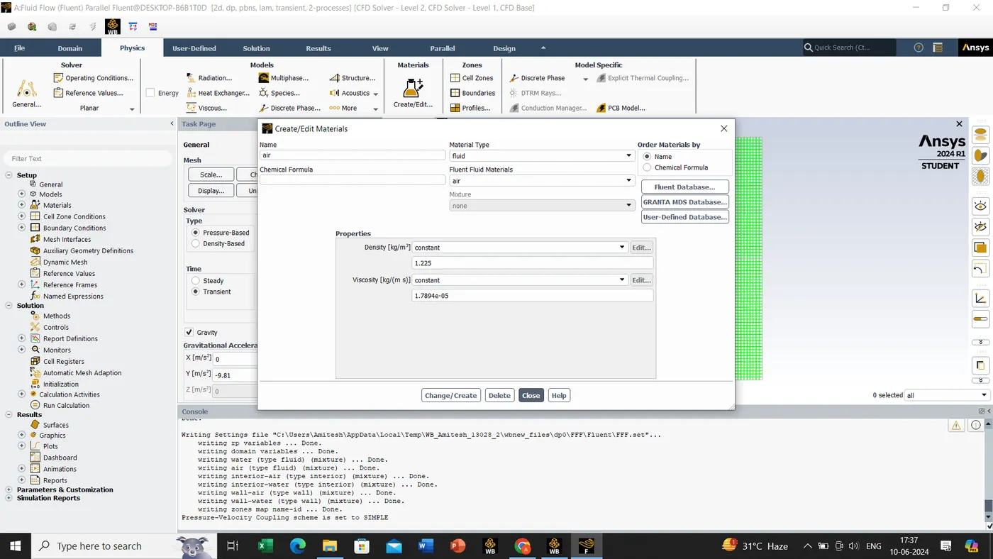
for Air its by default. we have to create a material for water.
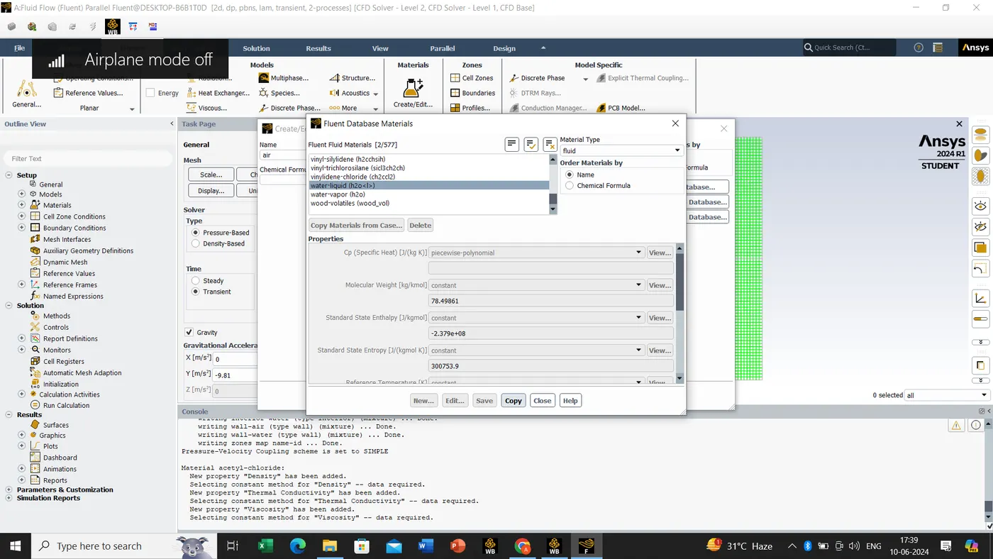
create material->fluent database->search ''water-liquid''->copy button click->close the tab
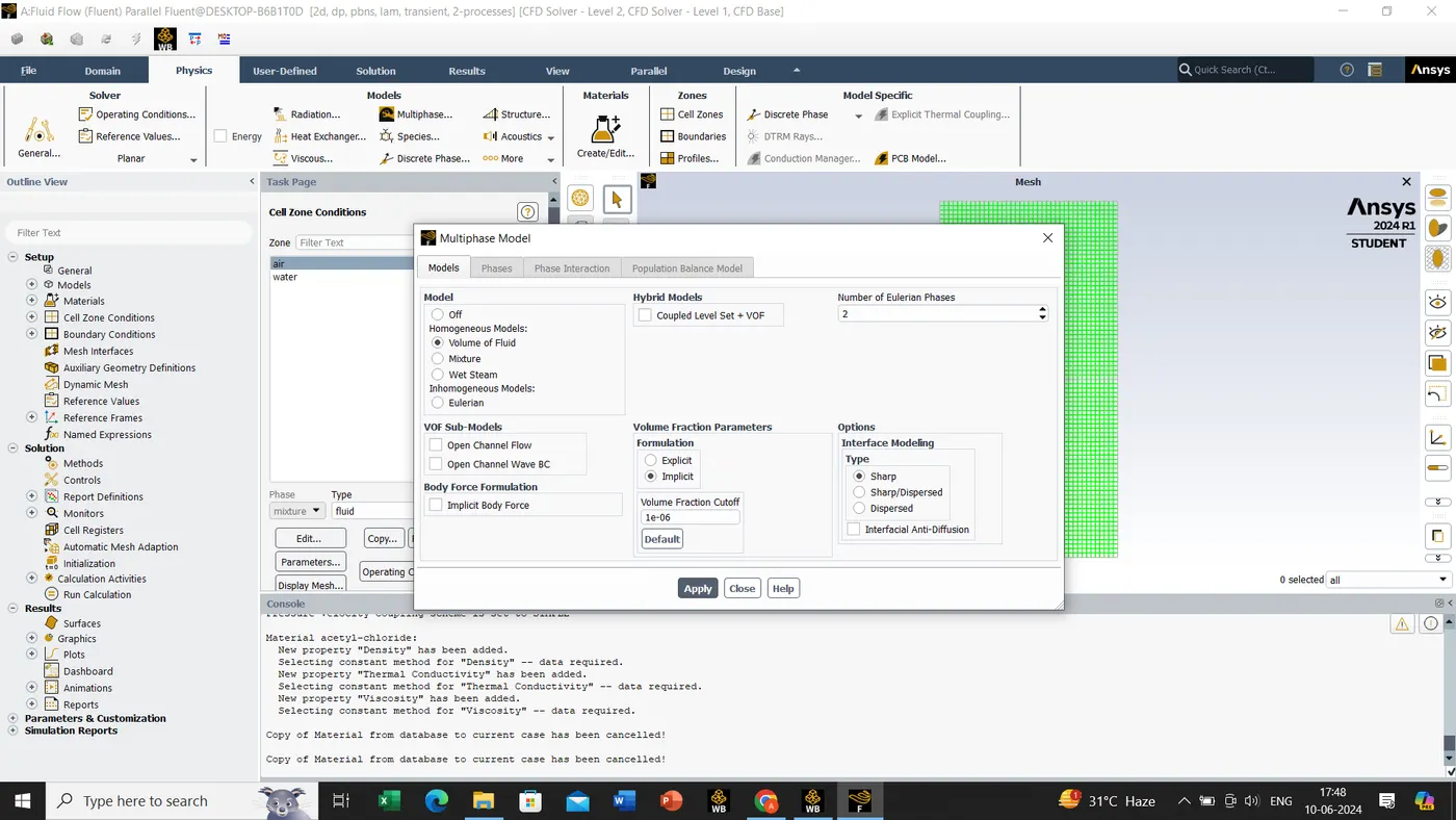
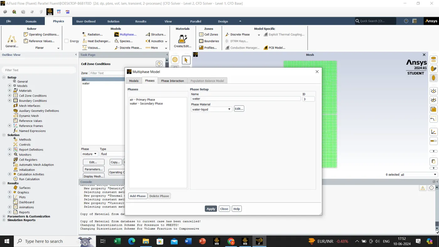
Physics->models->multiphase->volume of fluid->click on implicit->click on apply->assign the primary and secondary phase name.
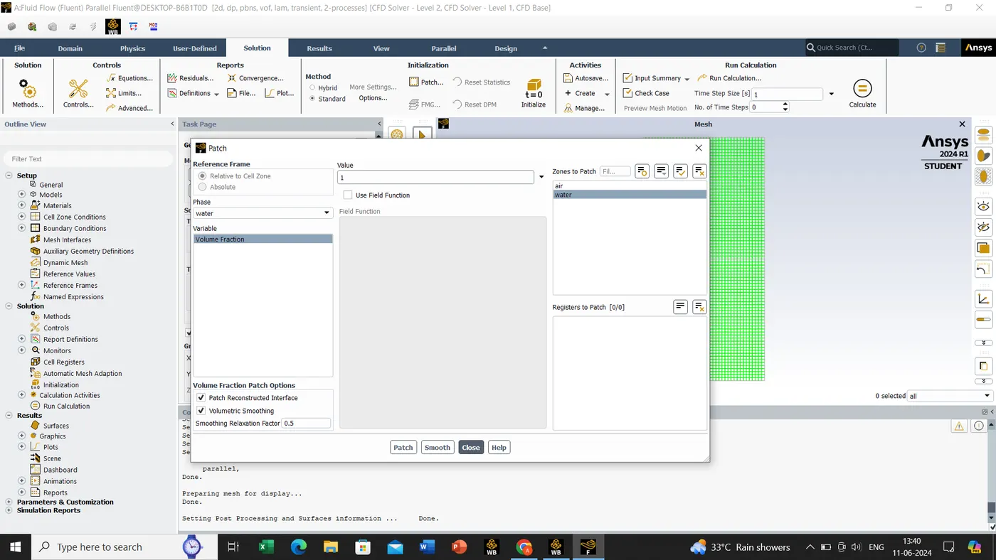
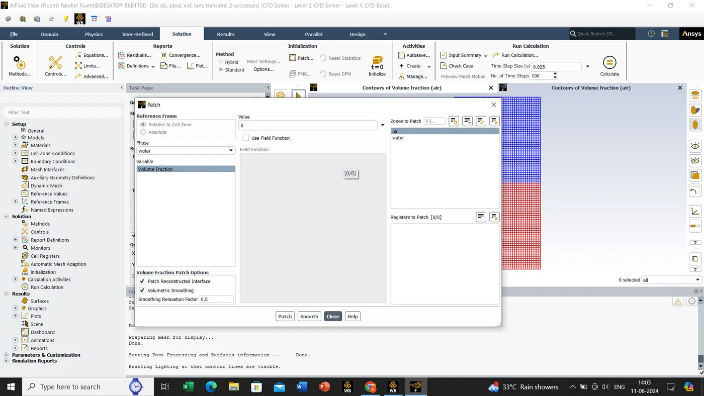
Before using patch tool we have to initialize since after then only the patch tool will be active.
Solving->patch
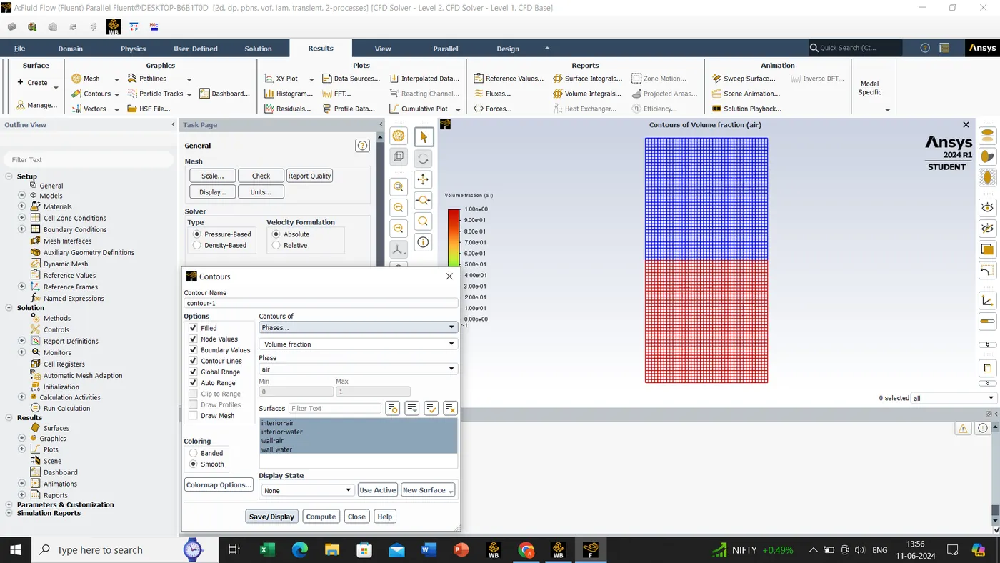
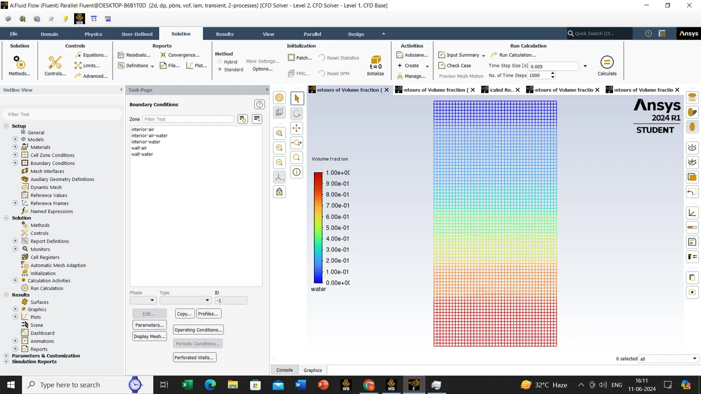
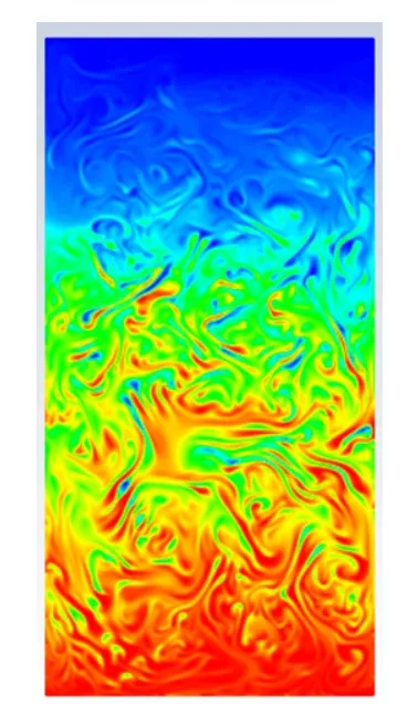
now we have go to contour
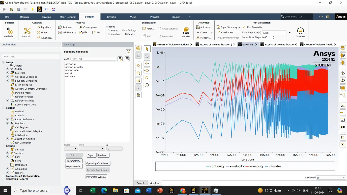
Result->contour
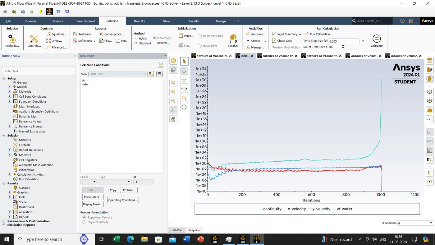
Case 2:-Mesh size- 0.1mm, Water and air
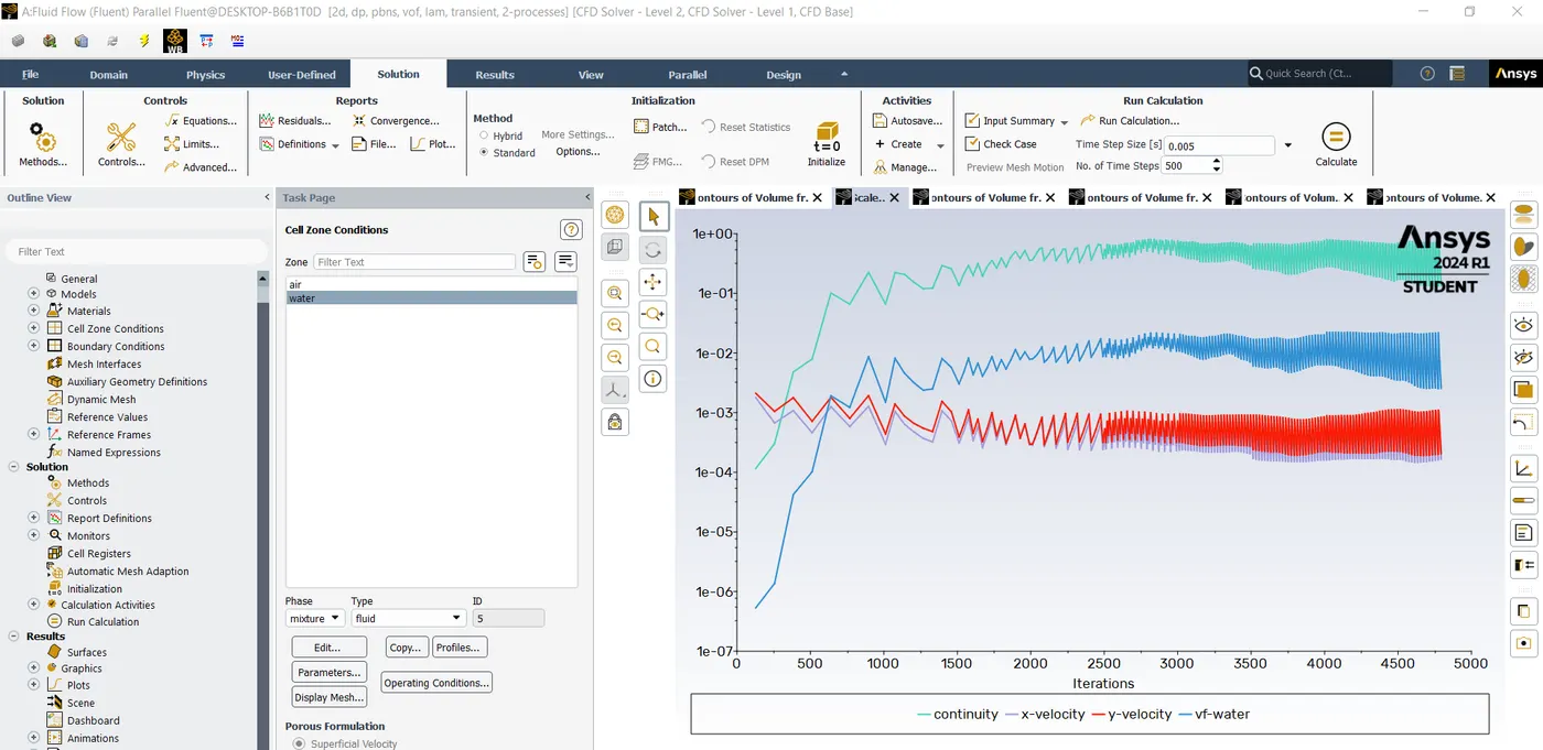
Case 3 : Mesh size- 0.1mm, Water and user defined fluid
Atwood No:-
Atwood no for case 1 and 2
rho1=density of water,
rho2=density of air
A=998.2-1.225/998.2+1.225
A=0.998
Atwood no for case 3
rho1=density of water,
rho2=density of user-defined-material
A=998.2-400/998.2+400
A=0.428
Conclusion:
Atwood number forms a basis to compare and study research papers based on RT Instability. Thus we can use these papers to validate our results for better accuracy.