Week 5 - Rayleigh Taylor Instability
AIM:
Create the model by two completely plane-parallel layers for immiscible fluid, And run the simulation, Then Capture the animation of rayleigh taylor instabilty between two fluid.
OBJECTIVE:
- What are some practical CFD models that have been based on the mathematical analysis of Rayleigh Taylor waves? In your own words, explain how these mathematical models have been adapted for CFD calculations.
Answer:- CFD model for mathematical analysis of rayleigh Taylor waves are:
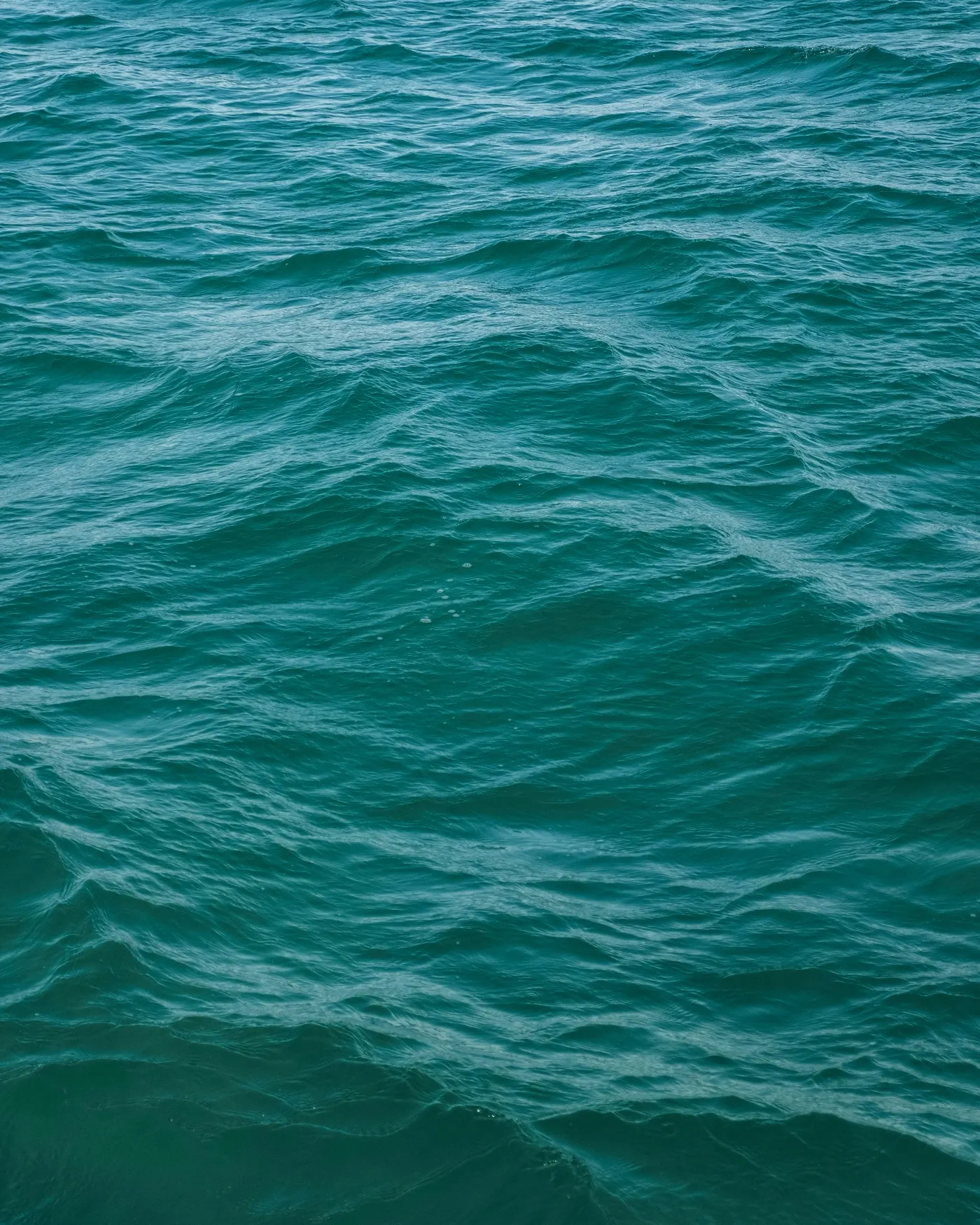
- Kelvin-Helmholtz instability:- Due to velocity shear the fluid shows the Rayleigh taylor instabilty Example:- The waves form on the water surface of the river due to wind
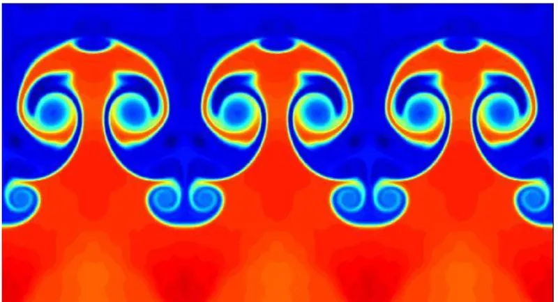
- Richtmyer-Meshkov instability- This occurs when two fluids of different density are impulsively accelerated. Normally this is by the passage of a shock wave. The development of the instability begins with small amplitude perturbations which initially grow linearly with time. This is followed by a nonlinear regime with bubbles appearing in the case of a light fluid penetrating a heavy fluid, and with spikes appearing in the case of a heavy fluid penetrating a light fluid. A chaotic regime eventually is reached and the two fluids mix. This instability can be considered the impulsive-acceleration limit of the Rayleigh Taylor instability.
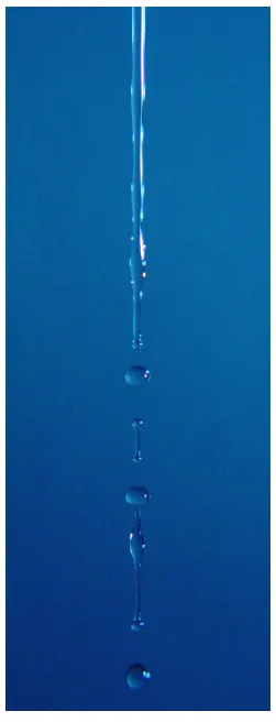
- Plateau-Rayleigh instability-is part of a greater branch of fluid dynamics concerned with fluid thread breakup. This fluid instability is exploited in the design of a particular type of ink jet technology whereby a jet of liquid is perturbed into a steady stream of droplets. The driving force of the Plateau–Rayleigh instability is that liquids, by virtue of their surface tension, tend to minimize their surface area.
Procedure to run the simulation:
- First open geometry space claim window and create water 2D surface container Then in design option add new component to create air 2D surface container So by this two completely plane-parallel layers for immiscible fluid 2D geometry created in geometry space claim window, The final created geometry model is attached in image1
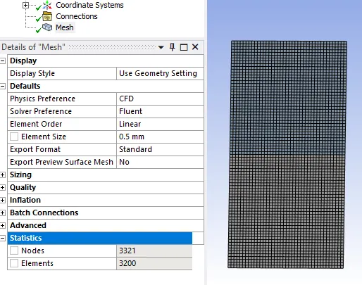
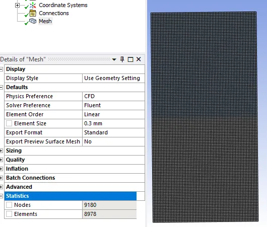
- After close geometry space claim window open mesh window Then generate mesh with given target length This meshed model is shown in image2
- Then close mesh window open setup window There in general task page at the time option change steady into transient condition and enable gravity and give value at y direction -9.81 value
- And in the physics toolbar open viscous option enable laminar flow and using material option select air and water material for simulation
- So After the material selection open multiphase option which is there in physics toolbar enable volume of fluid and change explict mode to implict mode and give apply
- And in same task page go to phases give name for two phases apply and close
- Next intialize and open patch option under phases change mixture into liquid fluid ie. water and at zone dash board list for water give value 1 and patch and for air give value 0 and patch
- Lastly run the simulation for time step size 0.001 with some number of time steps
- So before run the calculation save the time step at autosave to create animation this animation is attached below at image3
- So By this we run the simulation for three case study case1- mesh of 0.5mm with water and air asfluid, Case2- mesh of 0.3mm with water and air as fluid, Case3- mesh of 0.3mm with water and user defined material as fluid
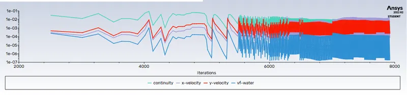
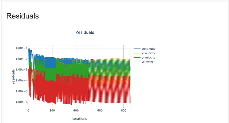
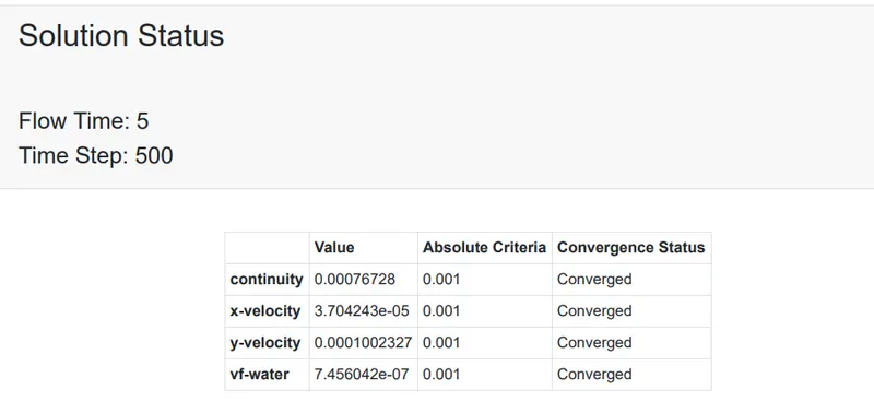
- After simulation we taking out the result, This results value is hown in image4
Result in images:
image1: Geometry
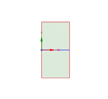
image2: meshed model of different case study
case1 study meshed model
case2 study meshed model
case3 study meshed model
Image3 :animations of three case studies
Case1- mesh of 0.5mm with water and air as fluid
Case2- mesh of 0.3mm with water and air as fluid
Case3- mesh of 0.3mm with water and user defined material as fluid
Image4- result of the three case study:
Case1- Result for the mesh of 0.5mm with water and air as fluid
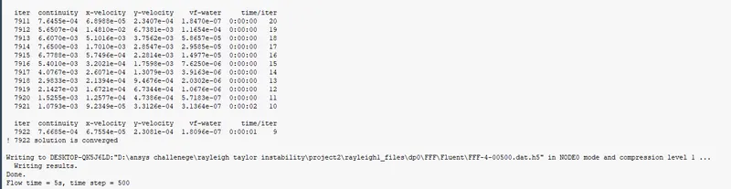
Case2- Result for the mesh of 0.3mm with water and air as fluid
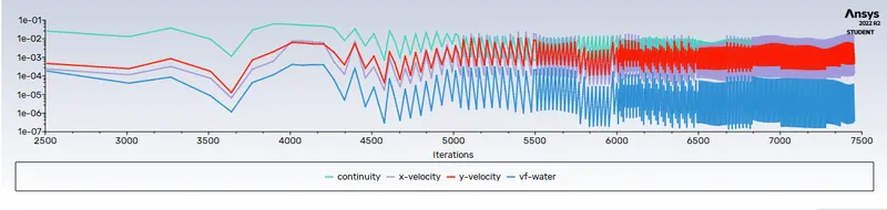
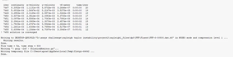
Case3- Result for the mesh of 0.3mm with water and user defined material as fluid
Conclusion:
So by the above procedure rayleigh taylor instability simulation run successfully.