Week 5 - Rayleigh Taylor Instability
AIM- Simulation for Rayleigh Taylor Waves for different mesh sizes , Its implication in CFD and analytical approach comparision with simulations.Define Atwool Number and its Study and values for different cases.
CASE-I : Simulation for mixing of fluids(Air & Water) for Mesh equals to 0.5mm
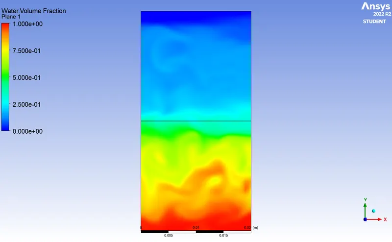
CASE-II : Simulation for mixing of fluids(Air & Water) for Mesh equals 0.1mm
CASE-III : Simulations fro mixing of fluid( User defined fluid & Water) for Mesh equals 0.1 mm
THEORY
Rayleigh Taylor Instability
It is an instability between two different fluids of different densities which occurs when lighter fluid is pushing the heavier fluid. Example like here we will simulate for mixing of Air and Water,Oil and water mixing , Volcanic eruption, nuclear explosion, supernova epxplosions in which expanding core gas is accelerated into denser shell gas and concepts like fusion and fission also similar.
Water suspended oil is an everyday example of Rayleigh-Taylor instability and it may be molded by two completly plane -parallel layers of immiscible fluids,the denser on top of the less dense one and both subject to earth gravity. The equilibrium here is unstable to any pertubrations or disturbances of the interface,If the Heavier fluid is displaced downward with equal volume of lighter lighter fluid will be displaced upwards. The potential energy of the configuration is lower than the initial state. Thus the disturbanceswill grow and lead to further release of potential energy as the more dense material moves down underthe gravitational field,and less dense material is further displaced upwards.
Types of instability and some practical CFD models that have been based on mathematical analysis of Rayleigh Taylor waves were:
Ritchmyer-Meshkov instability
It arises when a shock wave interacts with an interface seprating two different fluids.It combines compressible phenomenon such as shock interaction and reflection,with hydrodynamic instability,including non-linear growth and subsequent transitionaccross wide range of mach number.
Kelvin-Helmholtz instability
This occurs when velocity shear in a single continuous fluid or where there is a velocity difference across the interface between 2 fluids.An example is wind wind blowing over water.
Plateau-rayleigh instability
It explains why and how a falling stream of fluid breaks up into smaller packets with the same volume but less surface area. This fluid instability is exploited in the design of particular type of inkjet technology where by a jet of liquid is perturbed into a steady stream droplets.
MTEHODS APPROACH
- Open spaceclaim to create geometry.
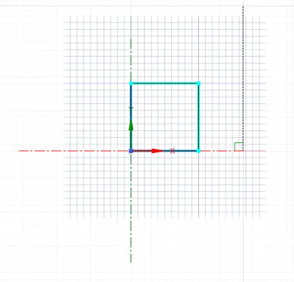
- Create geometry in XY plane of square 20 mm and select pull toolto make surface of that.
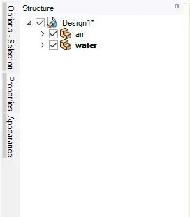
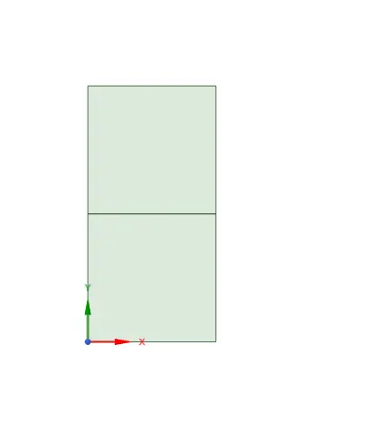
- Move Geometry into new compnent and name it as air. Then create same geometry for Water compnent at same edge of Air .
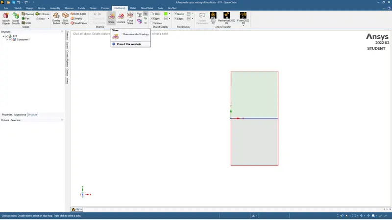
- Then 2 box will share one common edge .Then we use Share topology to share domains for each other.
- Then we create mesh fo each case 0f 0.5 and 0.1 mm .
- Then we open geometry in solver ANSYS-FLUENT.
- We give transient method with acceleration of -9.81 in y direction. and laminar flow in general settings.
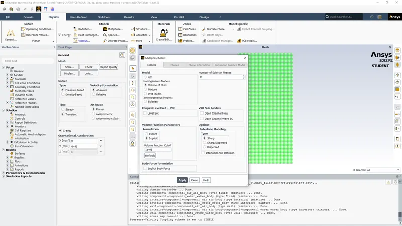
- We turn on energy equation and choose multiphase .In multiphase model we choose volume of fluid model and implicit model.
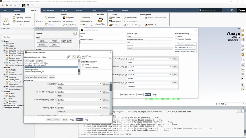
- Then we add material using fluent database and then assign primary as Air and Secondary as Water.
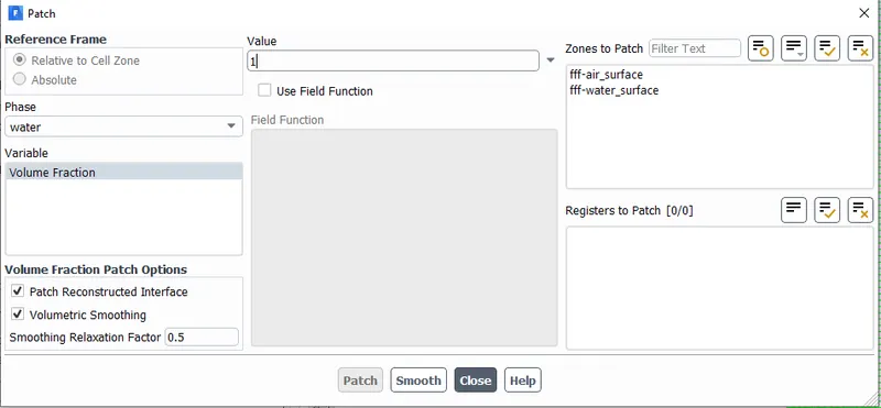
- we initailize the solution then we use patch option to give water volume fraction value as 1 and air as 0.
- We create contour for water volume fraction using phases and create animation using the Result .
PROCEDURE
CASE 1- Mixing of air and water for mesh 0.5mm
Geometry
we create geomety in spaceclaim
We create 2 components Air and water
We create water body and create surface.
Then we use share topology
Meshing
We just generate mesh for 0.5 mm
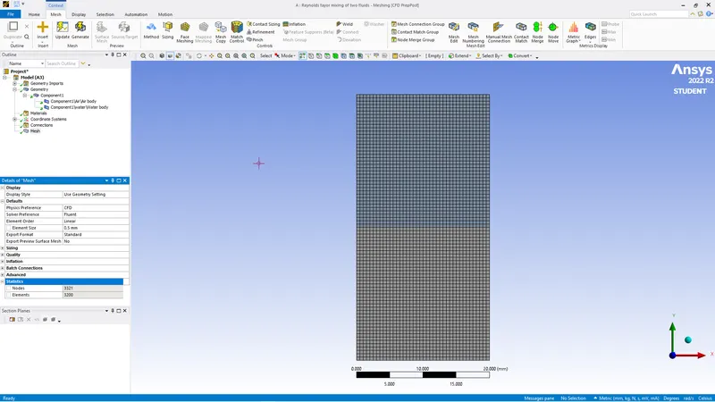
Solver
We give general settings as shown below and mentiond in methods.
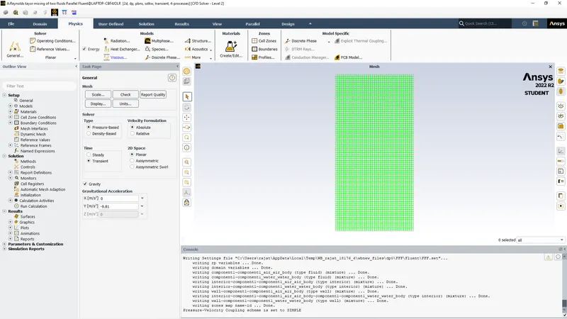
Then we add new material of water using materials option
After we use multiphase and assign volume of fluid method using implicit option
Then we asisgn phases to air and water primary to air and secondary to water
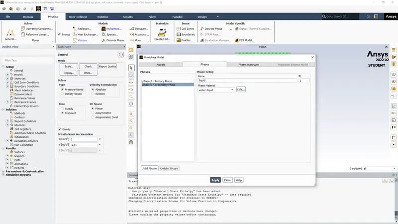
Then we initialize the solution and patch the volumes to show the data for different properties volume
Then we choose auto save to create animation of each time step in results.
we choose time time step 0.01 & no of time steps 500 which will create data for 5 seconds.
RESULTS
Residuals 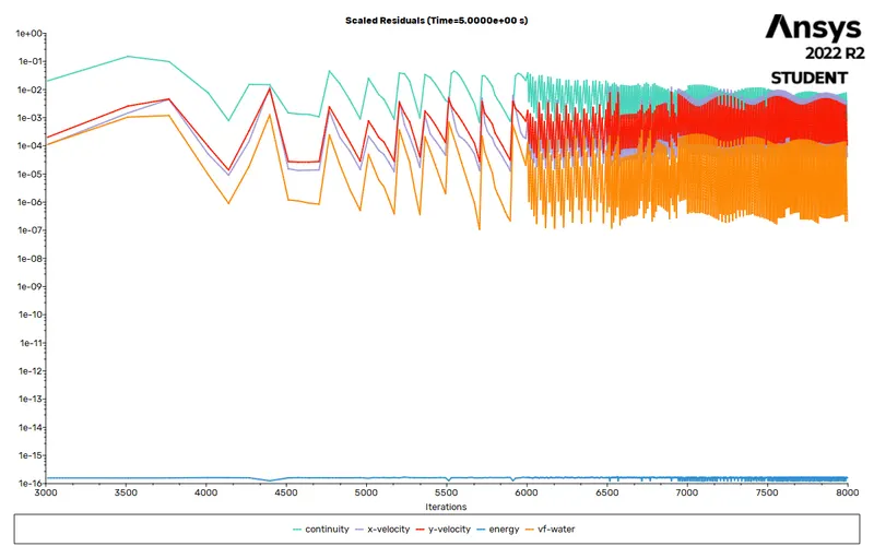
BETWEEN SIMULATION POST
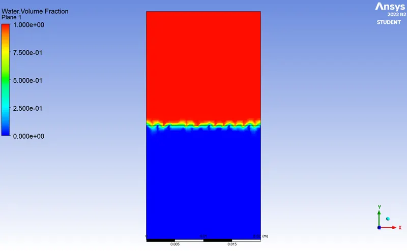
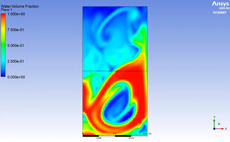
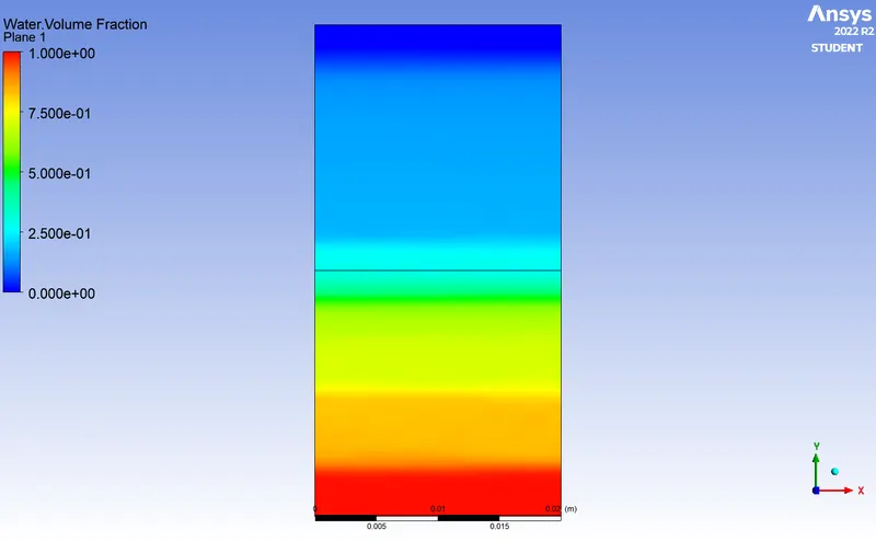
At final we can see the fluid water settling below and air at above.
LINK FOR ANIMATION CASE 1-https://drive.google.com/file/d/1CPhur4qyqPBJAbyGs4vu_tXdT-TeFAAE/view?usp=sharing
CASE 2 (FOR MESH 0.1MM)
Mesh 0.1mm
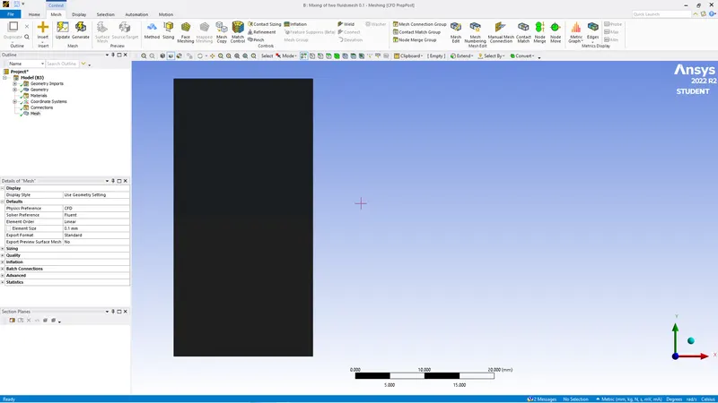
residual plot
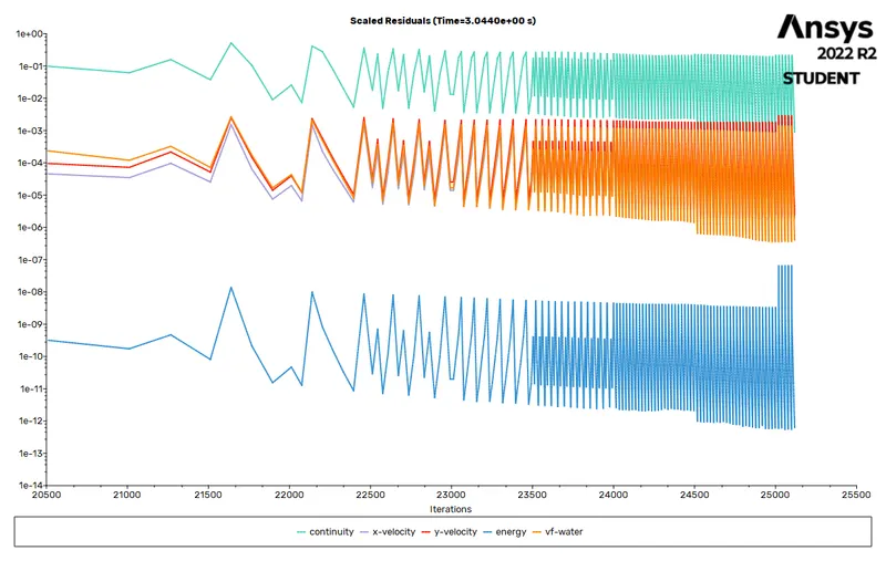
As the size is small we need smaller time step otherwise it will show floating error so we start at 0.001 time steo for 500 time no. Then we increase to 0.002 for 1000 time no and then 0.003 for 500.
CFD posts
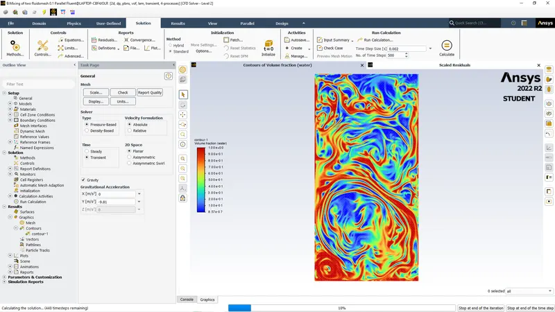
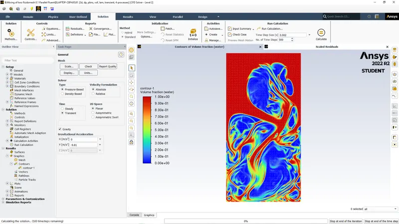
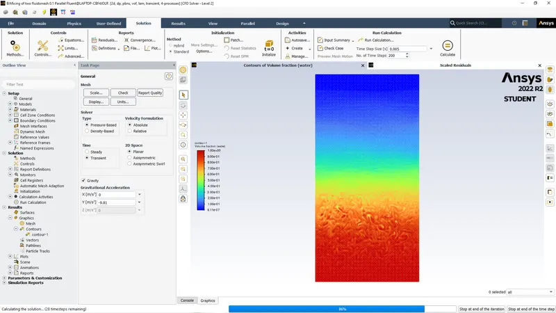
As we can see by updting mesh size the quality of simulation will show more details but will take more computational time.
LINK FOR CASE 2 ANIMATION- https://drive.google.com/file/d/1JESEGoaAysxWaGB7vuw8P1-CLlL9239M/view?usp=sharing
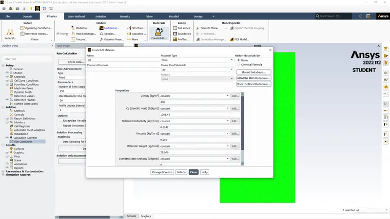
CASE-III( MESH=0.1MM ,Mixing of 2 fluids water and user defined with density= 400 kg/m^3 and viscosity = 0.001kg/m-s)
Mesh
Solver
creating user defined material
Residual plot
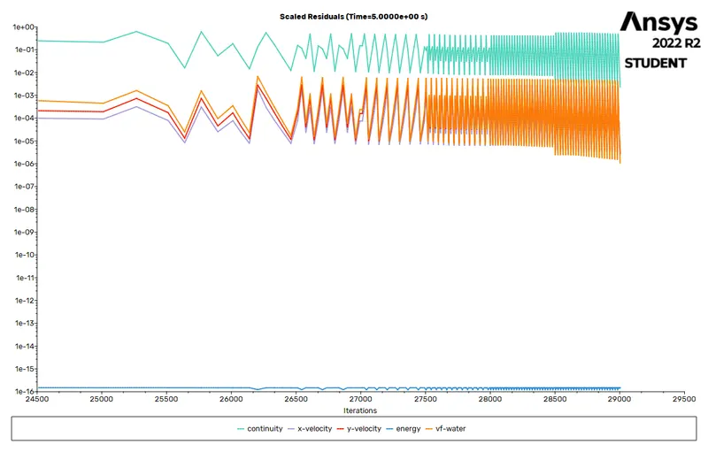
As the density is more than air the fluid will take more time to merge and take their positions accordingly we need much more iterations
time step= 0.001 & time size = 1000
time step= 0.002 & time size = 1000
time step= 0.004 & time size = 500
time step= 0.004 & time size = 500
Where the other 3 cases took 3 to 4 seconds to submerge this simulation will take approx 5-7 seconds.
CFD reults.
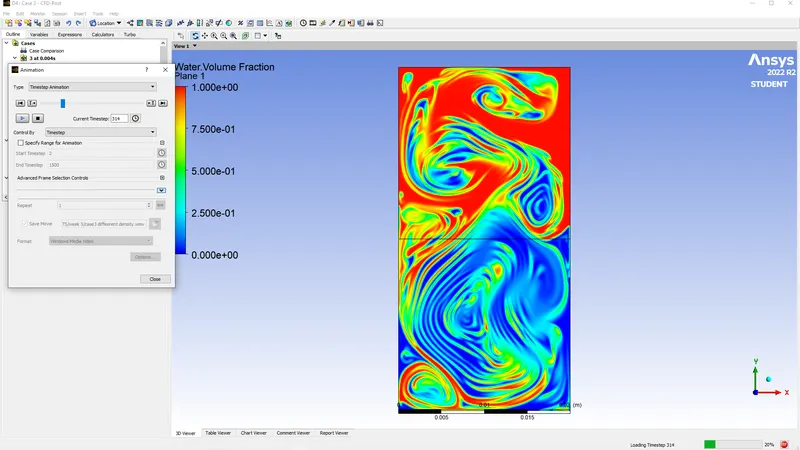
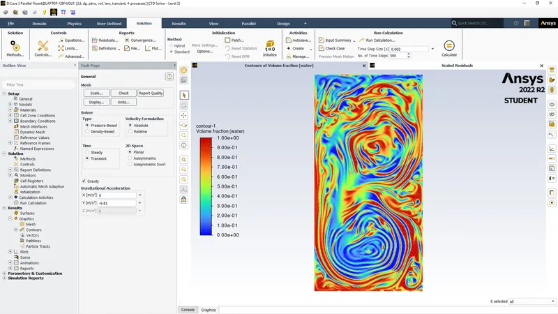
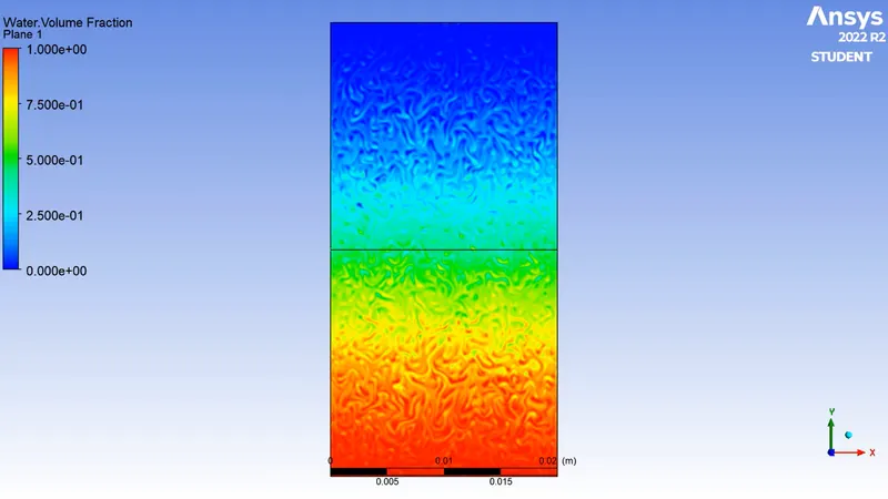
As we discussed in rayleigh taylor instability the denser fluid will submerge with layer to layer it not completely submerge as 1 but will create independent layers firm due to high density and viscosity as visble in contour.
LINK FOR ANIMATION CASE 3- https://drive.google.com/file/d/1O0spHGGsLBZ8WzJR-nA4ShORL26lNisq/view?usp=sharing
Conclusions
As discussed in Rayelighs taylor the heavier fluid will submerge towards downward and lighter fluid upwards.We can clearly see the process happening in all 3 cases as in all 3 cases water is heavier fluid.In all simulations key points of importance are:-
- The finer the mesh size the quality of submerging fluids is more detailed and correct.
- But finer the mesh more computaional time is needed.
- In 3rd case we changed the properties and due to fuid was more denser than air its mixing procedure was different form above 2 cases.
- In 3rd case the layer of fluids were formed due to denser fluids as we see in oil and water submerging. we could see layer and bubles formation at initial stages due to gravitaional pull But denser fluid and high viscosity of fluid was the reason.
- If the primary fluid was more denser than water we would not see any movement in fluid .
ATWOOL NUMBER
The atwool number is a dimensionaless number in fluid dynamics used in study of hydrodynamic instabilities in densities stratified flows. Its a density ratio defined as
A= `(rho1 -rho2)/(rho1 + rho2`
where
`rho1`= density of heavier liquid
`rho2`= density of lighter fluid
FOR CASE 1 &2
`rho1`= 998.2`(kg)/m^3`(water)
`rho2`= 1.225 `(kg)/m^3`(air)
A= 998.2 - 1.225/998.2+1.225
A= 0.997
FOR CASE 3
`rho1`= 998.2`(kg)/m^3`(water)
`rho2`= 400 `(kg)/m^3`(air)
A= 998.2-400/998.2+400
A= 0.427
The difference in the fluid densities divided by their sum is defined as Atwool number.