Week 5 - Rayleigh Taylor Instability
The Rayleigh-Taylor instability( RT instability) is an instability of an interface between two fluids of different densities which is caused because of the lighter fluid pushes the heavier fluid. e.g. behaviour of water suspended above oil in earth's gravity, mushroom clouds from volcanic eruptions, atmospheric nuclear explosions.
Below are the practical CFD models that have been based on the mjathematical analysis of Rayleigh Taylor waves and how these models have been implemented in CFD applications.
a) Saffman Taylor instability: It is also called as viscous fingering, it is formation of patterns in morphologically unstable interface between two fluids in a porous medium. This situation is most often encountered in drainage process through soil. It occurs when less viscous fluid is injected , displacing more viscous fluid. But it does not occur in reverse situation of more viscous fluid displacing the other, in this type the interface is stable and no any insutability will be seen. Rayleigh-Taylor criterion is similar but it occurs without injection of fluid and here the interface is horizontal with gravity. Also, heavier fluid is over the lighter one.
b) Richtmyer-Meshkov instability : It occurs when two fluids with different densities are impulsively accelerated. Normally this is by the passege of shock waves. The development of instability begins with small amplitude with initially grow linearly with time. The chaotic regime is reached and two fluids mix.
c) Mushroom cloud: It is mushroom shaped cloud of debris, smoke and condensed water vapour resulted from large explosions. The effect is most commonly associated with nuclear explosion.
they also can be caused by powerful convensional weapons, like thermobayric weapons. Some volcanic eruptions or impact events can produce natural mushroom clouds.
They form by sudden formation of large volume of lower density gases at any altitude, causing a Rayleigh-Tylor instability. The buoyant mass of gas rises rapidly , results in vortice curling downwards wround its edges forming temporary vortex ring. The mass of the gas plus entrained moist air reaches an altitude where it is no longer of lower density than the surrounding air, at this point it disperses, drifts back downwards.
d) Kelvin-Helmholtz instability: It typically occurs when there is velocity difference across the interface between two fluids or velocity shear in a single continuous fluid. e.g. when air blows over water, the instability consutant manifests as waves.
Simulation for 2 different mesh sizes with basleine 0.5mm size
Geometry:
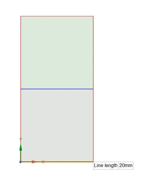
Shared topology is enabled. SpaceClaim can share topology (edge, face, node )between intersecting bodies.
Shared topology is only way to acheive conformal mesh where bodies meet and is way to make sure that intersection area of bodies is meshed properly.
case_1 : Simulation with mesh size 0.5mm
Meshing details:
Element type: Qaud
Element size: 0.5 mm
Mesh statistics:
No of elements: 3200
No of nodes: 3321
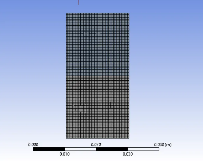
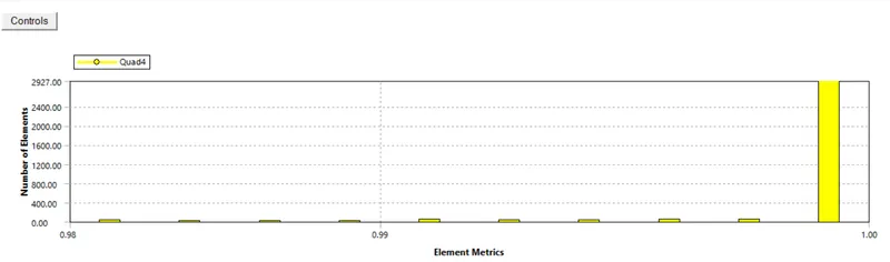
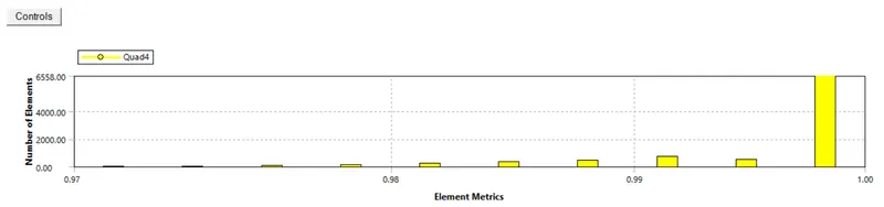
Mesh Quality :
Setup :
Model: Volume of Fluid
Formulation: Implicit
Phases: a) Primary phase : air
b) Secondary phase: Water
Solver: Pressure based
Time: Transient
Fluid: Water and air
Viscous model: K-omega SST
Gravity: On -9.81m /s2 in y direction.
Time step: 0.005 s
No. of time steps: 1500
Solution :
Once standard initialization is done, patching will be done. Initially volume fractions for water. air kept as 1, 0 on water amount basis.
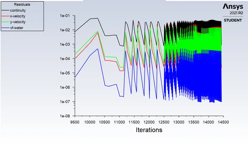
Residual plot
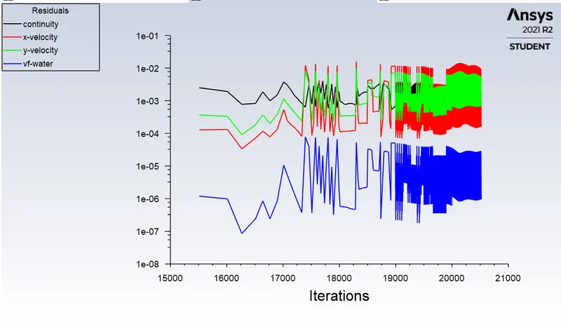
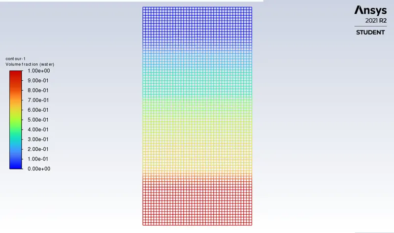
Link of video animation : https://drive.google.com/file/d/1JYpFCE4I-FFgYngbeoe7zEpplTdcdQHj/view?usp=sharing
case_2 : Simulation with mesh size 0.4 mm
Meshing details:
Element type: Qaud
Element size: 0.4 mm
Mesh statistics:
No of elements: 5000
No of nodes: 5151
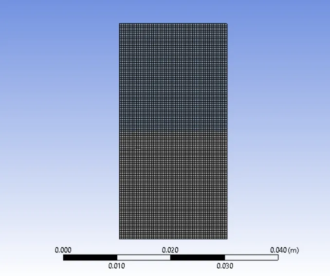
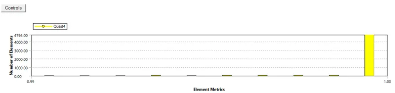
Setup same as case 1.
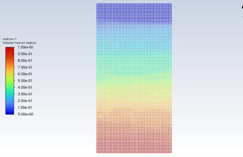
Results:
Residual plot:
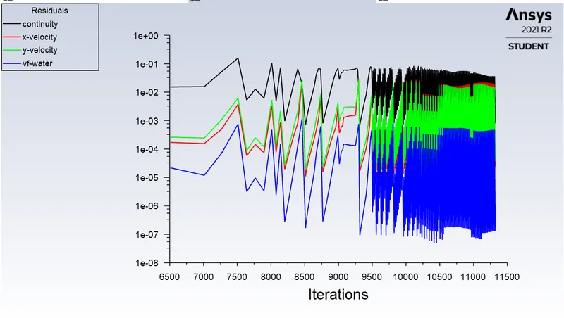
Results:
Residual plot:
Link of video animation: https://drive.google.com/file/d/1Ggllj01f0ox4RWpHFtwRUuhQPid0WAgh/view?usp=sharing
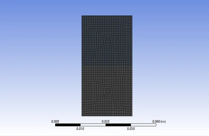
case_3 : Simulation with mesh size 0.3 mm
Meshing details:
Element type: Qaud
Element size: 0.3 mm
Mesh statistics:
No of elements: 8978
No of nodes: 9180
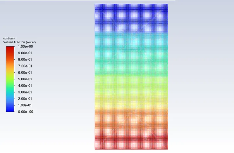
Link of video animation: https://drive.google.com/file/d/1Ggllj01f0ox4RWpHFtwRUuhQPid0WAgh/view?usp=sharing
case_4 : Simulation with mesh size 0.3 mm with water and user-defined material
Meshing is same as case_3
Results:
Residual plot:
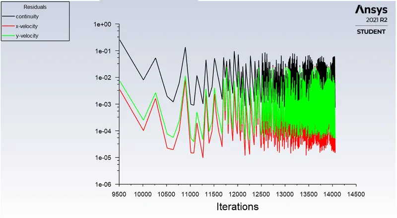
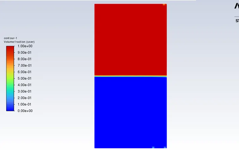
Link of animation video: https://drive.google.com/file/d/1qIL1eoEFDmgzC0rzI8T9W8dshm7YkSKr/view?usp=sharing
Effect of mesh size on simulation:
- Accuracy of volume fraction values are enhanced in cases 2 and 3 comparatively, with meshes refined further.
- The quality of animations is improved by refining mesh and we get smoother results.
- Computation time in second and third cases are comparatively higher as mesh is refined further. Whether to go for very fine mesh depends on the economy of the project and application.
Why steady-state approach is not sutaible for these types of simulations? (for air & water here)
Steady state is a process when the properties of flow does not change with respect to time (state ). But Rayleigh-Taylor instability varies with respect to time. RT instability CFD models involve turbulent flow and are subjected to extrenal conditions.
In transient state, we can also get intermediate solution at particular time step, whereas in steady, we get solution only at last of iterations , but not in between.
Transient simluation takes more time and hence it requires more space.
Define Atwood number :
It is dimensionless number which describes the density difference between two adjecant fluids with a common interface.
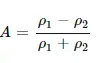
where ρ1 = Density pf heavier fluid
ρ2 = Density of ligher fluid
Atwood number for Baseline mesh (case1) and refined meshes (case2 and case 3)
Density_air = 1.225 kg/m3
Density_water = 998.2 kg/m3
A = 0.9975
Atwood number for water and user-defined material with finer mesh
Density_water = 998.2 kg/m3
Density_user_material = 400 kg/m3
A =0.4278
Explaination of variation in Atwood number in above two cases affecting behaviour of instability
- In case of RT stability simulation for water and air (with refined mesh), Atwood number 0.9975 is close to 1. For A close to 1, the ligher fluid( air) much below heavier fluid (water) takes the form of larger bubble like plumes which can be seen in the animation video.
- In case of RT stability simulation for water and user defined fluid (with refined mesh), Atwood number 0.4278 is close to 0. Hence, RT stability takes form of symmetric fingers of fluid which can be observed from video.