Week - 5 - Modelling Spotwelds
AIM: Model the spotweld using the beam and solid elements and compare the results.
PROCEDURE:
- First the download the model and open the keyword file and check what are the keywords in the keyword manager.
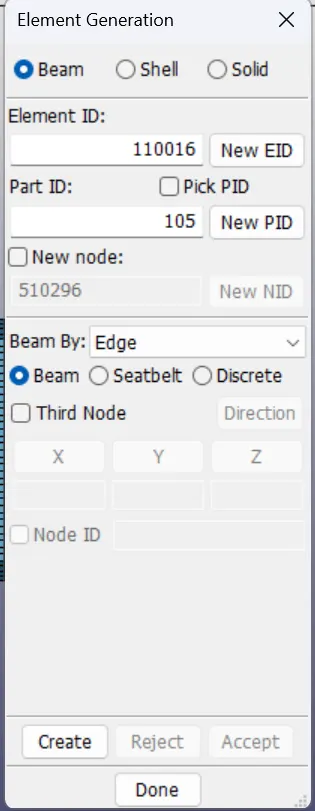
- Then from the element generation option the beam element is created based on the given location in the challenge. For the solid element also we need to follow the same procedure.
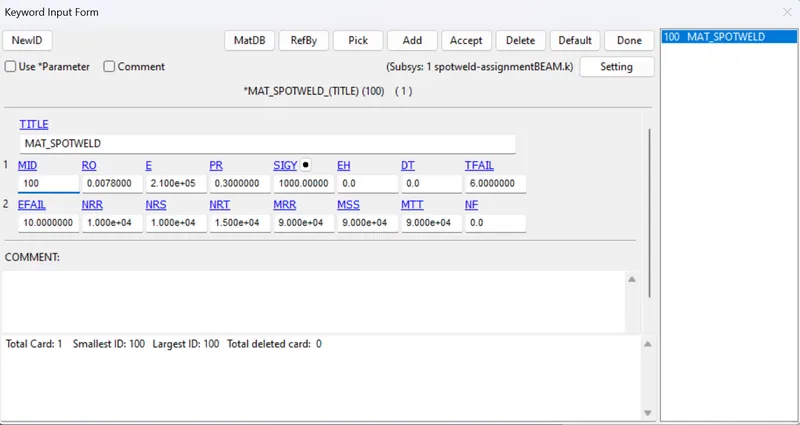
- The material card used for spotweld is MAT_100 card and give the required options in that card.
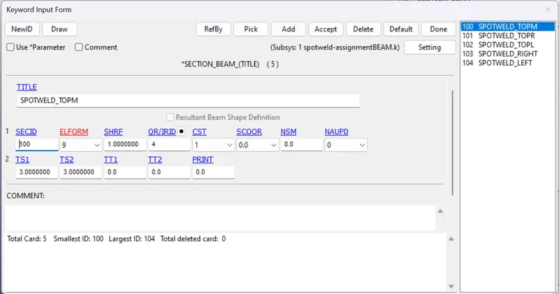
- The section card used for spotweld is Beam for beam element and for solid element it is solid and for parts the shell section is used.
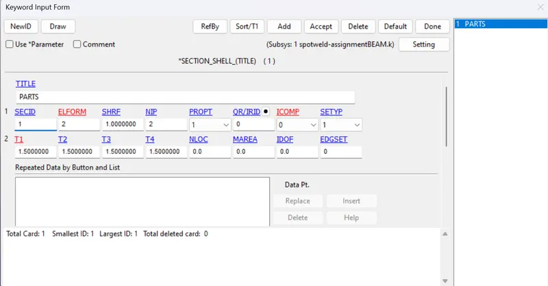
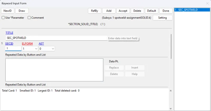
- Assign the material and section to their respective parts in the part module.
- The contact has to be defined for the beam/solid to the top and bottom shell parts by Contact tied shell edge to surface/ Contact tied surface to surface card in the contact card and the slave nodes/shells are the nodes/ shells of their respective beam/solid element.
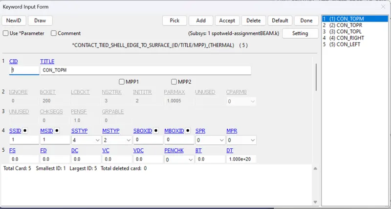
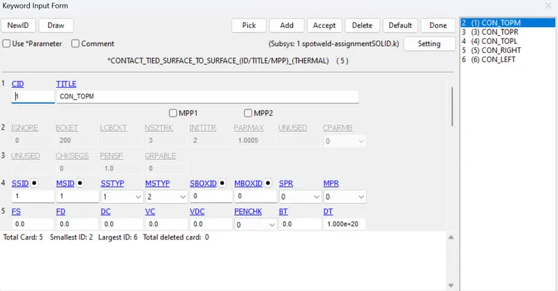
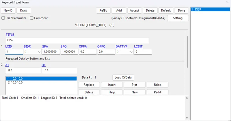
- The bottom part is fixed by using the spc boundary and fix all the DOFs, top part is moved to a distance of 10mm. For defining this load curve is created using the DEFINE_CURVE.
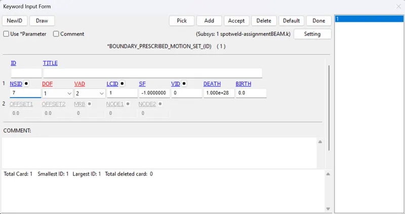
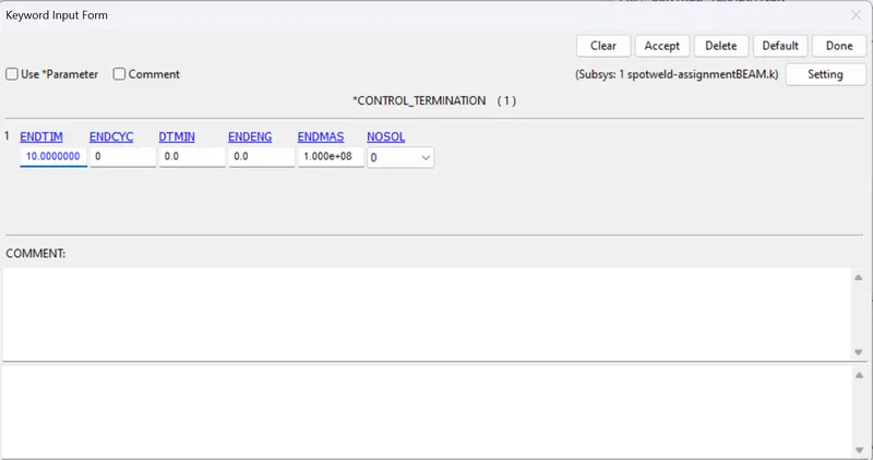
- The Termination time as 10ms is given in the CONTROL_TERMINATION card.
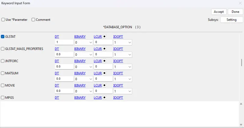
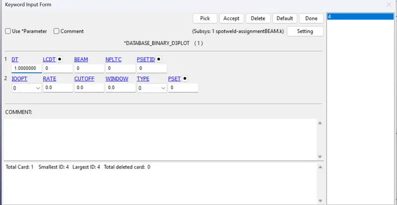
- The otputs has to be requested by using the ASCII and BINARY_D3PLOT by giving the time interval as 1ms.
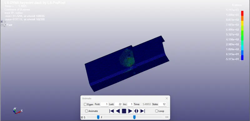
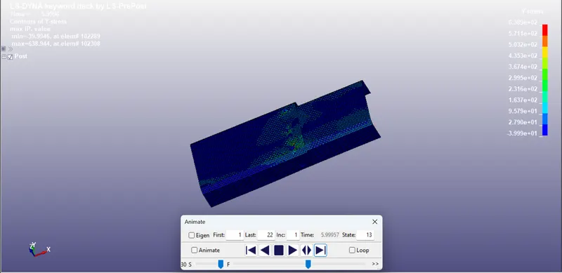
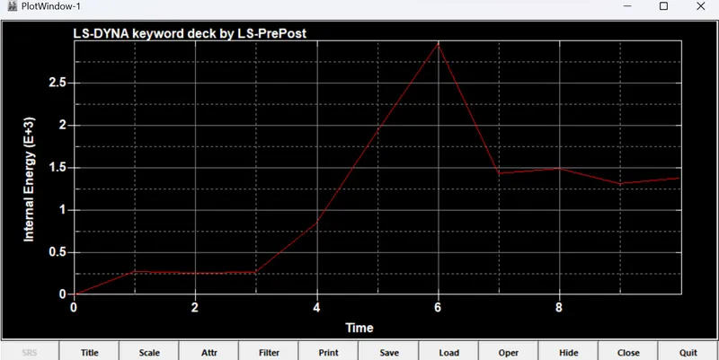
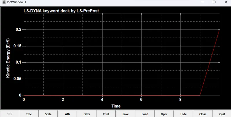
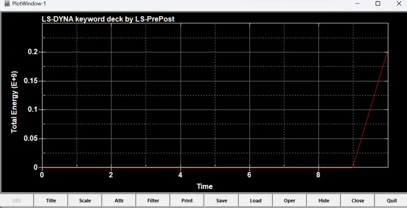
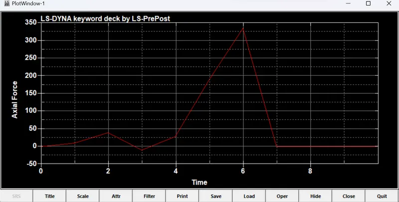
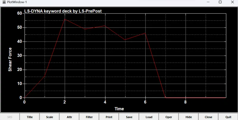
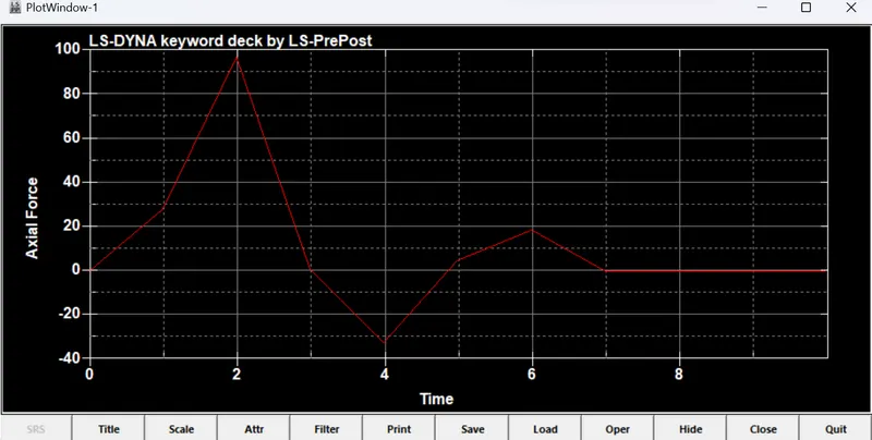
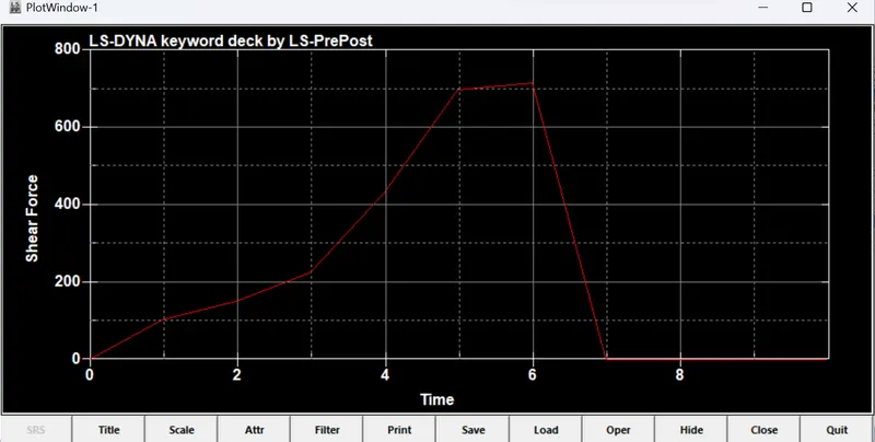
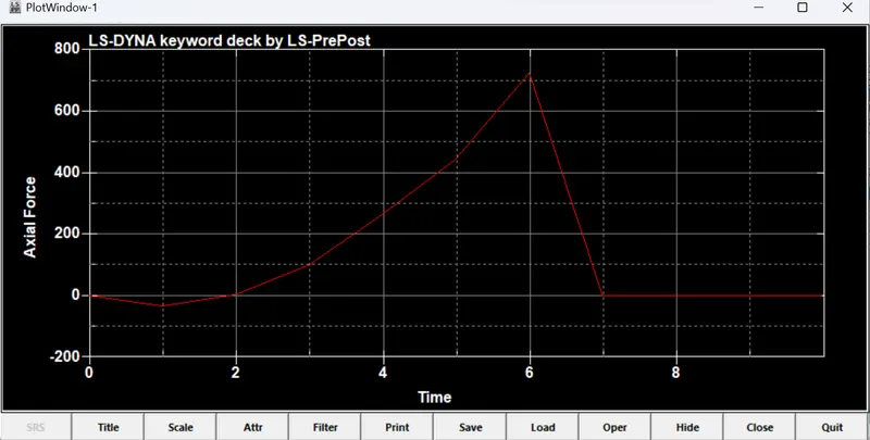
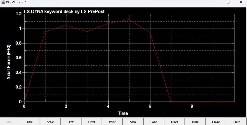
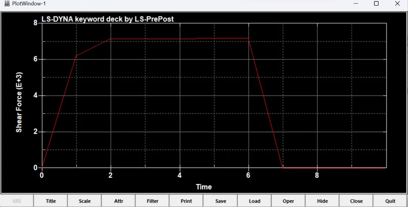
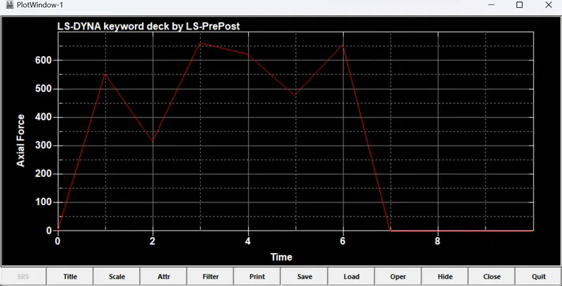
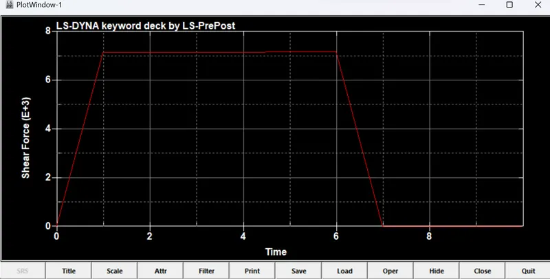
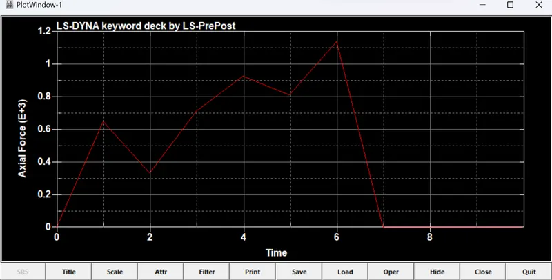
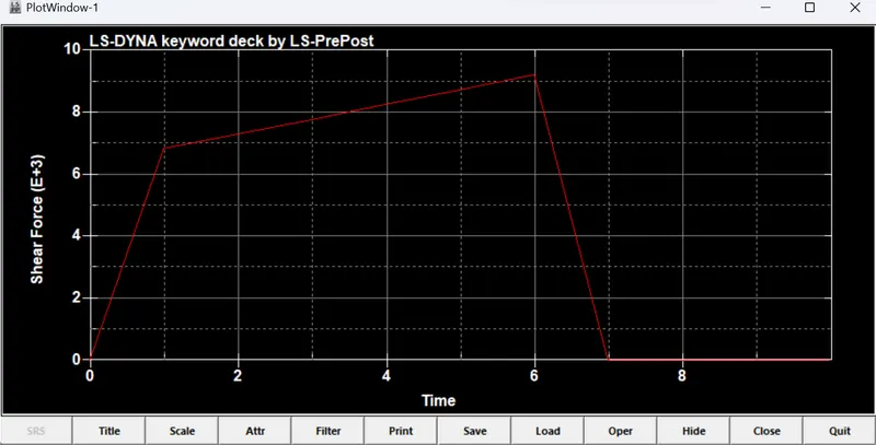
- The results for the BEAM spotweld are given in the following figures and plots.
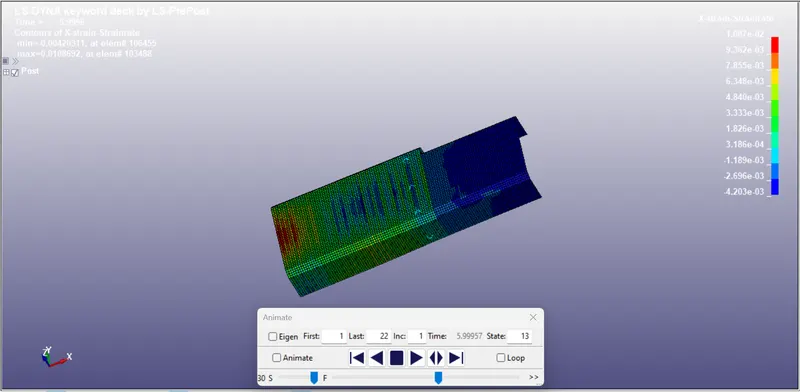
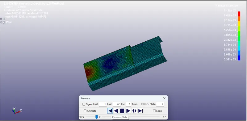
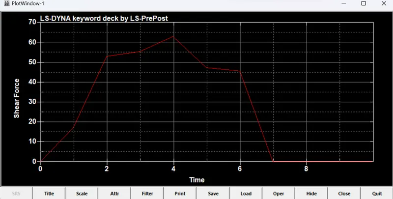
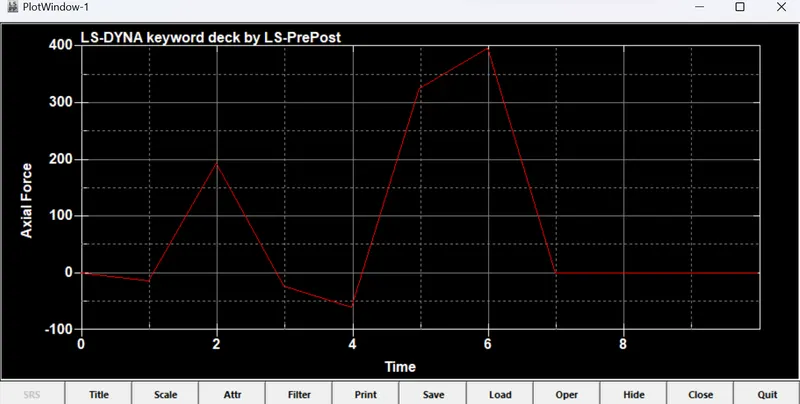
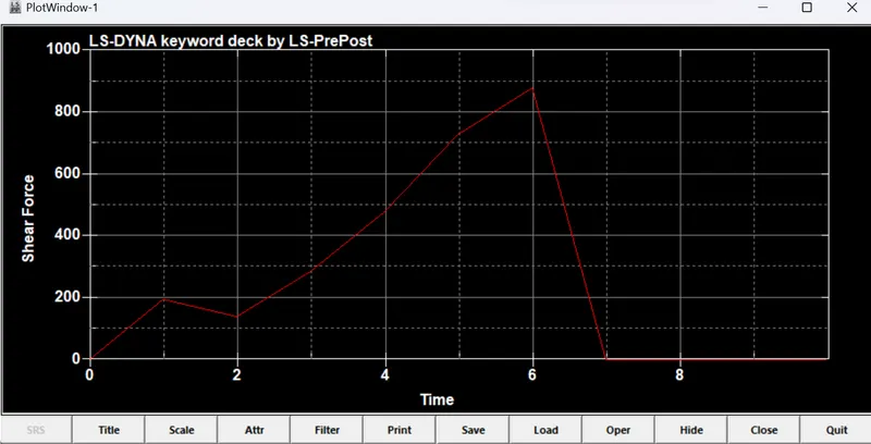
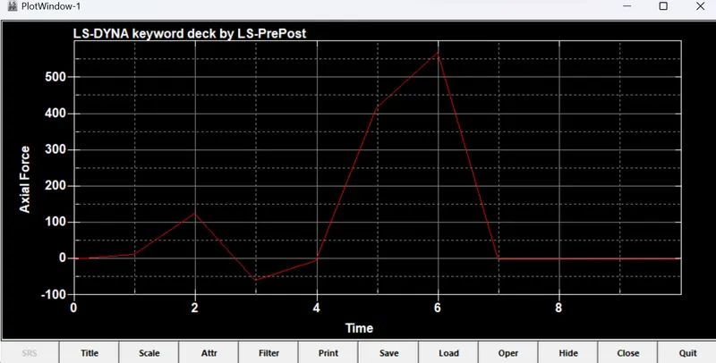
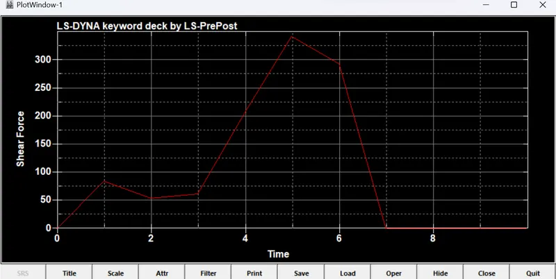
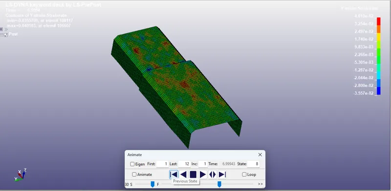
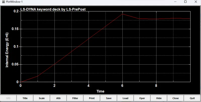
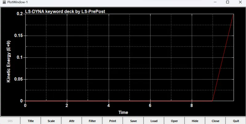
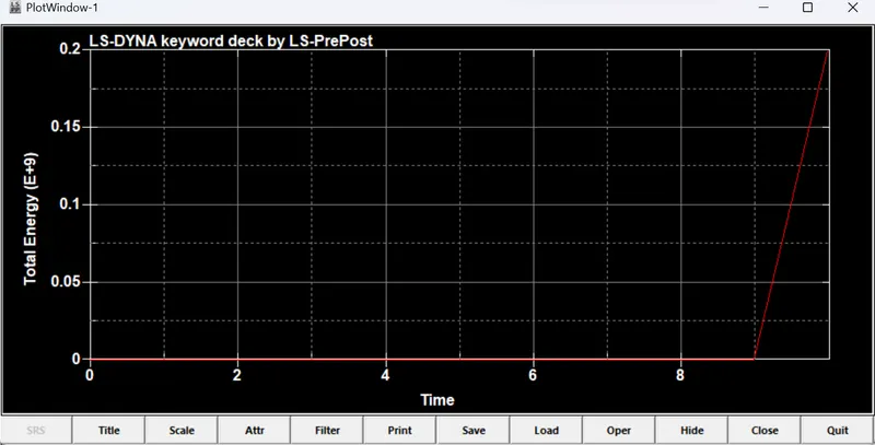
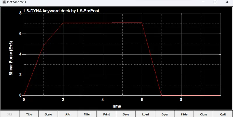
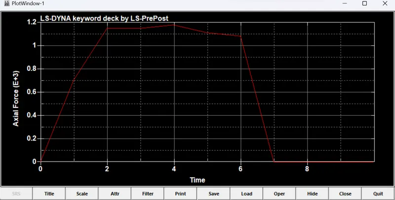
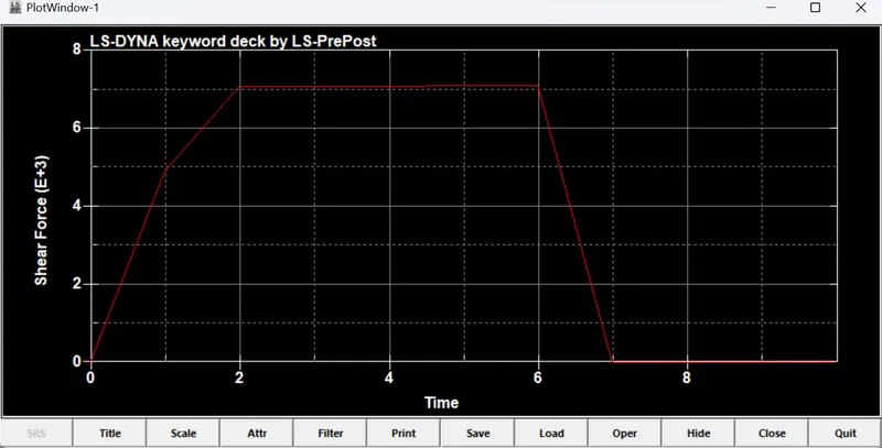
- The results for the SOLID spotweld are given in the following figures and plots.
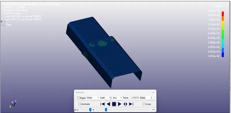
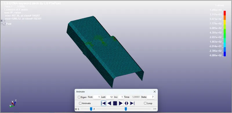
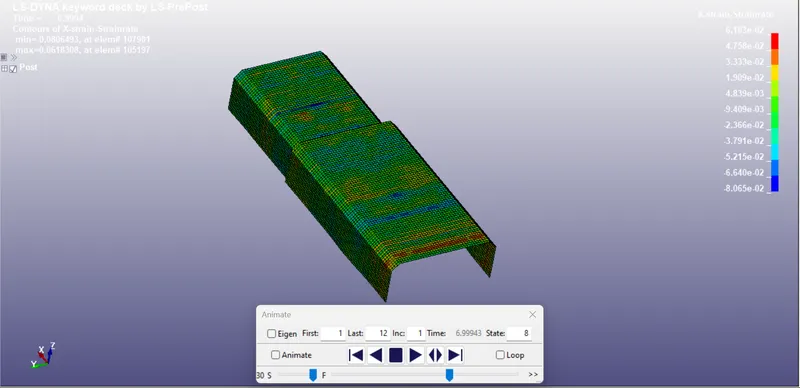

OBSERVATIONS:
- The axial force generated using the solid element is 3 times more than the beam elements.
- The shear force generated using the solid element is also 9 times more than the beam elements.
CONCLUSIONS: Spotweld is modelled for the given parts in 5 different locations using the BEAM element and SOLID element and the required outputs has been shown in the figures and plots.