Week - 5 - Modelling Spotwelds
AIM: To create a spotweld in the seatbelt model and to ensure the strength of the weld by creating 2 different Beams and Solid weld spots in it and analyzing the difference in LS-DYNA.
Procedure:
i) Common for both Beam and solid spotweld elements:
ii) Import the model into LS-DYNA
iii) Check for the keyword which is assigned to it.
iv) Create a New beam element by choosing the nodes in the Top and Bottom plates of the model.
or
Create a New Solid element by choosing the nodes in the Top and Bottom plates of the model.
v) Create a Set of nodes for the assigned nodes, Set part.
vi) Nodes which are needed to be Constrained as a wall to select.
vii)Create a new Material and Section ID for spotweld with proper regulation.
viii) Create a contact to the surface and nodes for which the flow of motion will not collapse.
ix) Create a control termination and Database for the proper output.
x) Check for Keyword check-up and Run the simulation.
xi) If the termination is normal, then run the final output file in LS-DYNA.
Theory:
Spot Welding is a type of resisting welding technique that comes under the fusion welding category where heat and pressure both are applied in order to join two parts, the heat produced due to the resistance of current flow through the material air gap, the heat generated is equal to I^2R and nugget formation happen and then when held for few fractions of seconds the fusion between the part happens.
Spot weld strength plays a crucial importance in the overall vehicle structural integrity and crash safety. With the innovation of Advanced high-strength steel (AHSS), the prediction of spot-weld fracture is of paramount importance in current and future vehicle design.
Resistive spot welding (RSW) is the most common joining method in the automotive industry, particularly for BIW applications. The main advantage of using RSW include high speed, low cost, and the ability to volume automation. A typical vehicle contains approximately 2000-5000 spot welds. The joining strength is important to the overall structural integrity and vehicle crash safety.
Today automotive industry is mindful of reducing CO2 emissions and increasing fuel efficiency. To achieve these objectives, automakers are continuously working to reduce the overall vehicle weight.
Extensive use of Advanced High-strength steel (AHSS) BIW is one of the ways to achieve this goal with the most recent innovation in AHSS, the automotive industry has been able to use a combination of low-gage and high-strength steel to design lightweight body structures, However joining High-strength steel becomes challenging with lower gages, considering spot weld strength directly proportional to the thickness of underlying sheet metal. Hence, spot-weld failure prediction during the virtual design stage of vehicle development is of vital importance.
Failure Criteria:
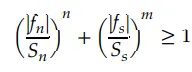
Where fn and fs are the normal and shear interface forces, component fn is the non-zero for tensile value only.
Sn is the normal force at spot weld failure
Ss is the shear force at spot weld failure
Fn is something that we can say generated force and the Sn is the limit basically that we specify
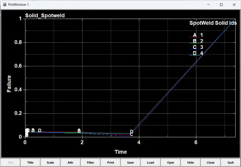
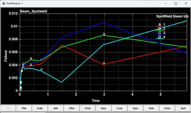
Failure Time: When the failure time, TF, is reached the spot weld becomes inactive and the constrained nodes may move freely.
Modelling of a Spotweld:
Crashworthiness is described as the ability of the vehicular structure to absorb kinetic energy and minimize injury to the passengers during the collision and is considered among the important criteria in determining vehicle design with regard to passenger safety.
There is a thin line between the Crash and Impact. The crash is also a type of impact, but when there is the involvement of human beings then that study is termed a crash
The FE simulation helps engineer how components interact in an assembly and how the failure mode and mechanism are developed during impact loading.
Among many different possibilities to model a spot weld, in crashworthiness there are three modelling techniques have been investigated, a single beam element, four hexahedron elements and a single hexahedron element, it is obvious that using a beam element is the easiest discretization effort to model spot welds with finite elements, Here we found that the overall stiffness depends strongly on the position where the beam nodes are connected to the shell surfaces, secondly the torsion stiffness of beam can’t be activated, since the corresponding degree of freedom is not available in the attached shell formulation.
Considering the spot weld discretization with four hexahedron elements, the smallest element size would decrease the time step too much and additional mass to counterbalance this by using mass scaling is not acceptable.
The third modelling technique consists of one single hexahedron, here the available option were found not accurate enough in most cases.
Procedure:
CASE 1:
Import of model:
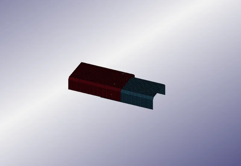
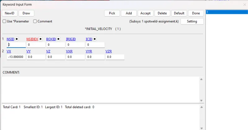
Here we have to create a spotweld, pulling impact on one side of the wall by assigning the velocity of 13.89mm/ms or 50kmph.
Creating of Nodes:
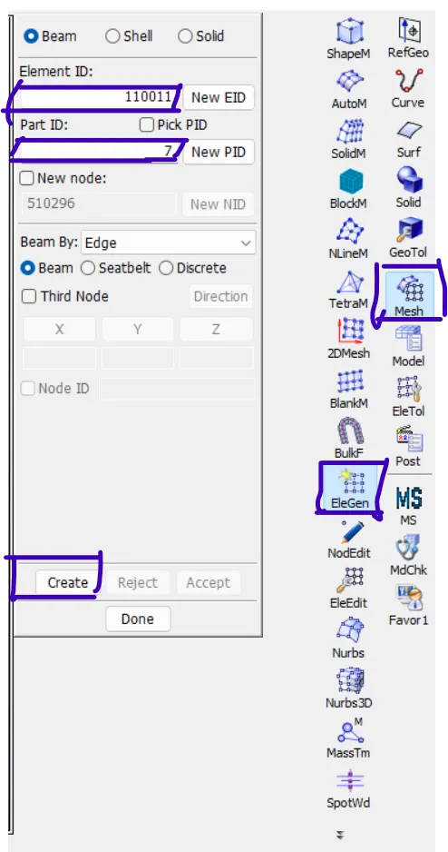
Select the nodes that we need beam or spot weld in FE, choosing both the top and bottom plate.
Mesh -> EleGen -> Select Element ID & Part ID -> Choose the Nodes -> Create
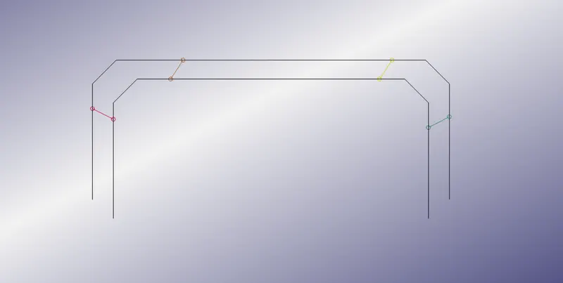
The beam element which was created is in the form:
Defining the velocity of the Top plate:
Since the Bottom plate is set to constrain
Creating of Contact:
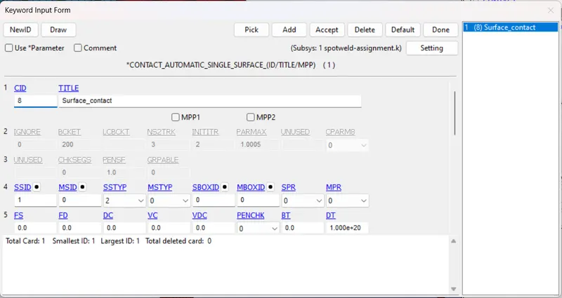
We create a contact between the surface to ensure the weld is been attached to both plates in the proper manner.
In LS-DYNA there are various kinds of contact are available in which Automatic_Single_Surface is used and assigned to the displacement plate in which when the collision happens the two surfaces shouldn't come into contact.
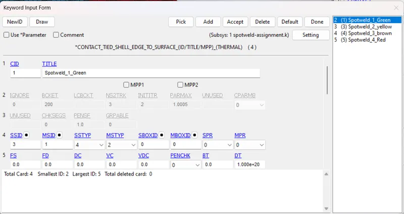
Contact_Tied_Shell_Edge_To_Surface is used to give the contact of the beam element to both the plates.
Control Termination:
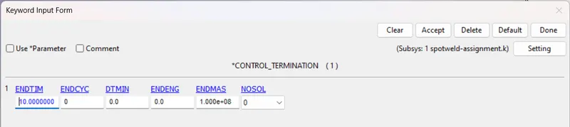
The control termination is set to 10ms so that simulation will take place for 10ms.
DATABASE:
All required output we can get as output plot by using Database keywords
a. BINARY-D3PLOT
This is the most important keyword where the output of the animation file is written (.d3plot).
For our simulation, we specify a time interval of 0.5, which represents that for each 0.5 ms the output data of the analysis is written onto the d3plot file.
b. ASCII-Option
Here the required output parameters that need to be computed are specified and written in a separate file. In our case, the following files are written for every time interval of 0.5 ms,
GLSTAT - Global Statistics involving KE, IE, hourglass energy, etc.
NODOUT - Nodal properties like displacement, acceleration, etc.
SLEOUT - Sliding interface energies
SECFORCE - Cross-sectional forces
SWFORCE - Spotweld Nodal Constraint Reaction Forces
ELOUT- element results
CASE 2:
Some keywords are been changed for the solid models, in which instead of beam here we create Solid in the element generation.
Material, Part, control card, etc are similar to the beam element.
SPOTWELD ELEMENT GENERATION:
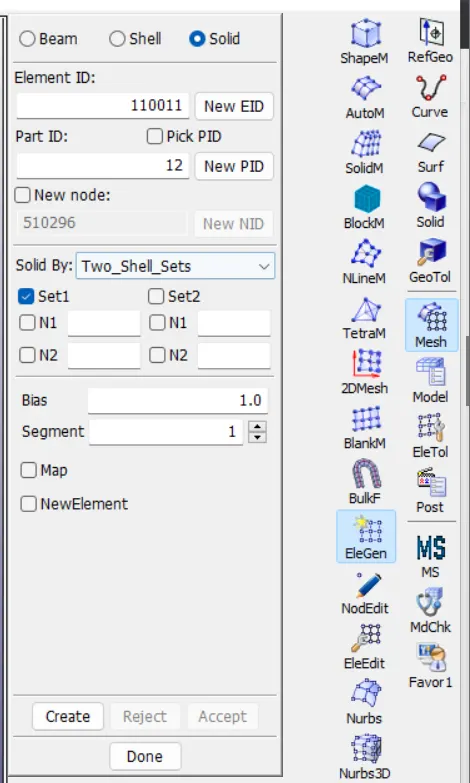
To generate the Solid Spotweld,
Mesh -> EleGen -> Solid -> solid by -> Two_shell_sets -> choose the element sets.
Section Card:
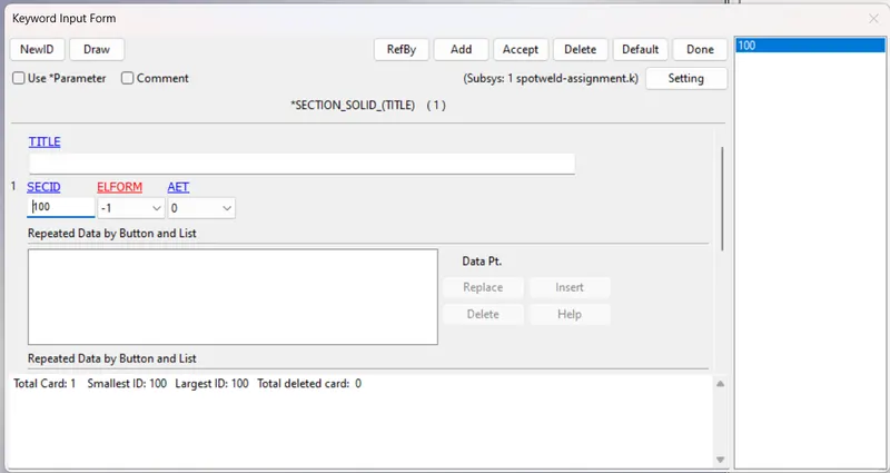
Same as for beam elements the solid spot welds can also be modeled using a MAT_SPOTWELD material.
But the solid welds are modeled using a SECTION_SOLID keyword with an ELFORM of -1 (constant stress solid element) which is the only element formulation compatible with a material card.
Outputs:
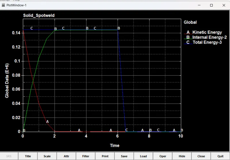
For Solid Elements:
For Beam Elements:
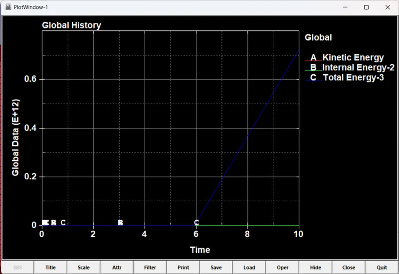
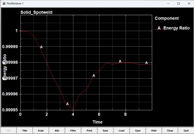
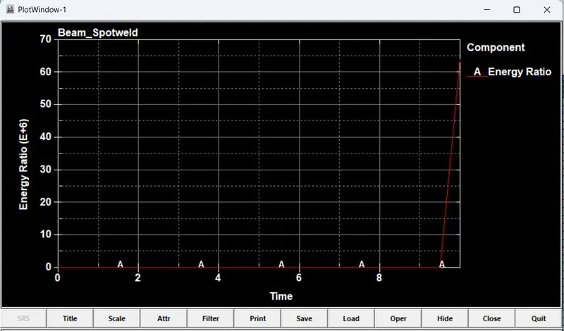
Energy Ratio:
For Solid:
For Beam:
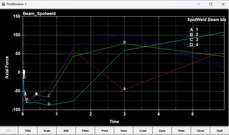
Axial Force:
For Solid:
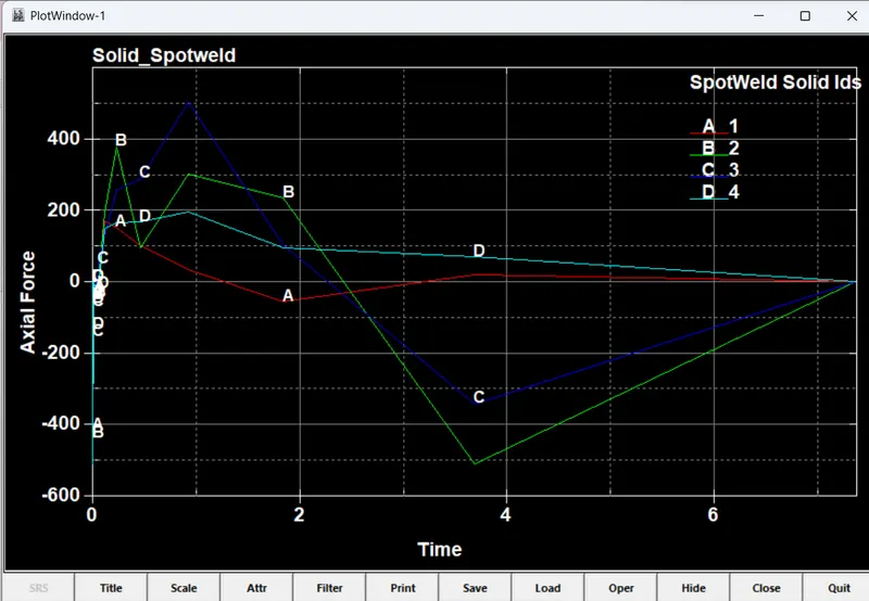
For Beam:
In this, all beam nodes are been compared
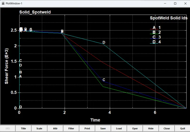
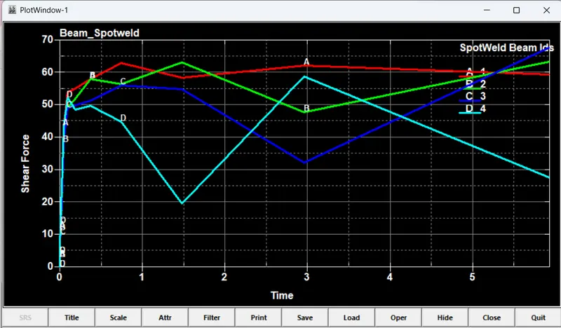
Shear Force:
For Solid:
For Beam Element:
Failures:
For Solid:
For Beam:
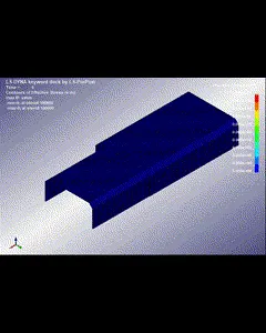
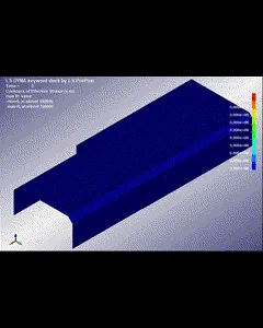
Effective Stress:
For Solid:
For Beam:
Conclusion:
- When a beam element is used for a spotweld, the axial load is higher than normal which may lead to earlier failure if force-based failure criteria are used.
- And, due to the high axial load in the beam element localized stress is also higher. so solid element is more suitable to model the spotweld it has 4 nodes in contact and has better axial and shear capabilities.
- The 3D solid element is more suited to represent spotweld better than the 1D beam element.
- As the Beam element is compared to a Solid it has lower strength, in the Solid element, all 4 nodes are been connected into a single point which makes COG of the element at the center, whereas in the beam element, we have multi interpolation in it.