Week - 5 - Modelling Spotwelds
AIM
Model 3 or 7 spot welds in symmetrical manners for the assembly parts and run a crash test. Spot welds are modeled by using both beam and solid elements. The axial and shear force should be compared among beam and solid elements. The same material card is used for both beam and solid spotwelds. The best simulation should have a failure at half of termination time.
OBJECTIVE
- Modelling spot welds both ways beam and solid.
- Comparison between axial, shear force for both ways of spotwelds.
THEORY
Welding: The welding is a process in which two metals and non-metals or metals nonmetals are joined together.
Types of welding
- GAS welding
- ARC welding
- RESISTANCE welding
- ENERGY BEAM welding
- SOLID STATE welding
Spot welding is a type of resistance welding where a electric current is produced through the resistance provided by the material. This type of welding is mainly use in sheet metal components having thickness less than 3mm.In spot weld two copper alloy electrodes are used into a small spot for holding metals, after this a large amount of electric energy is transferred at the spot to melts the metal and form weld. Welding times ranges from 0.01 sec to 0.63 sec.
PROCEDURES
- Modeling of spot welding for the parts.
ELEMENT TOOL > ELEMENT EDITING
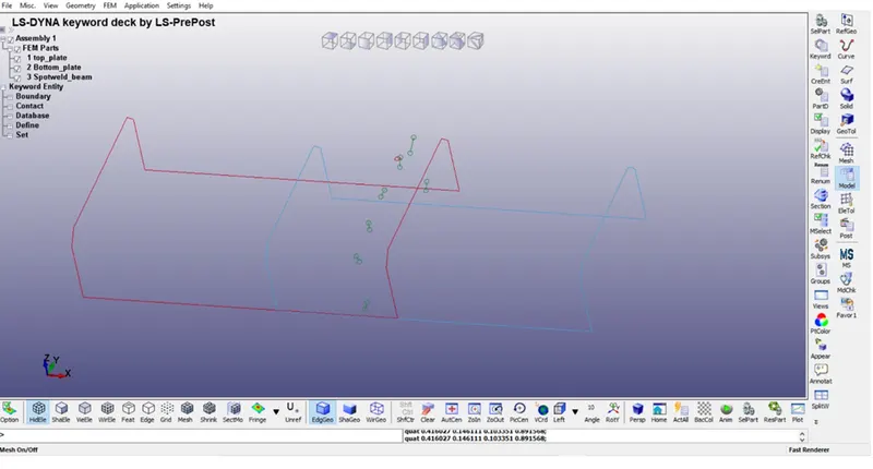
- Section should be defined for physical properties of spotwelds and parts.
KEYWORD > SECTION > SHELL (For Plates)
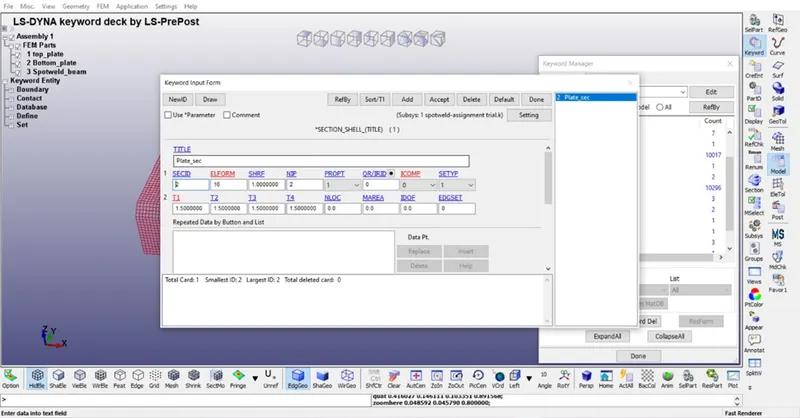
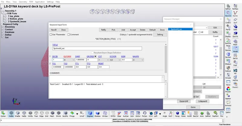
KEYWORD > SECTION > BEAM (For spotwelds)
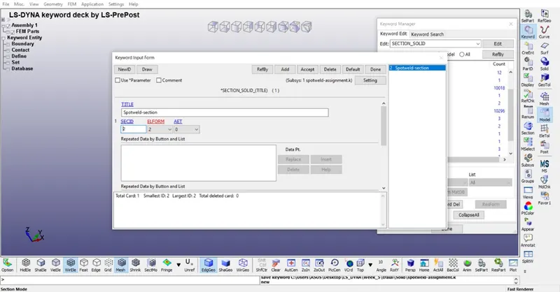
KEYWORD > SECTION > SOLID (For spot welds)
- Material should be defined for plates and spotwelds.
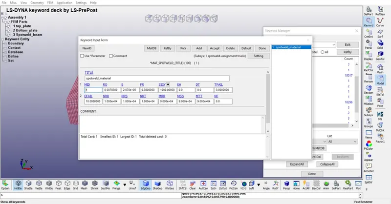
KEYWORD > MAT > 100-SPOTWELDS (For spotwelds)
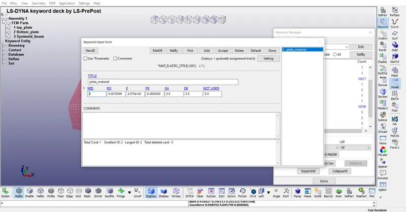
KEYWORD > MAT > 001-Elastic (For plates)
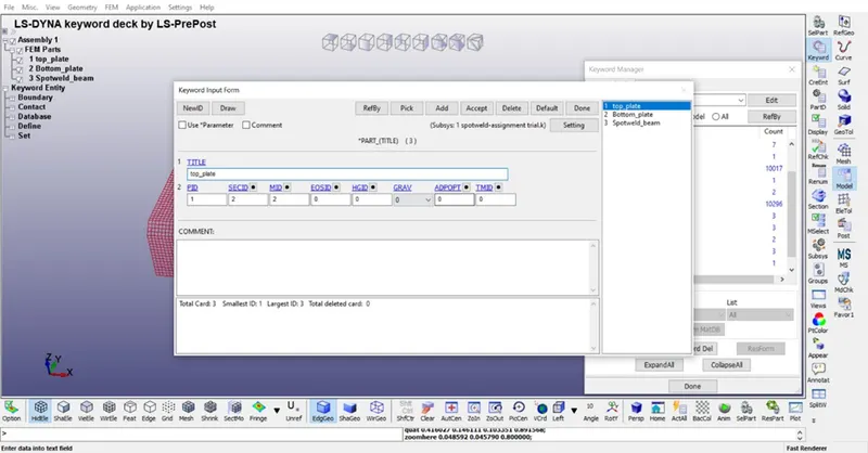
- Now the material and section should be provided an interlink.
KEYWORD > PART > PLATES
KEYWORD > PART > SPOTWELDS
- Now boundary conditions need to defined for simulation.
KEYWORD > BOUNDARY > SPC SET
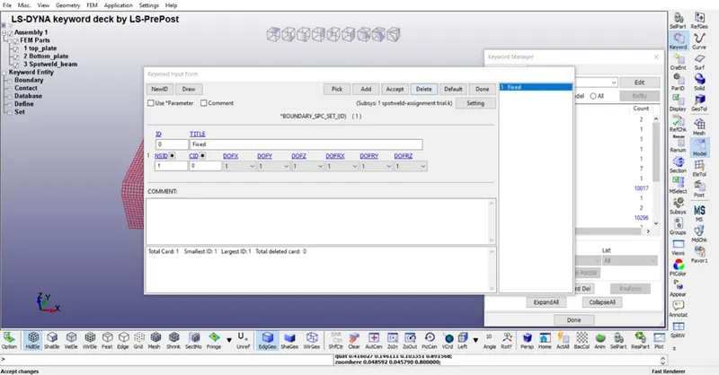
For this Single point constrained set of nodes is need to be defined.
CREATE ENTITY > SET NODES >
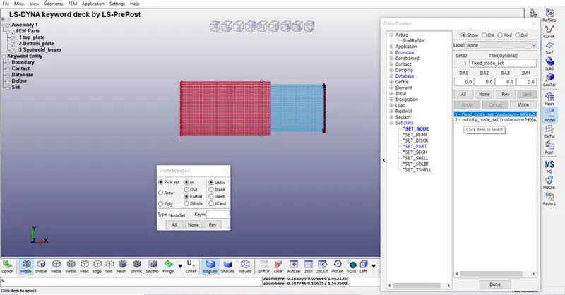
KEYWORD > BOUNDARY > PRESCRIBED MOTION SET
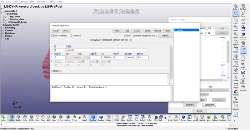
For this also we need to define a set of nodes.
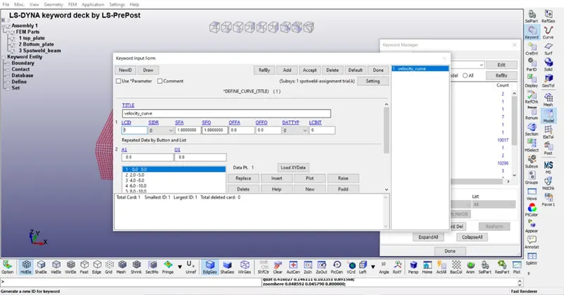
Also a velocity curve is need to be defined
DEFINE > CURVE
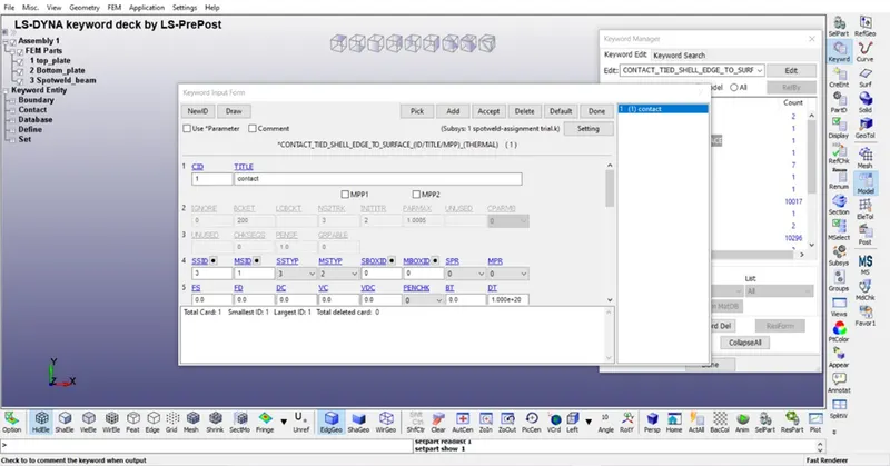
- Contact should be defined cause both plates are welded with spotwelds.
CONTACT > TIED SHELL EDGE TO SURFACE
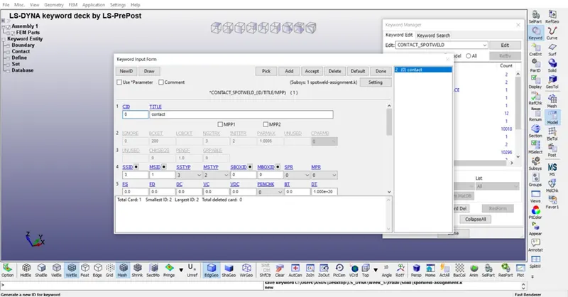
For solid spotwelds different contacts need to be defined
KEYWORD > AUTOMATIC SINGLE SURFACE
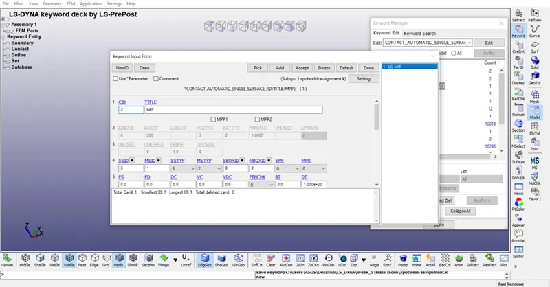
KEYWORD > SPOTWELD
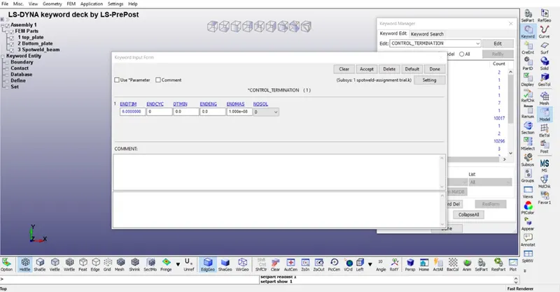
- Termination time should be defined for telling the computer on what time the simulation should be stopped.
CONTROL > TERMINATION
- Now finally the output is defined so that the desired output is collected.
DATABASE > ASCII > GLSTAT, MATSUM, NODOUT, SWFORCE
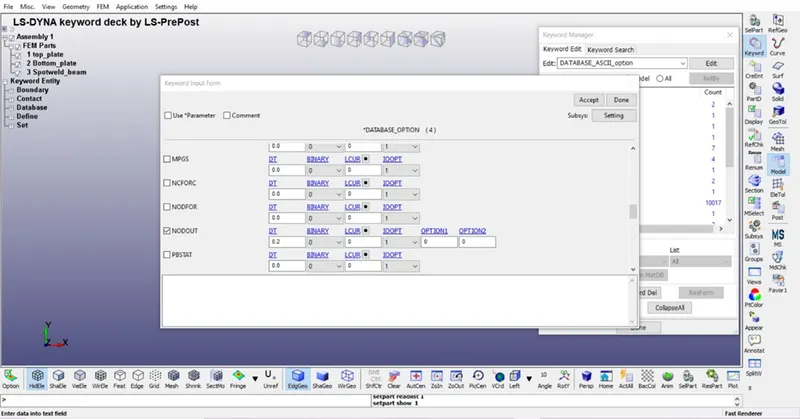
DATABASE > BINARY D3PLOT
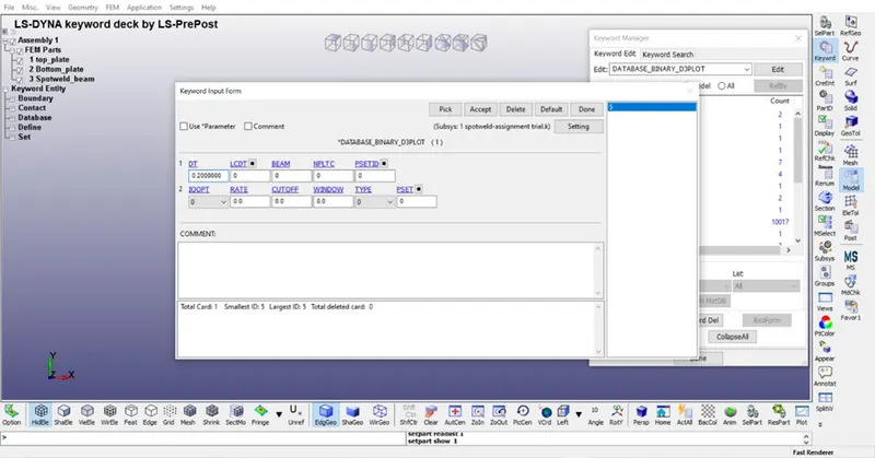
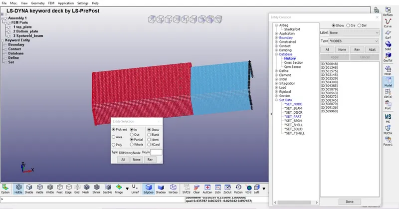
Also, one more thing need to be defined is history nodes. In this different node is selected for the results of NODOUT command.
CREATE ENTITY > DATABASE > HISTORY
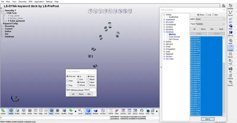
For solid spotwelds different nodes need to be selected.
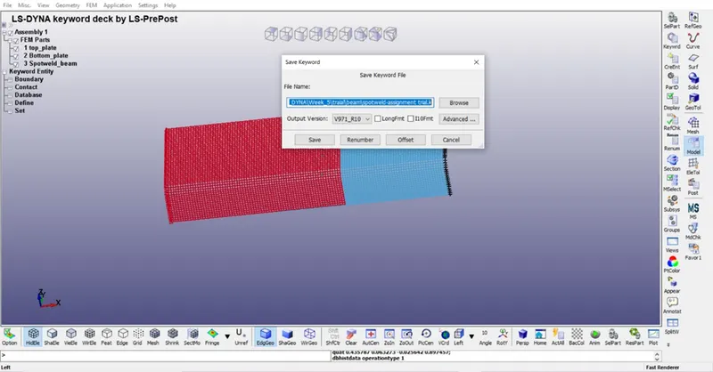
- Now finally all the inputs is being defined and its time for the saving the file.
FILE > SAVE AS > SAVE KEYWORD AS
- Now running the .k file.
FILE > RUN Ls Dyna
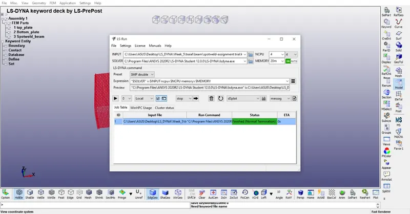
- After running the simulation the binary file should be opened for results.
FILE > OPEN > LS DYNA BINARY PLOT or press CTRL+B
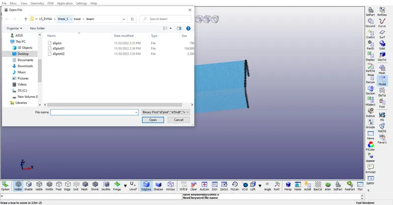
- Now the output file is obtained so that simulation is runed and results can be collected.
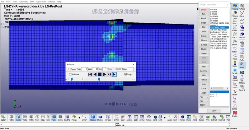
OUTPUTS
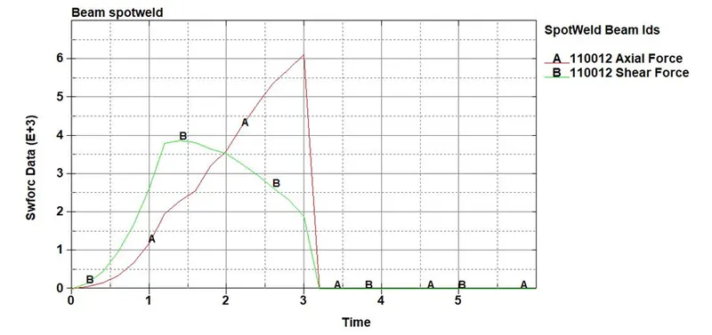
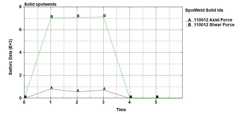
In spotwelds axial force and shear force is compared for both beam spot welds and solid spotwelds
|
Force/Spotweld |
Axial Force |
Shear Force |
|
Beam Spotweld |
6E+3 |
3.8E+3 |
|
Solid Spotweld |
0.9E+3 |
7E+3 |
CONCLUSION
Here from results it is observed that beam element spotweld are strong at axial force and weak in shear force however solid spotweld are weak in axial force and strong in shear force.