Week - 5 - Modelling Spotwelds
SPOTWELD MODELLING IN LS-DYNA
OBJECTIVES:
To perform the crash analysis for beam and solid element spotwelded models and compare the results for the outputs.
PROCEDURE:
1. Import the spotweld.k file into LS-dyna prepost.
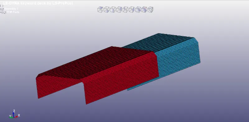
The spotwelds can be modelled as beams and solid elements using LS-Dyna.
a. Beam element with tied shell edge to surface as contact.
b. Solid element with spotweld as contact
c. Using Constrained > Spotweld.
d. Using Constrained > generalized weld.
2. Create a rigid wall using create entity module, so that the component crashes against the rigid wall during approximately 5ms of simulation.
3. Set initial velocity as 10mm/ms for the entire part along Vx.
4. Set Material_Elastic as Steel and give relevant values.
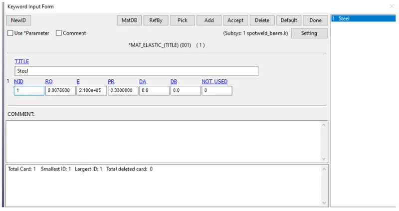
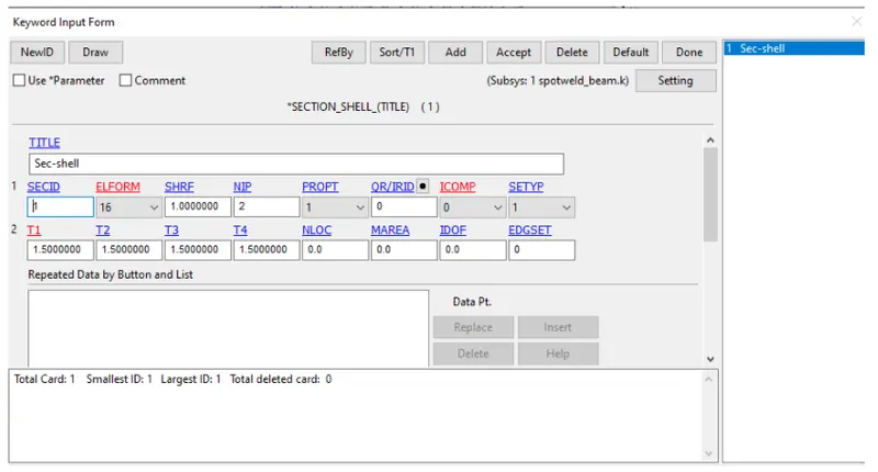
5. Create a section keyword for shell.
6. Create Control termination keyword for 10ms and control energy keyword.
7. Create Database > ASCII, select GLSTAT, MATSUM, SLEOUT, NODOUT, SECFORC, SWFORC with DT=1. Create Database > Binary D3plot > DT = 0.5. Also Create Entity > Database > cross section, select the head and tail node.
8. Renumber the nodes in the area where spotwelds are to be placed to identify them easily. Give start number as 500 and select all the nodes at that cross section.
A. CREATING SPOTWELDS USING BEAM ELEMENT WITH TIED_SHELL_EDGE_TO_SURFACE CONTACT
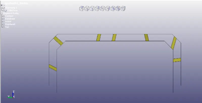
1. Go to Mesh module > Element Generation > Beam > set part as 3 for all the 7 beam elements and select the nodes.
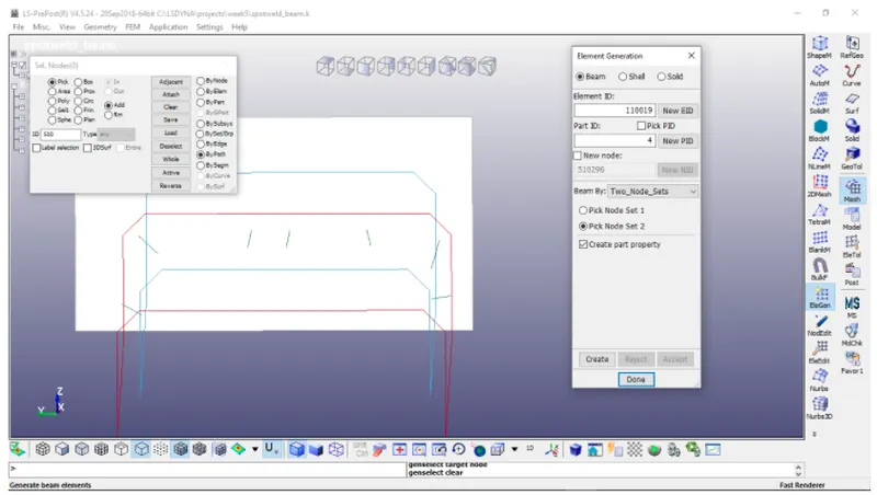
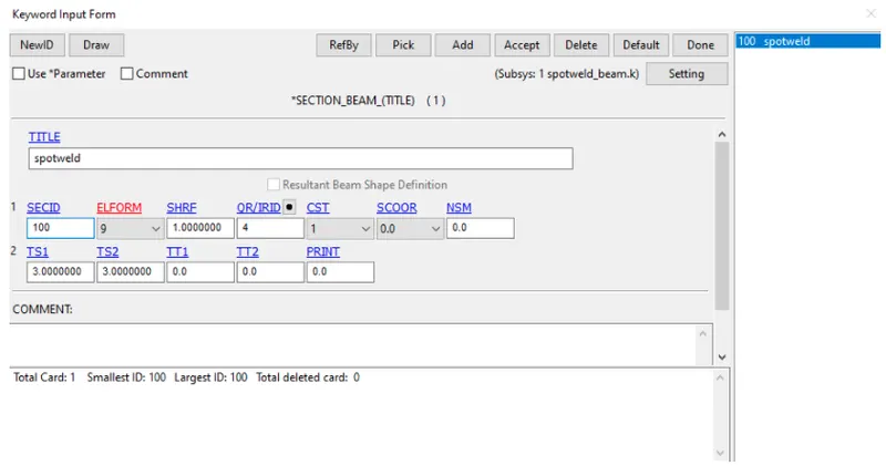
2. Create a Section for beam and enter the values.
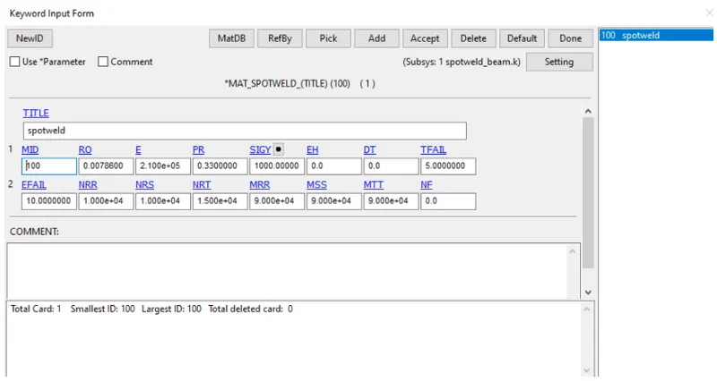
3. Create a material for Spotweld (100) and enter parameters so that the material fails at 5 ms of the simulation time. Assign the material ID and section ID for spotweld part.
4. Create Database > History_beam and select all the 7 beams and in History_node select all 14 nodes.
5. Create Contact > Automatic_single_surface and assign parts as slave by creating a partset. Create Contact > tied_shell_edge_to_surface select the nodes of spotweld beam as slave and partset as master. Check for error using model checker.
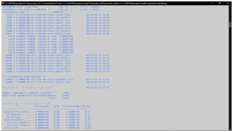
6. Run the simulation after saving as spotweld_beam.k.
B. CREATING SPOTWELDS USING SOLID ELEMENT
1. Go to Element tools module > Element Edit > Create > Hexa set part as 4 for all the 7 solid elements and select the 8 nodes simultaneously to generate each solid element in the areas where previous beam elements were present and delete them. Delete the contact keywords.
2. Create a section for solid. Assign the same Mat_spotweld(100) ID and section ID to the part 4(spotweld_solid).
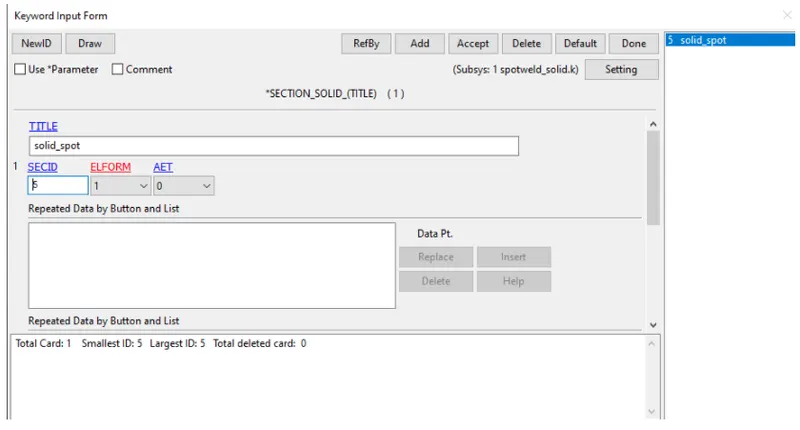
3. Create Contact_Spotweld and assign the 8 nodes of each solid spotweld as slaves and the partset as master.
4. Create History_solid Database keyword and select the 7 solid spotweld elements. Edit the History node and insert the nodes of all nodes associated with the solid elements and select done.
5. Run the simulation after saving the file as spotweld_solid.k.
COMPARING BEAM AND SOLID SPOTWELD MODELS:
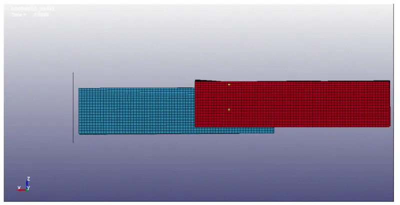
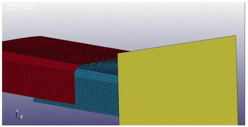
In both the simulation the component hits the rigid wall at 5ms of the simulation, the spotweld fails, exactly half the termination time. There is no abnormal behaviour of elements during the simulation.
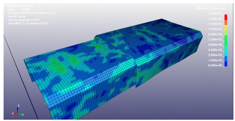
1. Vonmisses Stress:
Max Vonmisses stress for spotweld_beam: 3020 MPa
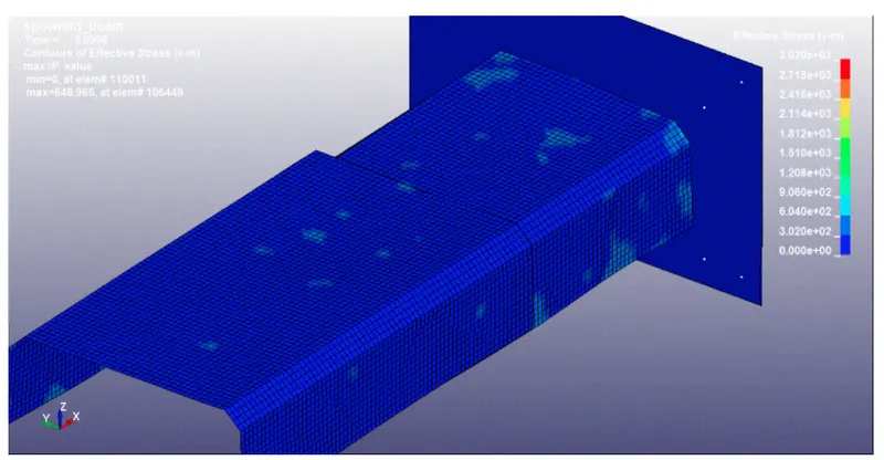
Max Vonmisses stress for spotweld_solid : 1450 MPa
ENERGY GRAPH:
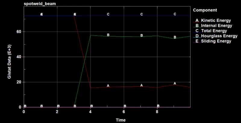
The Total Energy of the beam spotwelded component is at 72 KJ. When component hits the rigid wall, the the kinetic energy reduces to 15KJ and internal energy increases to 58 KJ. There is no Hourglass energy since fully intergrated elements are used and the sliding energy is negligible so the simulation is acceptable.
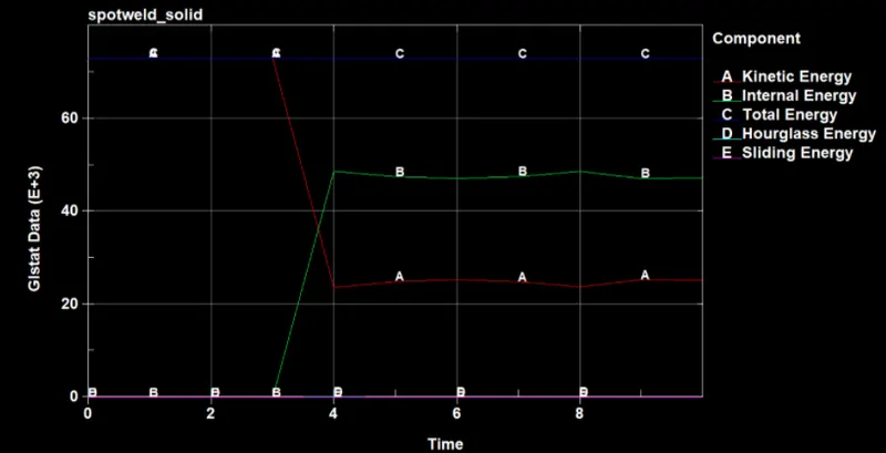
The Total Energy of the solid spotwelded component is at 72 KJ. When component hits the rigid wall, the the kinetic energy reduces to 23KJ and internal energy increases to 48 KJ. There is no Hourglass energy since fully intergrated elements are used and the sliding energy is negligible so the simulation is acceptable.
3. ACCELERATION GRAPH:
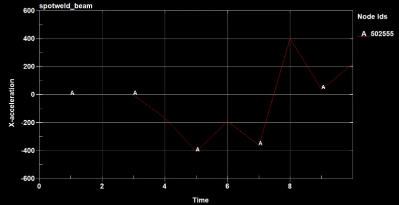
Max acceleration = 400mm/ms2, max deceleration = 400 mm/ms2 for beam spotwelded component.
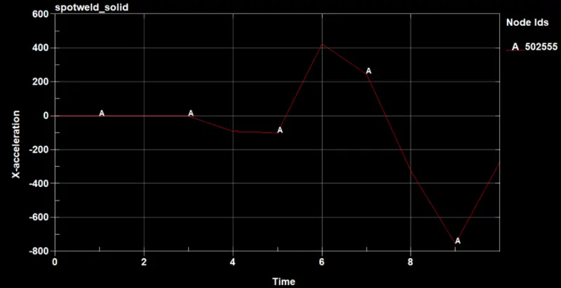
Max acceleration = 410mm/ms2, max deceleration = 780 mm/ms2 for solid spotwelded component.
SPOTWELD MODEL ACCELERATION on node 502555 DECELERATION on node 502555
BEAM 400 mm/ms2 400 mm/ms2
SOLID 410 mm/ms2 780 mm/ms2
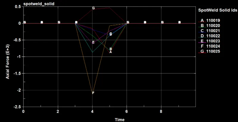
4. AXIAL FORCE FOR SPOTWELD:
BEAM : Max force 2.5 KN on beam element 110016.
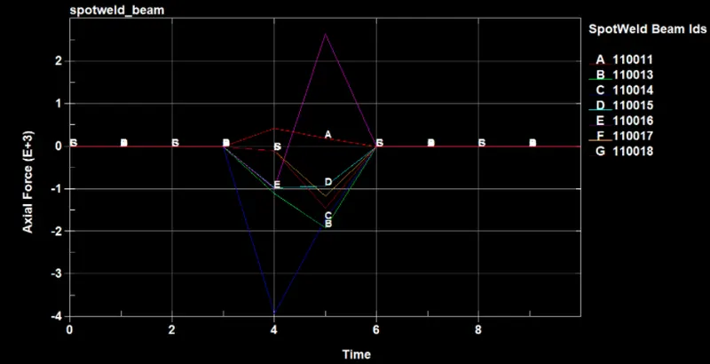
Solid : Maximumum Force = 0.5 KN for 110025 solid element.
5. SHEAR FORCE:
BEAM : Max force = 2.7 KN
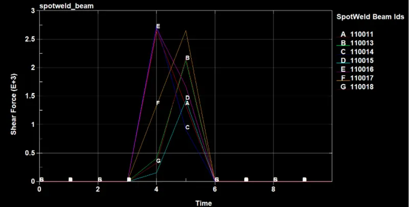
Solid : Max force = 3.8 KN
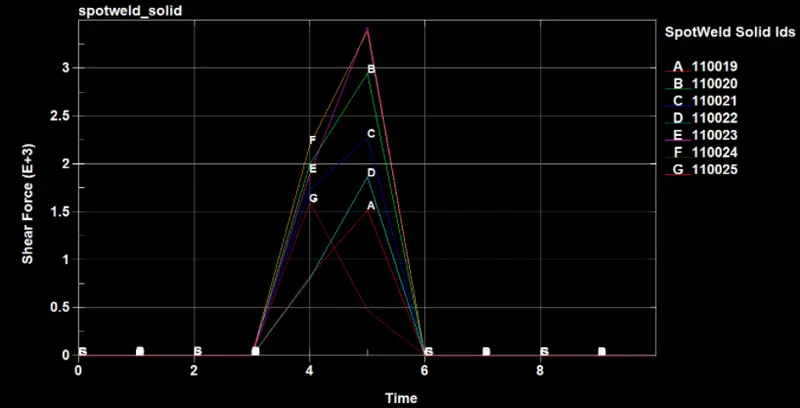
SPOTWELD MODEL AXIAL FORCE SHEAR FORCE
BEAM 2.5 KN 2.7 KN
SOLID 0.5 KN 3.8 KN
6. Cross section force:
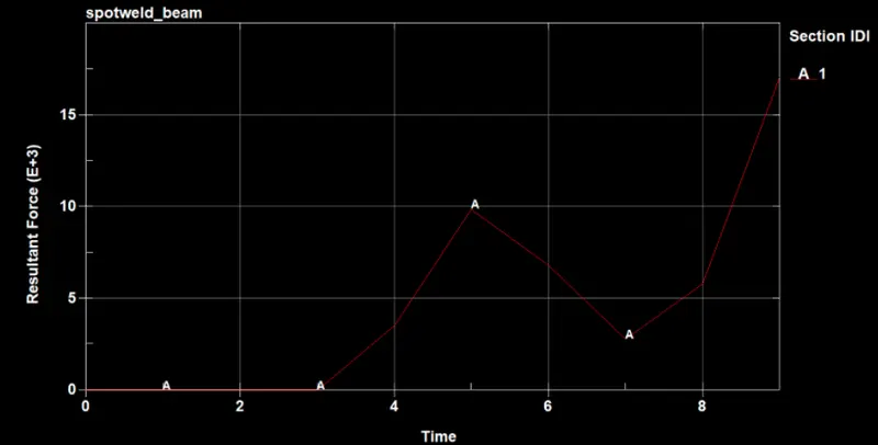
At 5 ms, the resultant force at cross section on the middle of beam spotwelded component is 10 KN.
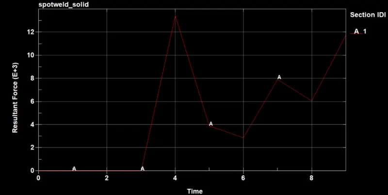
At 5 ms, the resultant force at cross section on the middle of solid spotwelded component is 4 KN.
SPOTWELD MODEL CROSS SECTION FORCE
BEAM 10 KN
SOLID 4 KN
7. Maximum Directional Stress and Strain
Spotweld X-stress y-stress X-strain y-strain
Beam 2119 MPa 1453 MPa 1.358e-3 1.700e-3
Solid 1491 MPa 785 MPa 1.194e-3 1.272e-4
"Hence from the above comaprison, the solid element play a greater role in the analysis, as they show reasonable stress-strain results when compared to beam elements in spotweld modelling. The cross sectioinal forces are greater beacause the solid adds stiffness to the component. The axial forces acts low in the solid element and shear forces are detected very well while the internal energy is lower after failiure."
CONCLUSION:
1. The spotwelds are modelled using Beam and Solid elements for same component.
2. Respective contacts and Database keywords are assigned.
3. The plot results and contour diagrams are compared.