Week 4-1D Element Creation Challenge
AIM : to form ID components on the subsequent part with given cross-sectional and DOF.
OBJECTIVE :
a.Rod element:- with solely translational DOF and RBE2 link
Cross-Section: BOX- Dimension a= twelve millimeter
dimension b=10 mm
Thickness t= zero.75 mm
b. Beam element:- with all DOF and RBE3 link
Cross-Section: I Section- Dimension a= 8mm
Dimension b= 10mm
Dimension c= 8.5mm
Thickness tl= 0.75 mm
Thickness t2= .6 mm
Thickness t3= .6 mm
C.Bar element:- with solely x and y DOFs With RBE3 link
Cross-section: CROSS section- Dimension DIM1= 5mm
Thickness DIM2= 1.2 mm
Dimension DIM3= 10mm
Thickness DIM4= 1.2mm
d& e. apply the mass of magnitude ten with RBE2 link
f. join the two components with Spring elements
THEORY :
RBE2 Panel :
A rigid part is part created during a area between 2 nodes of a model wherever a rigid affiliation is desired. within the RBE2 link, Load are distributed equally for all nodes.
Rigid link components may be created with dependent nodes connected to part as a group. If a rigid link with a dependent node-set is deleted, the associated node-set is additionally deleted. If the dependent node-set in any panel is deleted, the connected rigid link part is additionally deleted. Dependent node sets square measure mechanically created once rigid link components square measure created. A node-set created within the Sets panel may be connected as a group of dependent nodes to a rigid link part freelance node.
RBE3 Panel
RBE3s square measure interpolation constraint components, wherever the motion of a dependent node is outlined because the weighted average of the motions of a bunch of freelance nodes. The dependent degrees of freedom and coefficient factors may be nominative or mechanically calculated supported the pure mathematics.
RBE3s square measure generally accustomed distribute masses applied to the dependent node amongst the chosen freelance nodes. within the RBE3 link, Load distribution are varied.
Masses Panel :
Use the lots panel to form mass components. A mass part rests on a node and is employed to represent mass.
Rods Panel :
Use the Rods panel to form rod components. A rod part is part created during a area between 2 nodes of a model wherever rod properties square measure desired. the 2 nodes square measure associated with one another supported the properties of the rod part connecting them.
Hyperbeam Panel :
Use the HyperBeam panel to form beam cross-sectional entities that you just will use to change advanced parts of your model into straightforward bar components. The HyperBeam panel is organized into many subpanels. every subpanel covers a special sort of beam section, apart from the a lot of general edit section and section utils (utilities) subpanels. It will move freely between subpanels. performing on one sub panel won't be lost if you turn to a special subpanel.
Springs Panel :
Use the Springs panel to form spring components. A spring part is part created during a area between 2 nodes of a model wherever a spring affiliation is desired.
PROCEDURE :
- Import the given part victimisation the Import choice in Hypermesh.
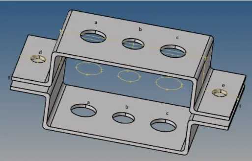
Fig 1: Imported Parallel Bracket Model
2.Creating a Mid-surface of the given part by victimisation Geom-->midsurface choice.
3. Use the extraction choices subpanel to outline Associate in Nursing offset choice to middle surface in extraction settings.
4. Use the automotive vehicle Midsurface subpanel to extract the middle surface of a a lot of sophisticated cluster of surfaces that represent a solid half in one step.
5. Once making a middle surface of the given part, Use Washer Split choice and make a washer as 5mm on every pinhole.
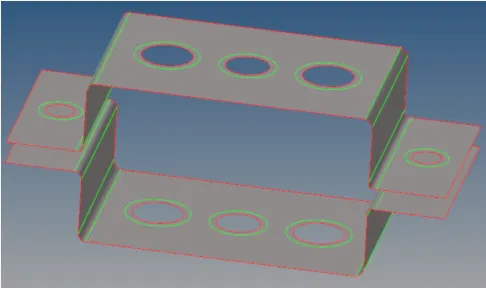
Fig 2 : Midsurface Component
6. Once making a middle surface, visit 2D-->automesh choice and set part size and mesh the part.
7. Whereas meshing, Keep the quantity of components on each side of the half as adequate to avoid tria & quad components.
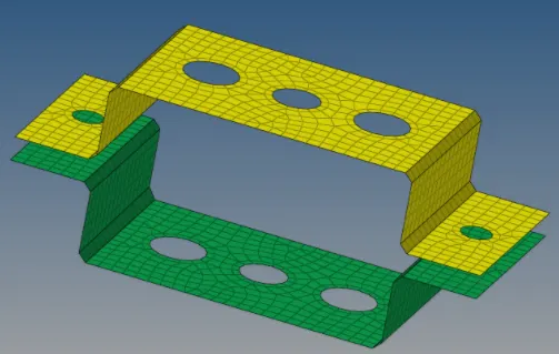
Fig : Mesh Component
8. Produce Steel Material Card & Property Card for the Parallel Bracket one & a pair of by victimisation Model Browser-->Right Click-->Create-->Material & Property choice.
9. Assign the fabric & Property for Bracket 1 & 2 in the Component.
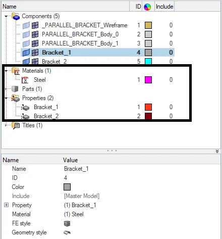
Fig : Created Material & Property
a. Rod part :
10. Making a Rigid body RBE2 link with solely translational DOF during a.
11. Go to 1D-->rigids choice and set as multiple nodes & amp; calculated nodes and choose the sole translational DOF and select the edges and click Create.
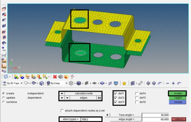
Fig : RBE2 with only translational DOF
12. Go to 1D-->Hyperbeam-->Standard Section and choose kind as thin-walled box and click on produce.
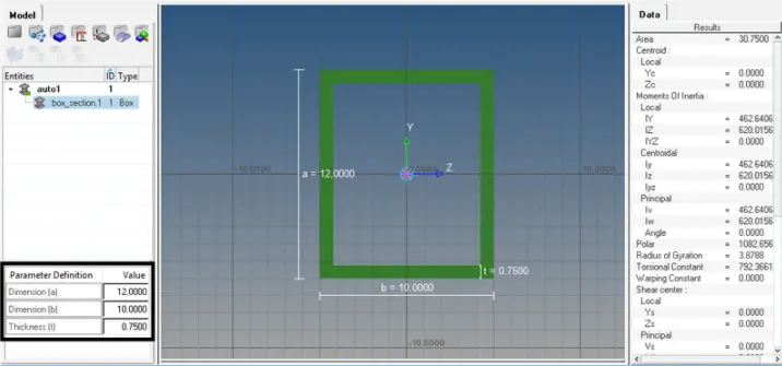
Fig : Box Section
13. Once making Box Section, visit Model Browser and make Property for Rod and choose Beam Section as Box Section.
14. Create a brand new part as Rod and assign the Rod Property to the rod part.
15. Go to 1D-->rods choice and Set Property as Rod and part kind as CROD and choose Master node of 2 rigid body and make it.
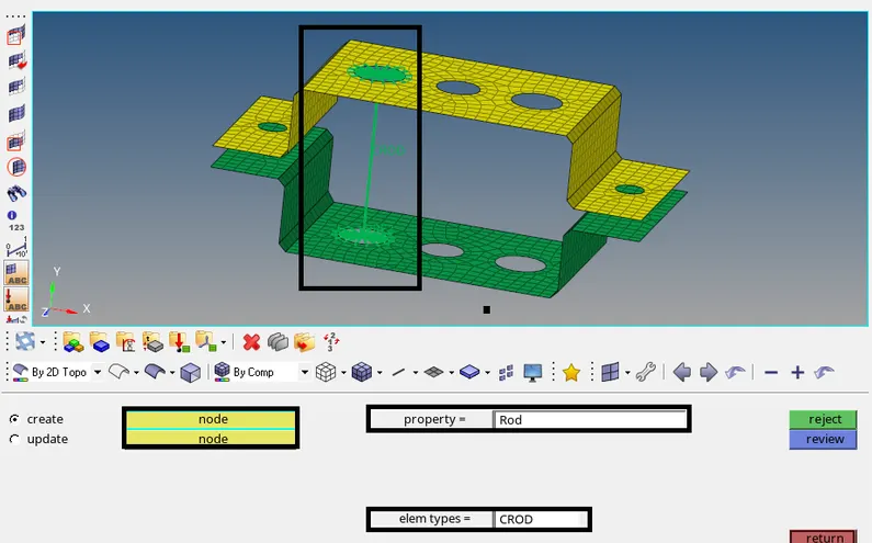
Fig : Rod Element
- Creating a Rigid body RBE3 link with all DOF in b.
- Go to ID-->rigids option and set as multiple node & calculated node and Select all DOF and select the edges and Click Create.
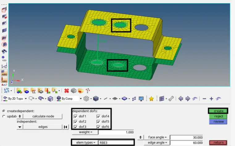
Fig : RBE3 with all DOF
18. After Creating the RBE3 link, Go to Hyperbeam view→ Create → Standard Section → Hypermesh and select type as standard | section and Click Create.
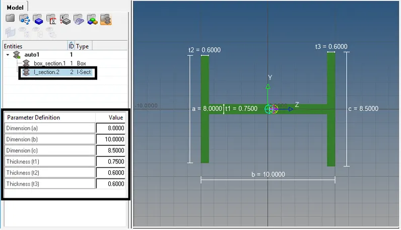
Fig : I Section
19. After Creating I Section, Go to Model Browser and Create Property for Beam and Select Beam Section as I Section.
20. Create a new Component as Beam and assign the Beam Property to the Beam component.
21. Go to ID-->bars option and Set Property as beam and element type as CBEAM and Select Master node of two rigid body and Create it.
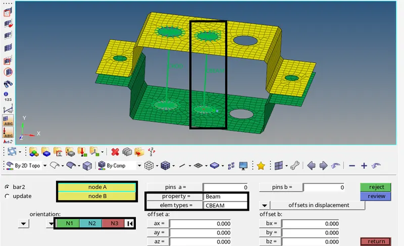
Fig : Beam Element
22. Creating a Rigid body RBE3 link with only x and y DOF in c.
23. Go to 1D→ rigids option and set as multiple node & calculated node and Select only x & Y DOF and select the edges and Click Create.
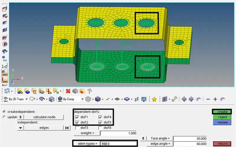
Fig : RBE3 with only x & y DOF
24. After creating the RBE3 link, Go to Hyberbeam view --> Create --> Standard Section --> Optistruct and select type as cross section and click create.
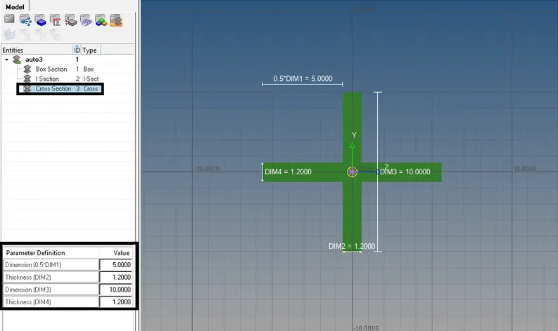
Fig : Cross Section
25. when making Cross Section, attend Model Browser and make Property for Bar and choose Beam Section as Cross Section.
26. produce a brand new element as Bar and assign the Bar Property to the Bar element.
27. attend 1D->bars choice and Set Property as bar and part kind as CBar and choose Master node of 2 rigid body and make it.
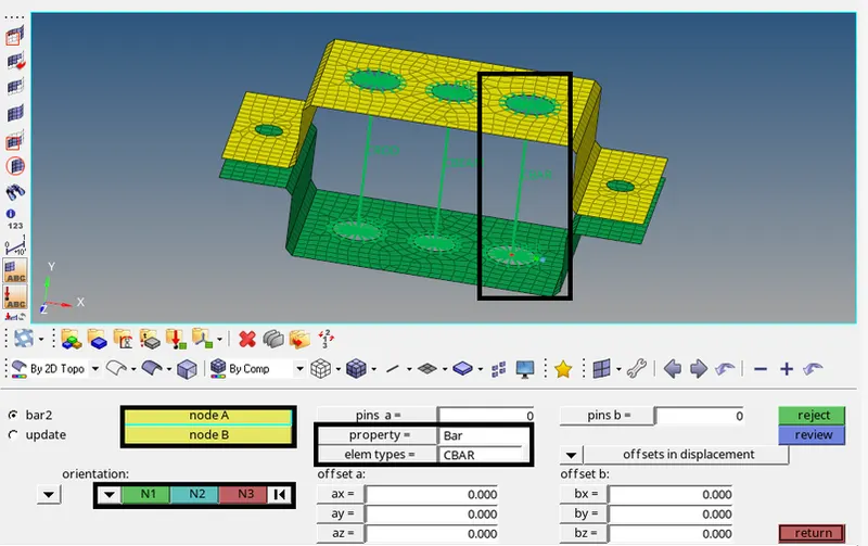
Fig : Bar Element
D&E Add Mass
28. attend attend choice and set as multiple node & calculated node and choose all DOF and choose the sides on 2 sides and click on produce.
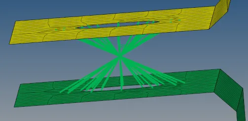
Fig : RBE2 will all DOF
29. when making the RBE2 link, attend Model Browser and make Property for Mass, and choose Material as Steel. 30. produce a brand new element as Mass and assign the Mass Property to the Mass element.
31. attend 1D-->Masses choice and choose RBE2 Master node and Set mass price as ten and Property as Mass and choose elem kind as CMASSI
and Click produce.
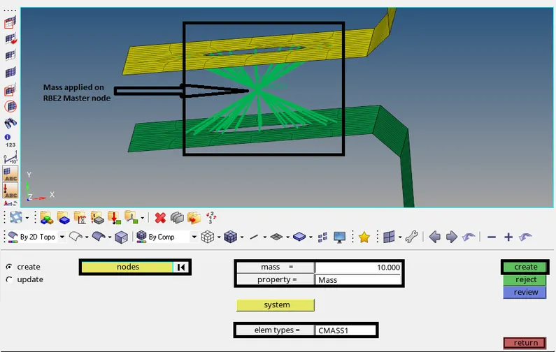
Fig : Added mass with RBE2 link
F.Spring Element
32. attend Model Browser and make Property for Spring, and choose Material as Steel
33. produce a brand new element as Spring and assign the Spring Property to the Spring part.
34. attend 1D-->springs choice and choose the 2 nodes of the parts and Set elem kind as CELAS1 and make a Spring
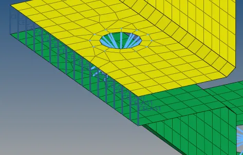
Fig : Create Spring Element
CONCLUSION :
Created 1D elements on the given component with given cross-section and DOF.
a -Rod element Created with only translational DOF and RBE2 link.
b- Beam Element Created with all DOF and RBE3 link.
c-Bar Element Created with only x &Y DOF and RBE3 link.
d&e Mass added on the Master node of RBE2 link.
f-Two Components were joined with Spring Elements.
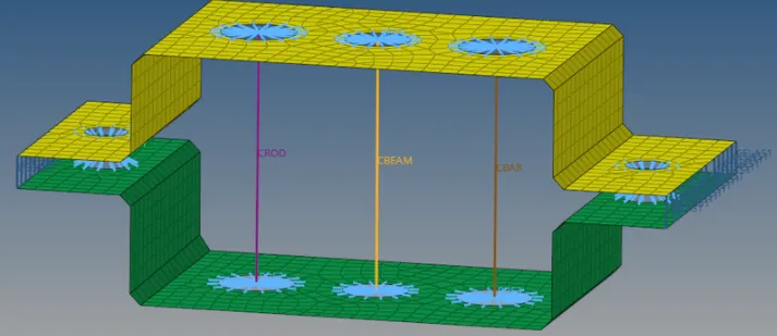
Fig : Traditional Element Representation
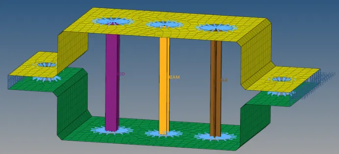
Fig : Detailed Element Representation
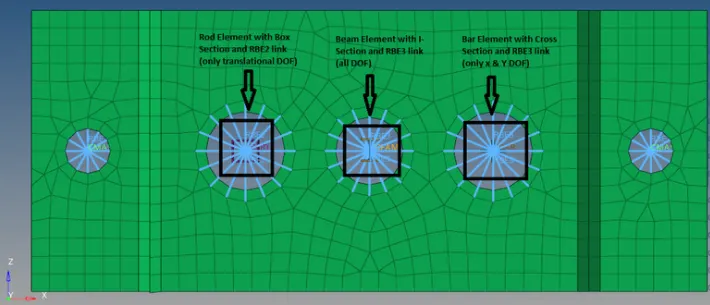
Fig : Top View
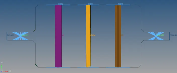
Fig : Front View