Week - 5 - Modelling Spotwelds
Modelling Spotwelds
AIM:
To model spot welds for the given assembly and simulate crash test.
Case 1: Beam_Spot_weld
Case 2: Solid_Spot_weld
OBJECTIVES:
• To define spot welds using beam and solid elements.
• To create a solver deck to perform the crash test simulation.
• To enter the values in g mm ms unit system.
• To assign steel material properties for the crash box and rigidwall for the rigid wall.
• To assign initial velocity for the crash box at 50kmph.
• To create contact card.
• To create control keywords.
• To measure the cross section force generated at the spot weld.
• To plot the total, internal, kinetic, hourglass, sliding energy graphs.
• To compare the results with the beam and solid spot weld elements.
• To run the .K file and evaluate the results.
UNIT SYSTEM USED: G MM MS
BOUNDARY CONDITIONS:
• The crash box should crash onto the rigidwall.
• Material of crash box is Steel and that of weld is Spotweld.
• Initial velocity of crash box is 13.889mm/ms.
MATERIAL PROPERTIES:
• Crash Box:
Density: 0.0078g/mm3
Youngs Modulus (E): 210000g/mm*ms2
Poissons Ratio: 0.3
Yield Strength: 350 g/mm*ms2
INTRODUCTION :
The representation of the spotweld in finite element models has been problamatic for a number of years.
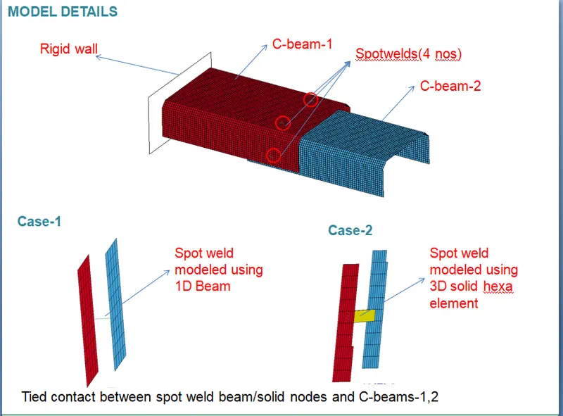
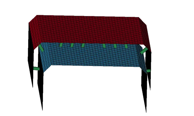
- The simplest representation consists of a rigid link connecting two or more sheets represented with thin shell elements. This method requires the mesh of the different sheets to be aligned, and for complex models, this poses a very difficult logistical problem. This has been addressed by using beam elements using a Tied contact to attatch the beams representing the weld to the sheet.
- Solid hexahedral elements can also be used in the representation of spotwelds. In this paper, the development and the methodology of applying Beam as well as hexahedral element for spotweld in connection to two different sheets will be presented, which leads to successful application of weld failure.
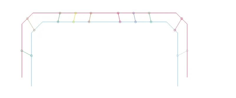
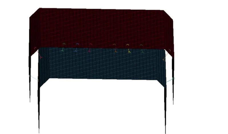
- beam element
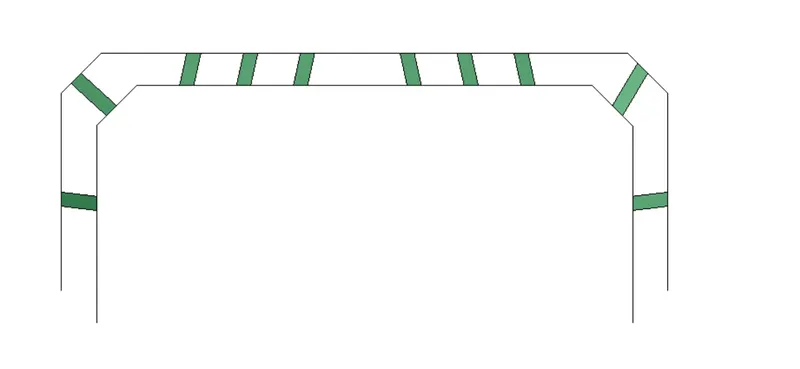
- solid element
PROCEDURE :
1. Importing:
FILE > OPEN > LS DYNA KEYWORD FILE > SPOTWELD_ASSIGNMENT.
Then, go to MODEL AND PART COMMAND > KEYWORD MANAGER.
We can check the keywords in the model.
2. Part Check:
Go to MODEL AND PART COMMAND > PART DATA. We can see that the model consists of 2 part i.e. top and bottom layer.
Now, rename the parts as top and bottom layer.
Now, in the part card we have to define section and material, so let’s create a Section and Material card.
3. Beam_Spotweld:
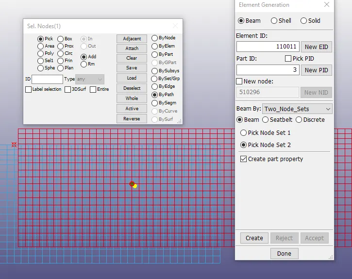
• Go to MESH > ELEMENT GENERATION > BEAM > BY TWO_NODE_SETS > SELECT THE 1ST NODE > SELECT THE 2ND NODE > CREATE > DONE.
4. Section for shell and beam element:
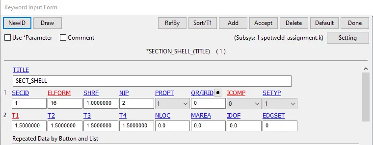
Go to MODEL AND PART COMMAND > KEYWORD MANAGER > ALL > SECTION > SHELL > TITLE = SECT_SHELL > SECID = 1 > T1 = 1.5 > ACCEPT > DONE.
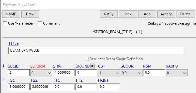
Go to MODEL AND PART COMMAND > KEYWORD MANAGER > ALL > SECTION > BEAM > TITLE = BEAM_SPOTWELD > SECID = 2 > ELEMFORM = 9 > QR/IRID = 4 > T1 = 3 > ACCEPT > DONE.
5. Material for shell and beam element :
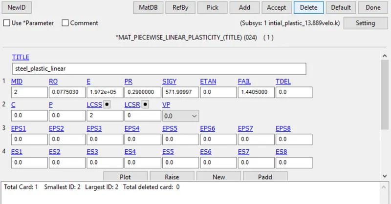
plastic behaviour using the MAT_24 card
first define the curve between effective plastic strain and effective stress
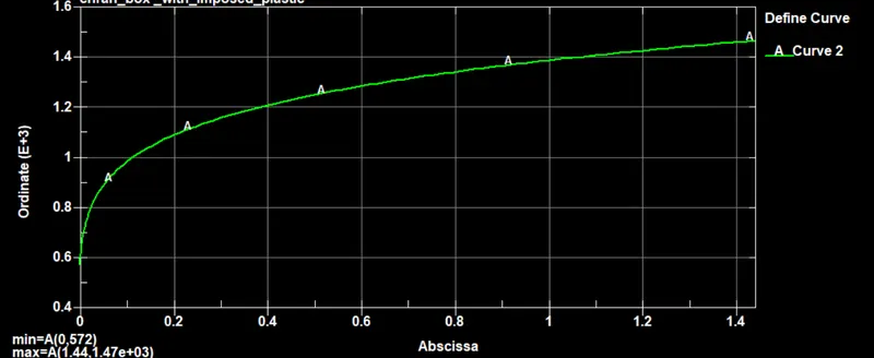
link this curve in the MAT_24 byLCSS
Several failure models have been developed and implemented in the widely used LS -DYNA software topredict spot-weld failure during crash simulations. *MAT_100_DA is one of such models and has been used in the current study
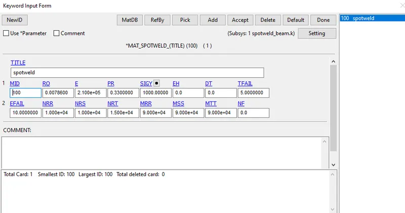
The Nrr, Mrs, Mrt, Nrs and Nrt values are maximum spot-weld force and moments prior to failure, which are generated from the experimental tests performed on coupon level in different loading modes , such as Tension-Shear (TS), Coach-Peel, (CP) and KSII configurations
6. define rigid wall :
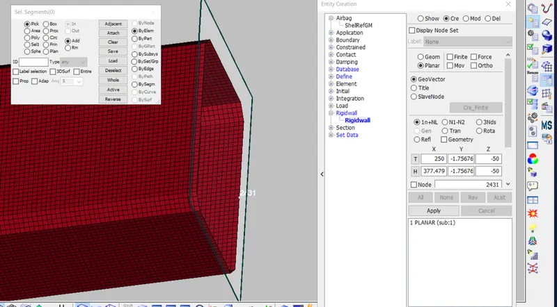
after creation of the rigid wall it is required to translate the rigid wall
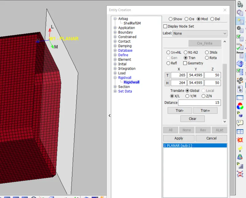
normal vector of the rigid wall plane should be in direction of the body as shown below otherwise it will not treat contact between wall and box
6. define initial velocity :
50kmph =13.889 mm-ms
define the node set for which velocity should applied
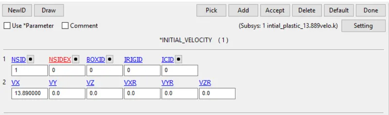
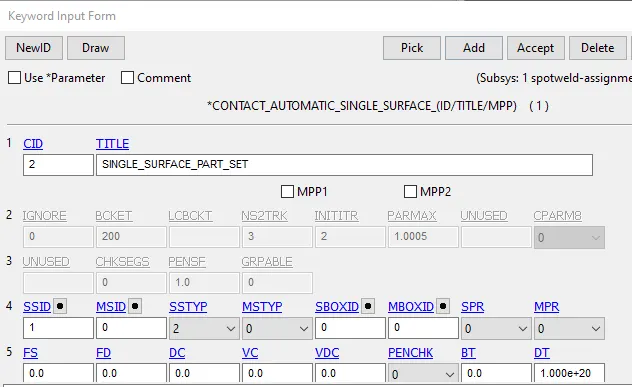
7. defininig the contact :
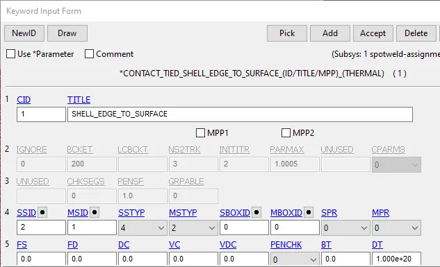
in this model two type of contact is defined
1. Automatic_Single_Surface
2. TIED_EDGE_SHELL_TO_SURFACE
8. assigning the section and material for the part
After defining the material and section for shell element and weld element then it must be linked with part, which is done by selecting the appropriate section and material from defined section and material list in part keyword
9. control termination and output request :
- in this model i requested the ASCII : glstat, matsum, swforce , rcforce , elout ,ndout and D3PLOT,
- define the time period for simulation using the control termination.
SOLID SPOT-WELD ELEMENT CREATION
the above 9 steps are necessary for spot weld beam element but if we want to use the solid weld ement then remove the beam weld and define the solid weld as step show below
1. Open the BEAM_SPOTWELD K file and delete the beam elements.
2. Go to Element tools module > Element Edit > Create > Hexa set part as 4 for all the 10 solid elements and select the 8 nodes simultaneously to generate each solid element in the areas where previous beam elements were present and delete them. Delete the contact keywords.
3. Create Contact_Spotweld and assign the 8 nodes of each solid spotweld as slaves and the partset as master.
4. Create a section for solid. Assign the same Mat_spotweld(100) ID and section ID to the part 4 (spotweld_solid).
RESULT :-
BEAM SPOT WELD
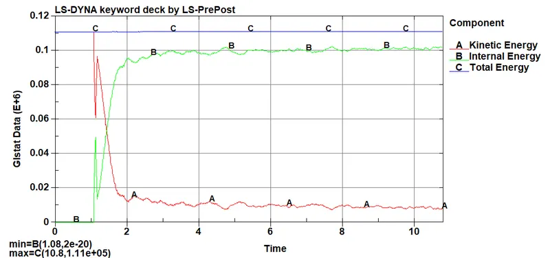
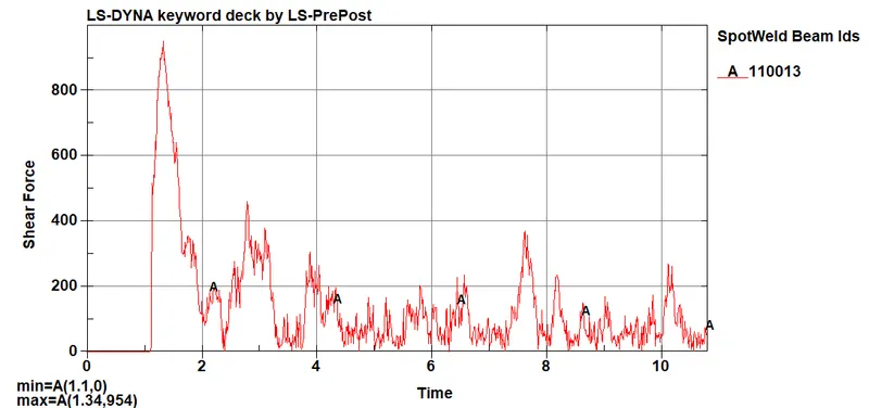
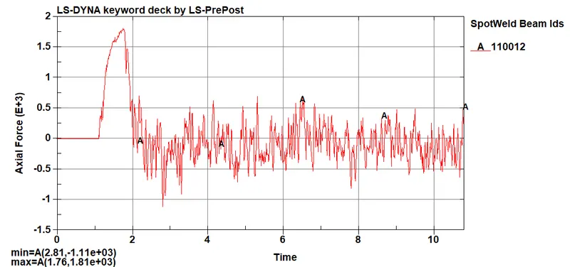
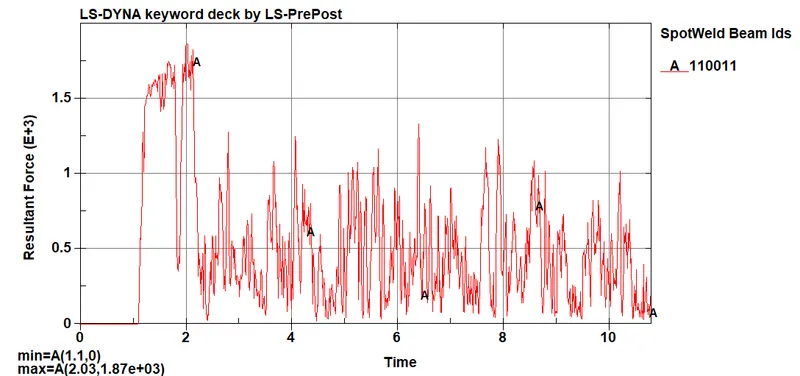
SOLID SPOT WELD
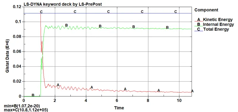
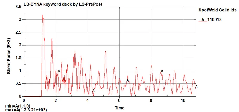
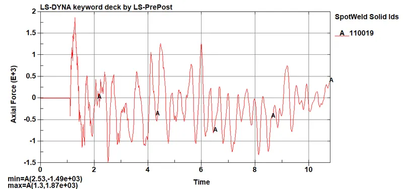
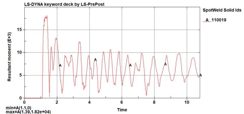
From the above plots,
- From overall results, we can conclude that Solid elements are more robust and can give more accurate results and are more preferable. Though in some cases, where only axial forces are more important, or for more faster results, Beam elements can be used.
- When we have no accurate or standard data for the Axial & Shear forces at failure, than we can use the Time dependent failure to get the results at which the Spotwelds are failing, and for that we have to run the simulation for more longer time dependent failure or we can also use plastic strain failure also.
LEARNING OUTCOMES:
• To import the Keyword file.
• To check the model for parts data and keyword manager.
• To assign keywords for the model.
• To create beam and solid spotweld elements.
• To define section and material properties for the parts.
• To define rigid wall.
• To define boundary conditions.
• To define initial velocity.
• To define the output results.