Week - 5 - Modelling Spotwelds
AIM :
To simulate the spot weld joint component by using the LS-Dyna.
PROCEDURE :
1. Import the model in the .k file in LS-Pre post.
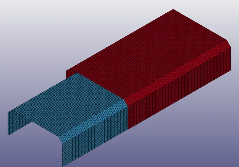
2. Create the Material and sections for components as shown below.
MATERIAL :
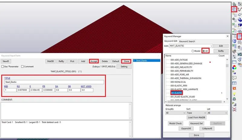
SECTION :
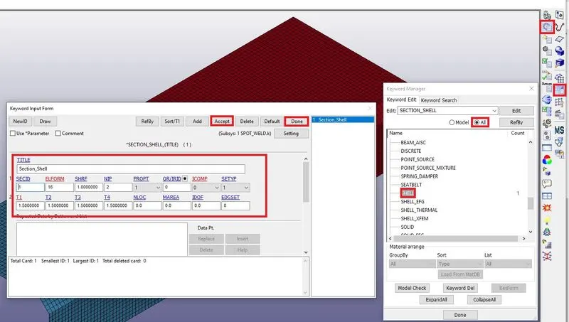
3. Assign the section and material to the components as shown below.
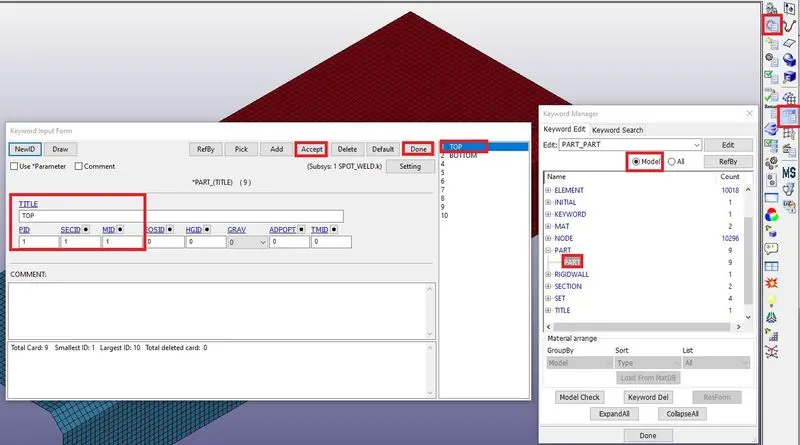
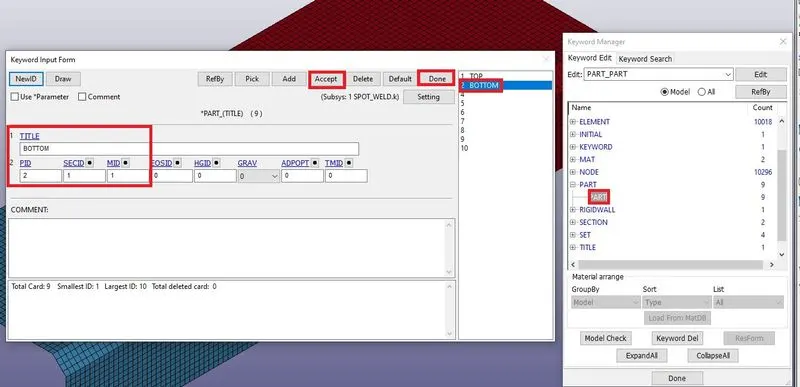
4. Create the spot weld beam elements to both components as shown below.
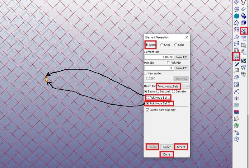
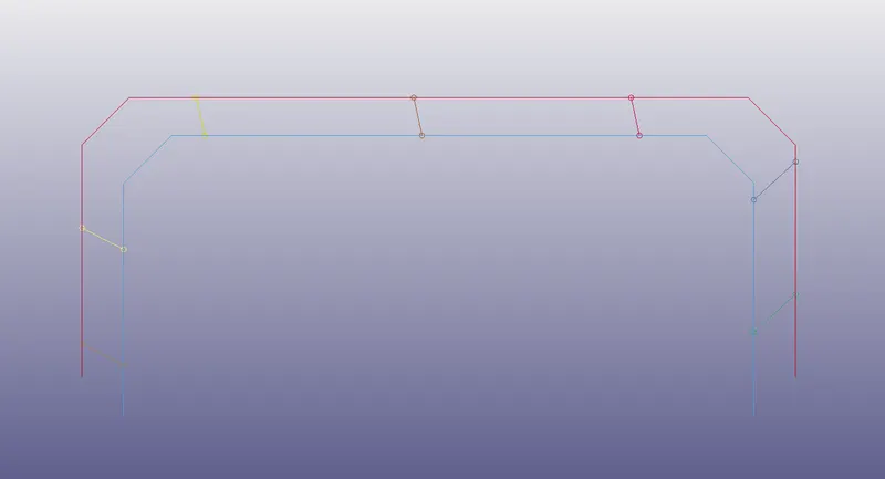
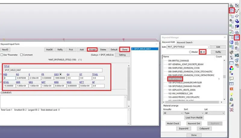
5. Create spot weld material and Beam section as shown below.
Spot weld material :
Section beam :
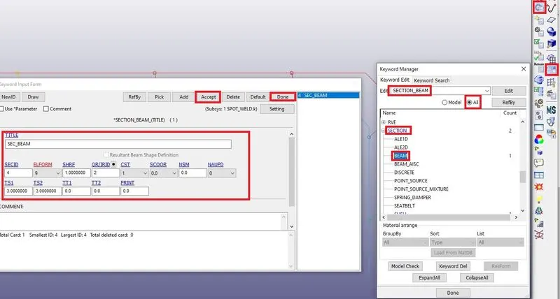
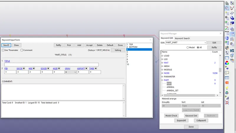
6. Assign the section and spot weld material to the beam elements as shown below.
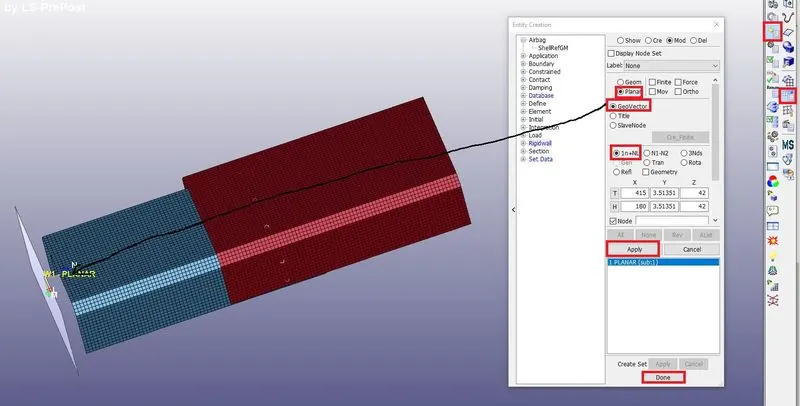
7. Next create the Rigid wall to the component as shown below.
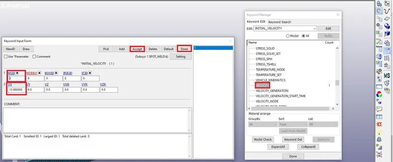
8. Next give the velocity to the component as shown below.
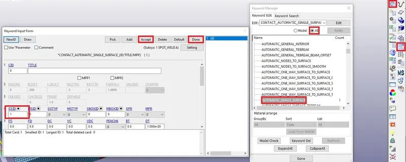
9. Create the contact automatic single surface as shown below.
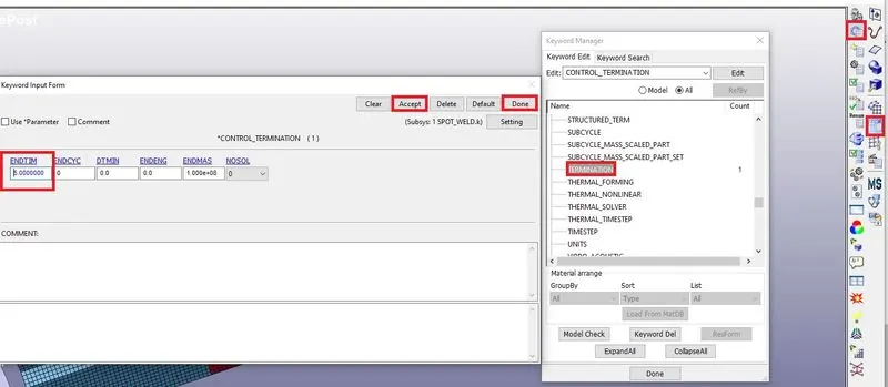
10. Create the Control termination as shown below.
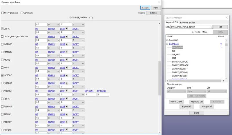
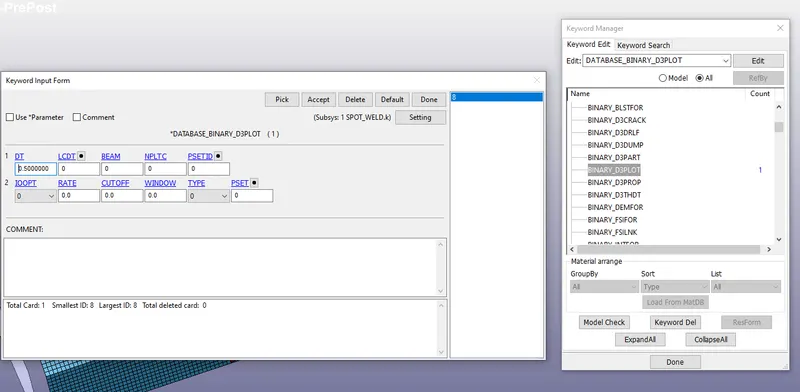
11. Create a database output as shown below.
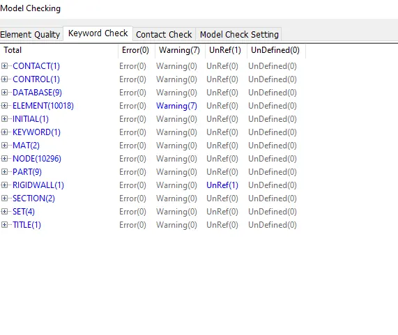
12. Next go to the model checker to check the errors and warnings as shown below.
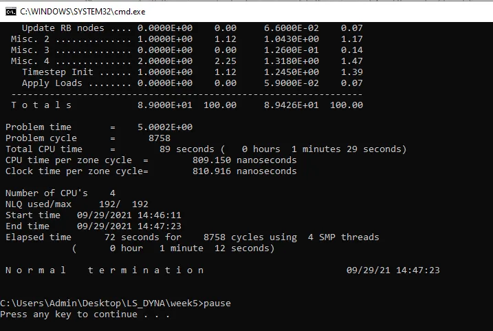
13. Next run the simulation on LS-Run as shown below.
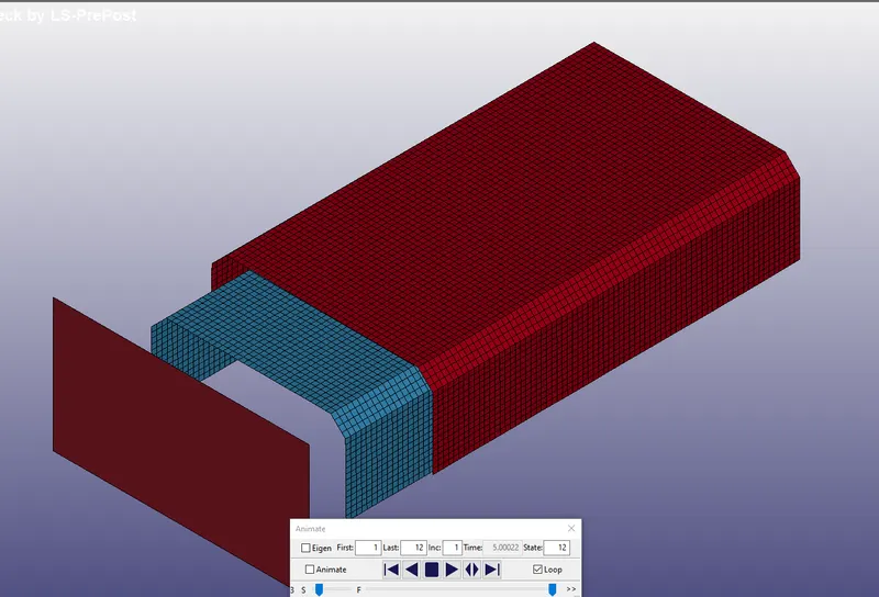
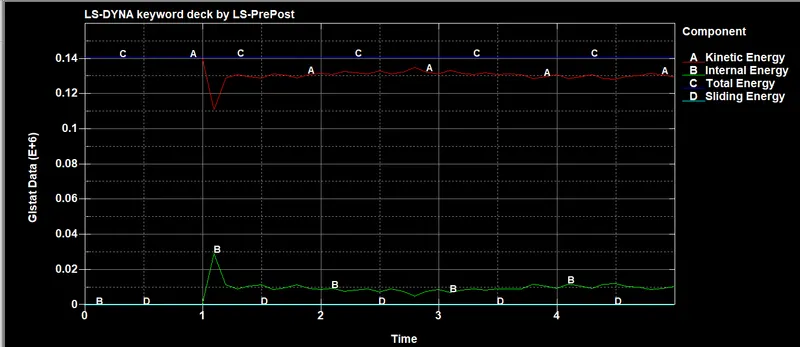
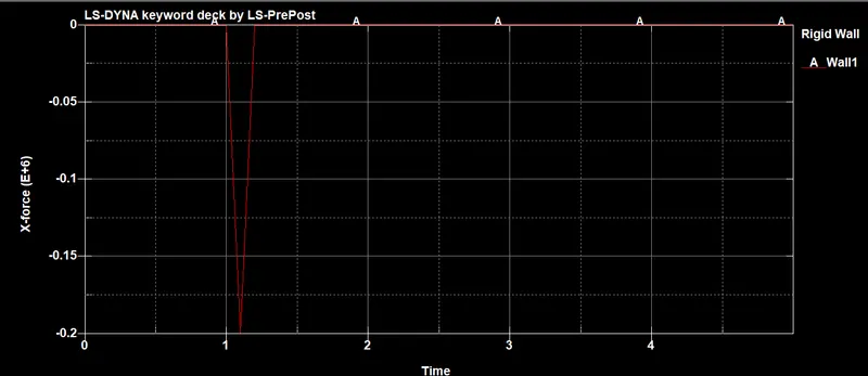
14. Next Open the D3plot in Ls-Pre post see the animation and plot the Stress, Strain and Energies as shown below.
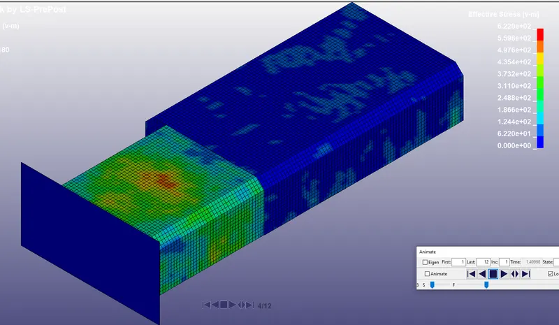
STRESS :
ENERGIES :
Rigid wall force :
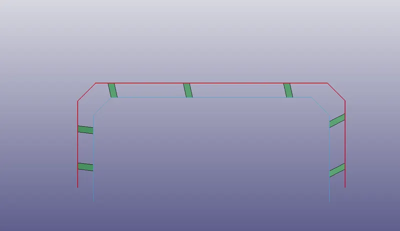
15. Next create the solid spot-weld as shown below.
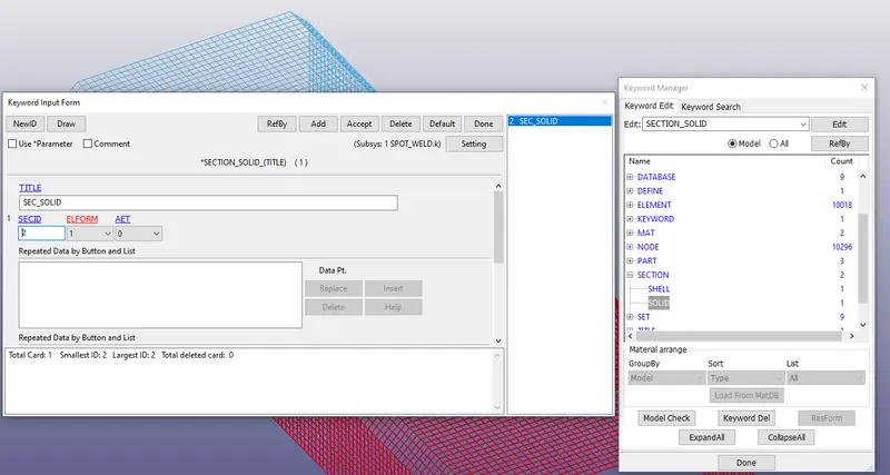
16 Create section solid and for Hexa elements as shown below.
17. Run the simulation on LS-Run as shown below.
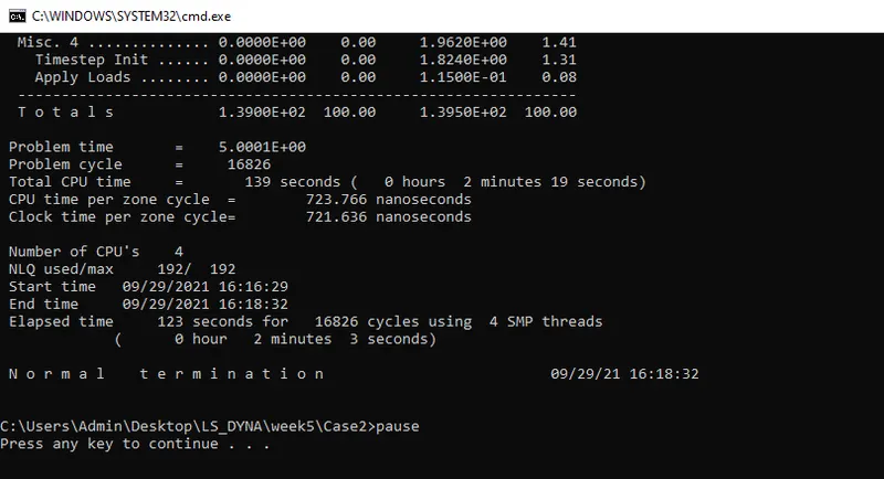
see the animations below.
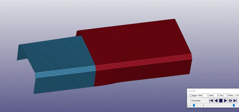
STRESS :
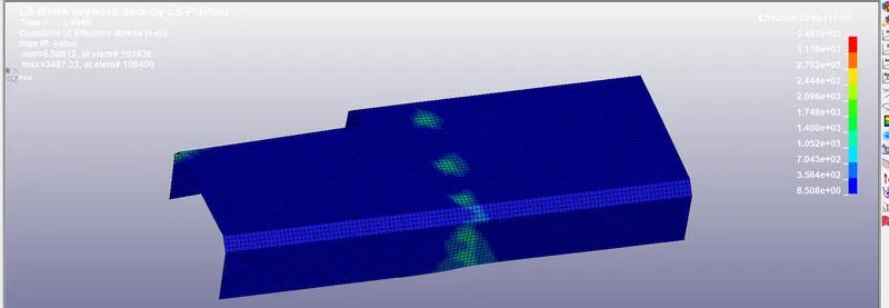
Shear stress :
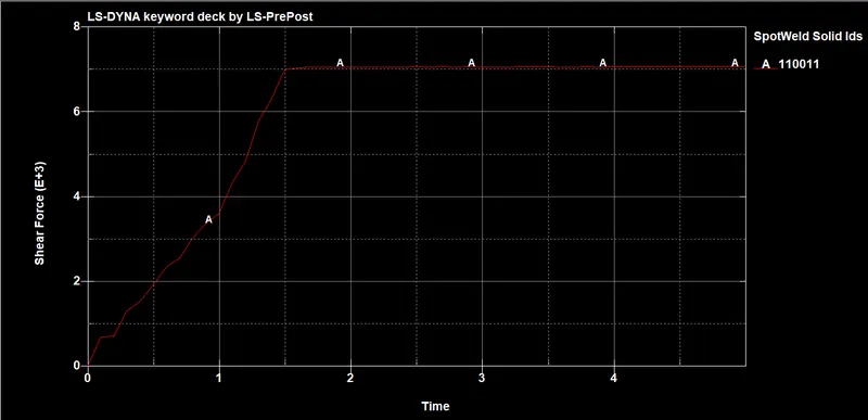
ENERGIES :
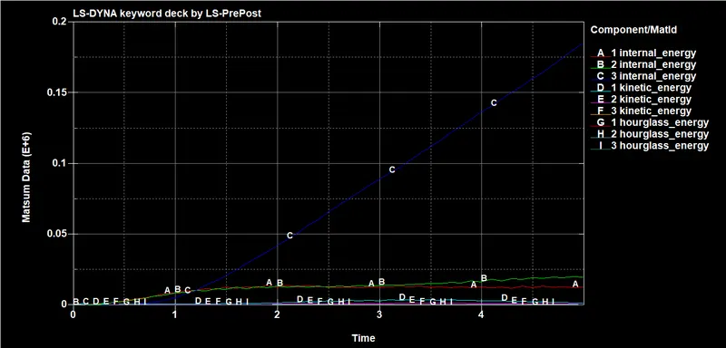
COMPARISON Of BOTH CASES :
| Spot weld | Stress |
| Beam Element | 6.220e+02 |
| Solid Element | 3.437e+03 |
CONCLUSION :
- In case 1 the beam elements of spot weld has been deformed because the component strikes the rigid wall with high velocity the beam elements can not withstand the given high velocity. so the upper component moves along with the lower component.
- In case 2 Solid elements of spot weld will not collapse and shear stress is increased.