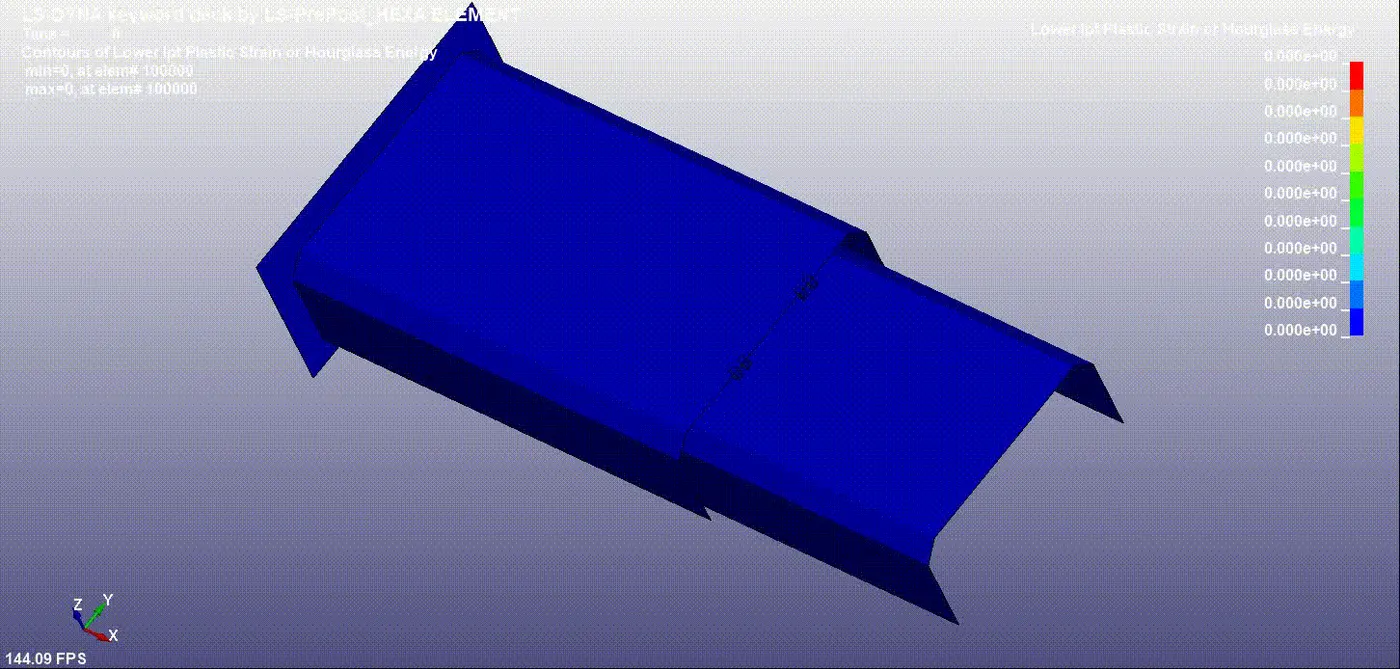
Week - 5 - Modelling Spotwelds
Objective:
To model spot weld for the given assembly of parts and perform crash test using LS DYNA software.
Introduction:
Weight reduction is one of the main parameters to be considered in Automobile industries for better fuel efficiency and performance. To replace the heavy structures in automobiles, high strength steel sheets are most commonly used as a structural members during recent years. Concerning the behaviour of such structures during a car crash the joints between high-strength materials are seen as critical points. Therefore the properties of welded joints, especially the failure behaviour at high velocities have to be taken into consideration
during the development phase.A simple model that is able to represent the failure
behaviour of spot welds in sheet metals has been developed and performed Crash analysis for various elements(beam & Solid elements) using LS-DYNA software.
Weld Creation:
Beam Element
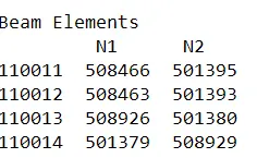
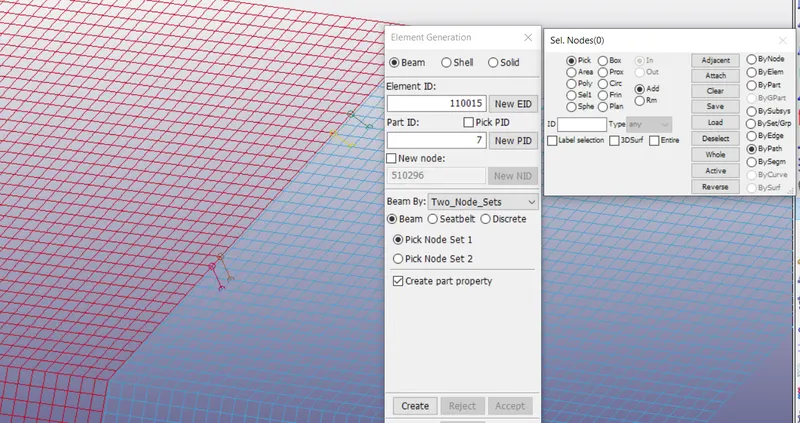
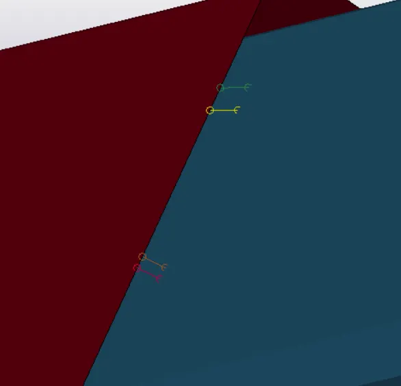
In the imported sheet metals the welds are created using Elements and Mesh - Element generation command in Ls Dyna prepost software. Two node sets is used to generate Beam element.N1 and N2 represents two nodal points.
Solid ELements:
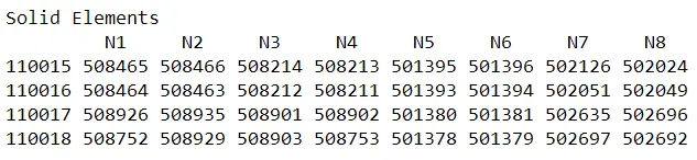
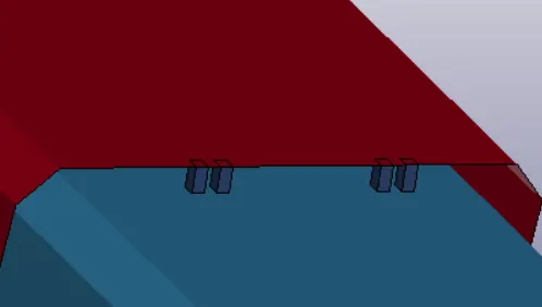
Solid elements are created using Elements and Mesh - Element editing- Hexa type command. Nodes should be selected in clockwise manner to generate hexa mesh.
Material Selection:
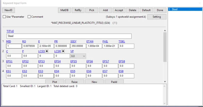
For sheets the materials is selected to be Steel. Keyword-Mat-PieceWise Linear Plasticity command is selected to define materials.
For Weld Mat_SPOTWELD in keyword option is selected
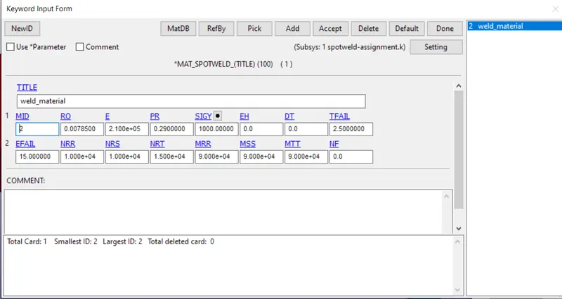
Failure time is choosen to be 2.5
Section
Section of the weld is selected by using Section-Beam in keyword command
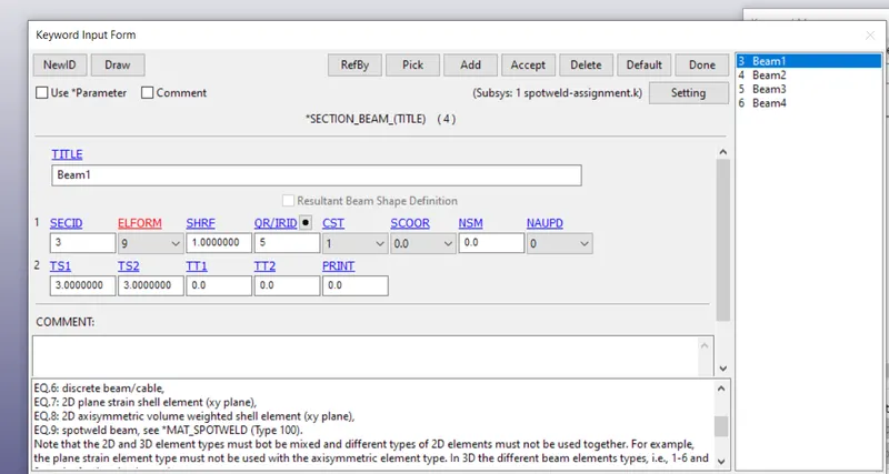
Element formulation 9 is used for spot weld.Since Mat_spotweld is valid for that type.The thickness of the weld is 3mm
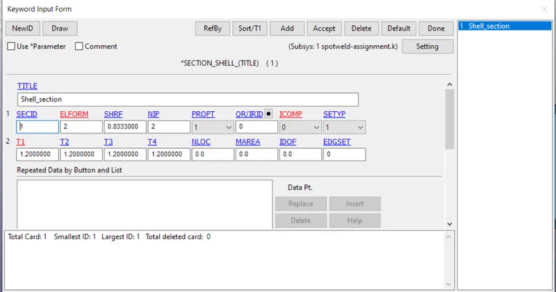
For sheet metal shell element is used
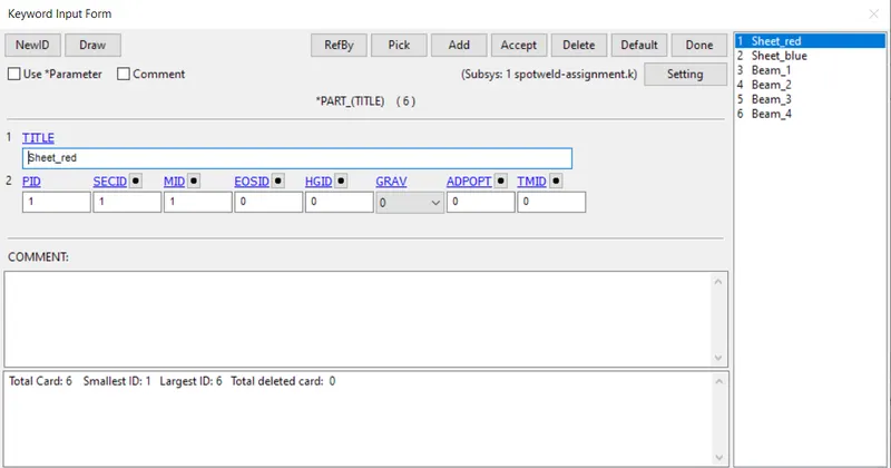
The materials and sections are linked by using part option in keyword.
Rigid Wall:
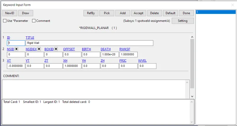
Rigid wall is created by using Keyword- Rigidwall planar command.
Velocity Generation:
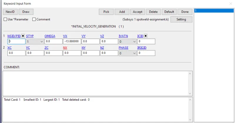
The sheet part travels at high velocity. To define the velocity keyword- Initial- Velocity generation is used. The model along with weld travels at 13.88mm/sec.Negative sign repersents opposite direction.
Contact:
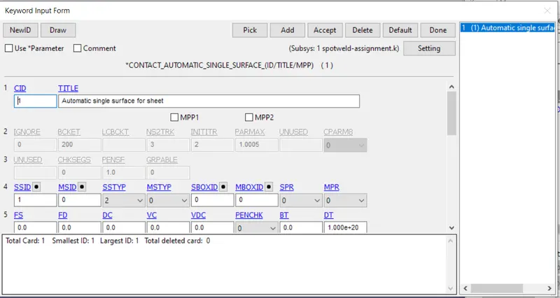
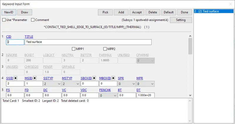
For contact automatic single surface and Tied shell edge to surface command is used.
In Contact automatic single surface,contact that happens within the sheet metals can be specified and in Tied shell edge to surface contact between slave (weld) and Master(sheets) are specified.Slave is one which has lower rigidity and Master is the one having higher rigidity.
Control:
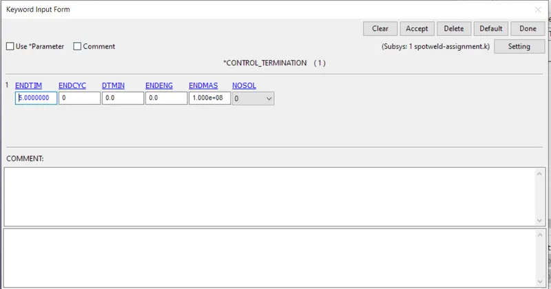
To determine the total simulation time control termination is used for the anlysis the time is chosen to be 5ms
Binary D3 Plot
After running the simulation it is necessary to write output data for simulation purpose and it can be done using d3plot.The output data is written at a time interval of 0.5ms.
ASCII
GLSTAT- Interanl Energy, Hour glass energy, Kinetic energy plot
SLEOUT- sliding interface energy
SECFORCE- Cross sectional force
NODOUT-Nodal properties like displacement, acceleration etc
SWFORCE- spot weld nodal reaction force.
Results and discussion:
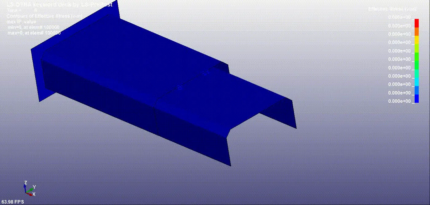
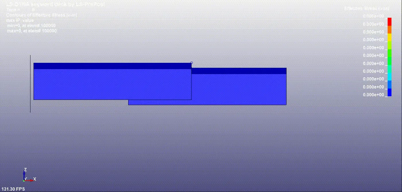
Spot weld beam
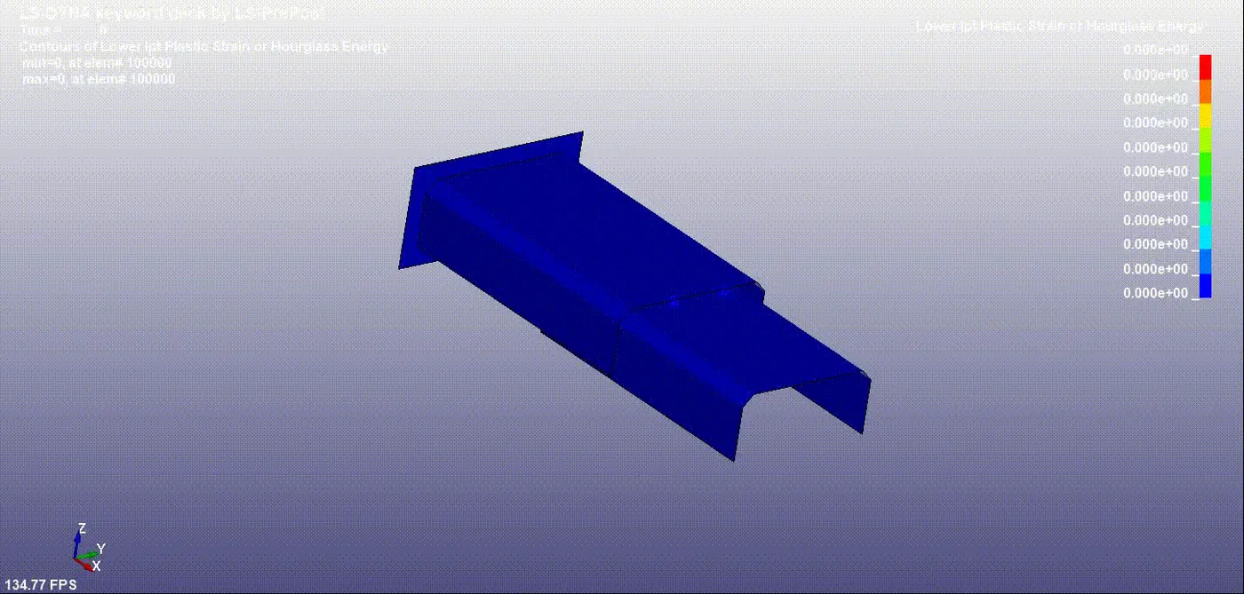
HOUR GLASS ENERGY
Axial Force
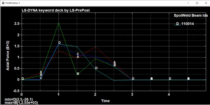
Maximum axial force for beam elements is 2.5e+03 and it occurs at 1 sec
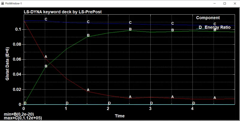
From the graph it can be inferred that internal energy increases gradually with time and attains a constant value whereas kinetic energy decreases from maximum to minimum.
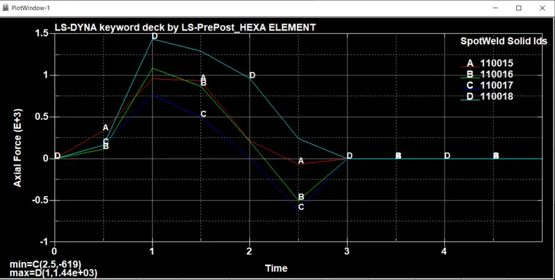
For solid elements