Week - 5 - Modelling Spotwelds
Week - 5 - Modelling Spotwelds
Aim: Simulate the given model with beam and solid spotweld by assigning the appropriate key cards.
Explanation:
The given model has only the nodes and element data and this spotweld.k file is imported into LS Dyna prepost from file -> open
For this simulation to run we need a certain keycards to be present which are mandatory and other keycards for getting ouput requests.
After importing the file into prepost,
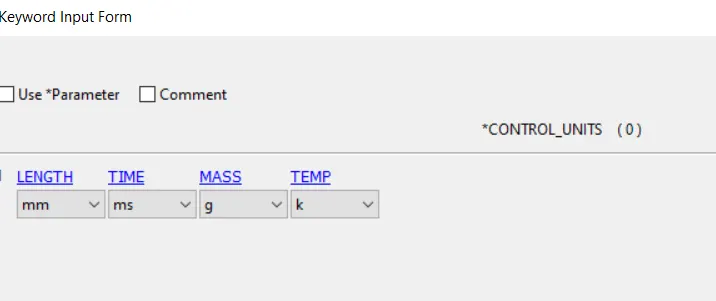
1) The units are given so that the parameter values are given with repect to the unit system. This is done from keyword manager -> control -> units
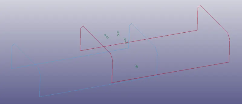
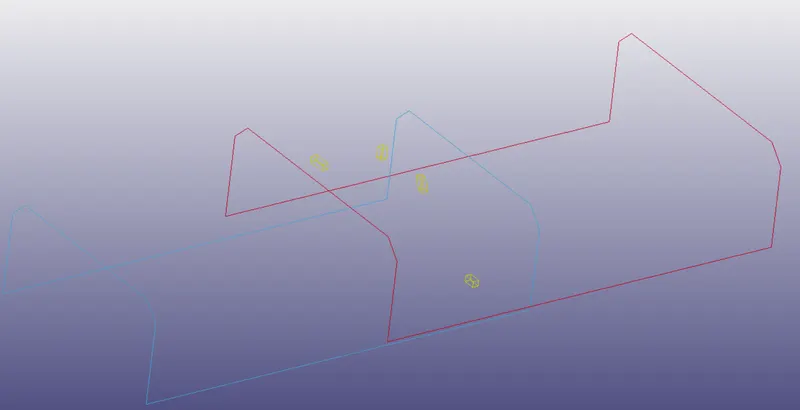
2) Connecting the two parts using 4 beam elements symmetric about central axis.
This is done by forming elements from element generation
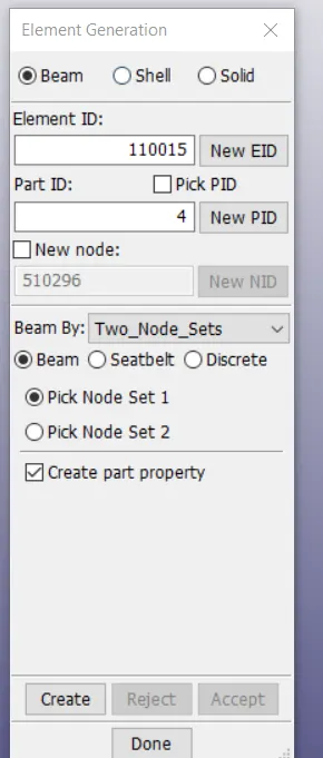
By picking two sets of nodes one set on each part so that the nodes are connected by beam element
Similarly we can make connections between the nodes of the parts with solid elements from element generation
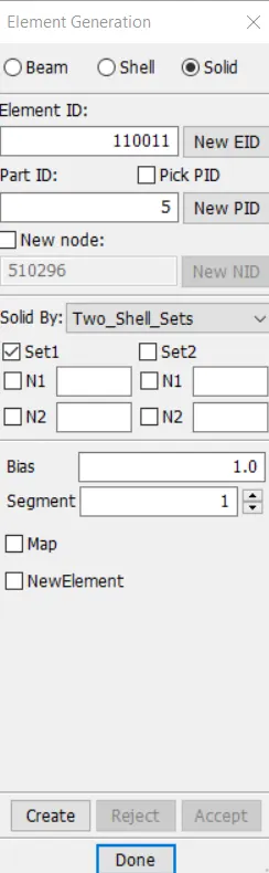
Here selection of sets are done for element by element, where N1,N2 are selected in direction same as set2 on part 2
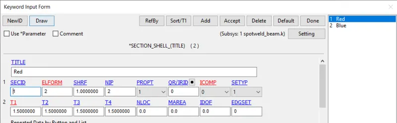
3) Defining Section card for shell for the model from key word manager -> all -> section -> shell for parts
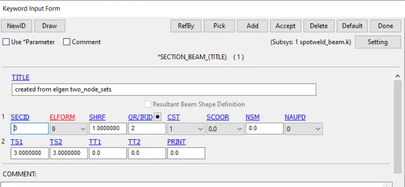
Defining Section card for beam elemets from key word manager -> all -> section -> beam
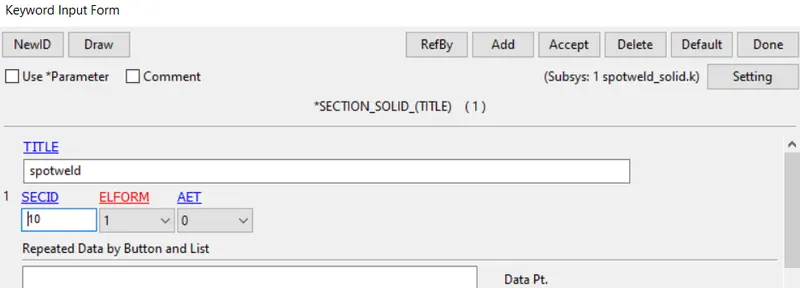
Similarly for solid element
4) Material card generation from key word manager -> all -> MAT -> Type 1 for elastic material.
The values are with repect to the given unit system.
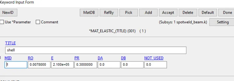
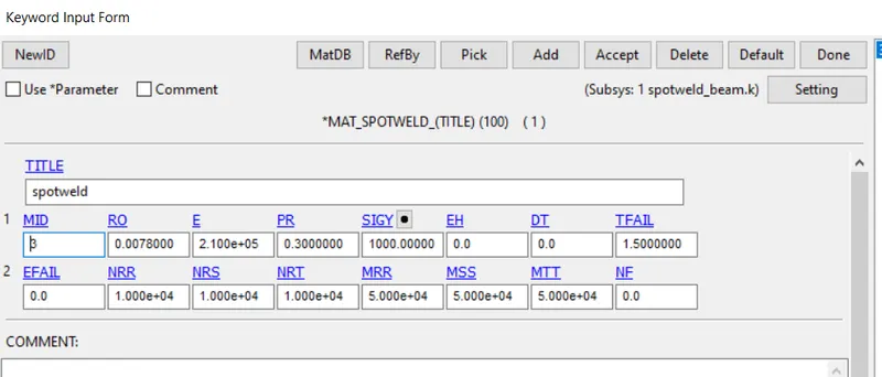
Similarly for beam material with recommended material and TFAIL is given for half time failure and NRR, NRS, NRT are takien high so that it fails at specified time.
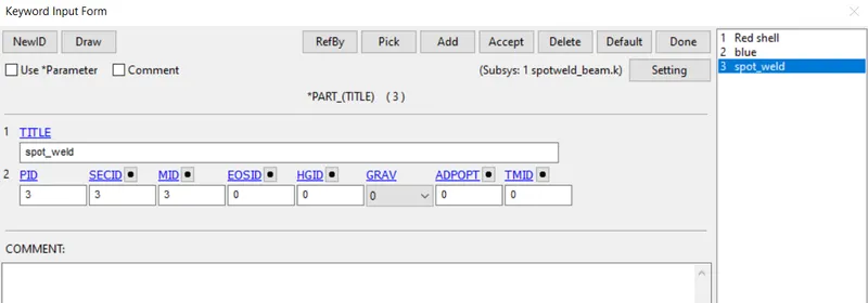
After the section id and materail id are created, they are then assigned to the parts in the model.
From key word manager -> model -> PART in SECID and MID for Box
4) Rigidwall
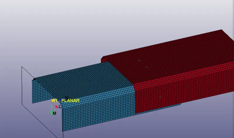
This crash is to happen with the rigidwall and this is formed
From Model and Part -> Entity Creation -> Rigidwall
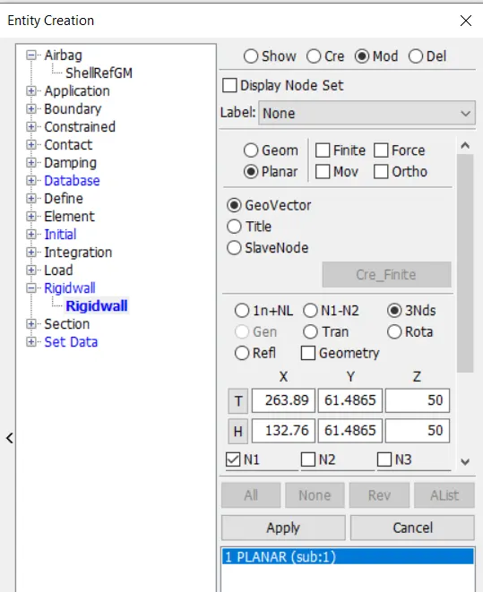
Here the N1, N2 and N3 are taken at extreme end of the crash box in a way such that the normal is towards the box and this rigidwall is translated so that crash can happen after specific time.
5) Intial Velocity
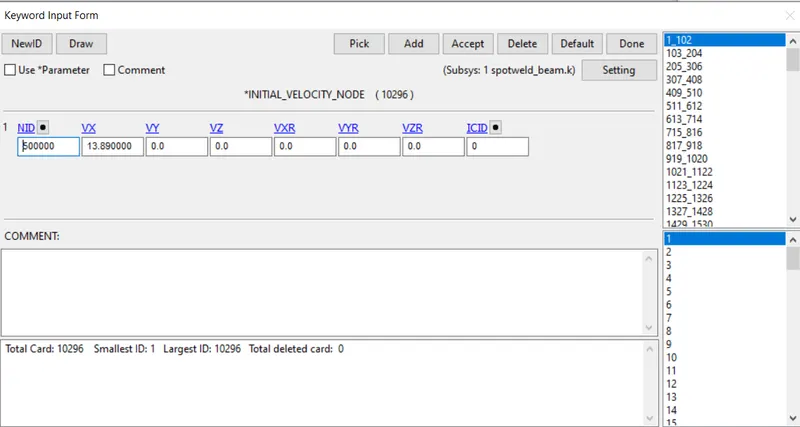
This velocity for the box is taken to be in +ve x axis direction and all the nodes of the part are picked
From Model and Part -> Entity Creation -> Intial -> Velocity
This can be seen from keyword manager.
6) Contact card
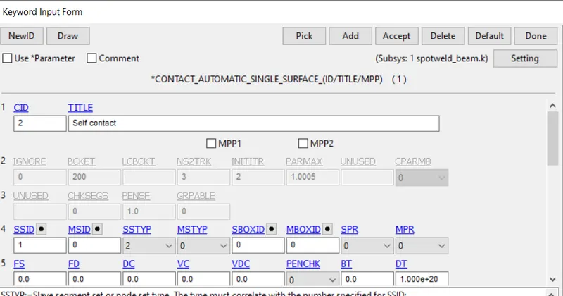
Since it is collision with rigid wall, we use AUTOMATIC_SINGLE _SURFACE, we can just define slave nodes
Here we have two different parts, so to define them as single set form create Entity -> Set data -> Part
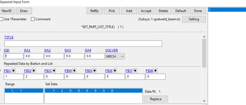
Using this part id the contact is defined.
SInce the beam are present the contact definition for these beams are defined from keyword manager -> Contact -> tied contact egde to surface
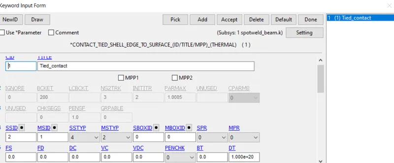
Here slave node set is created with nodes of only beams.
Similarly when solid connections are used Spotweld contact card is used
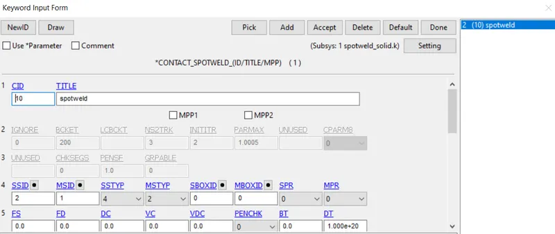
7) Control cards
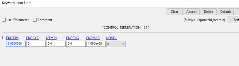
After the contact, control cards are chosen fron keyword manager -> all -> control -> Termination
The end time is chosen to be 3 ms to check before and after collision
Energy
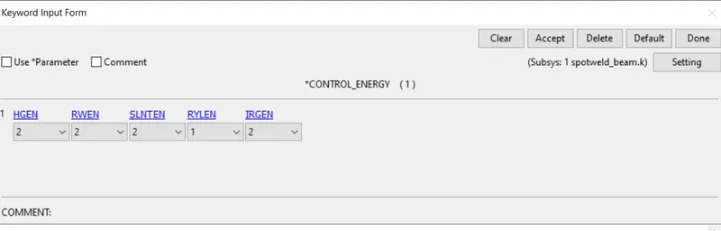
The rest options are kept default.
7) Database card
After the control cards, the output requests are updated from Keyword manager -> all -> Database ->
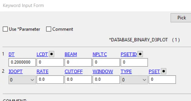
Binary_d3plot for contours and animations
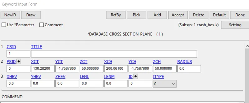
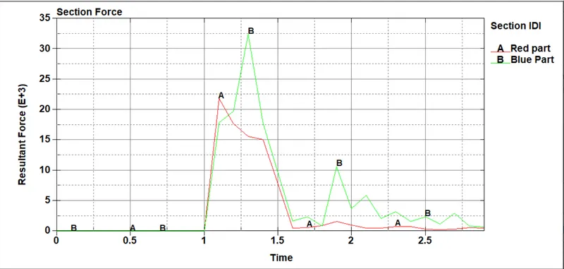
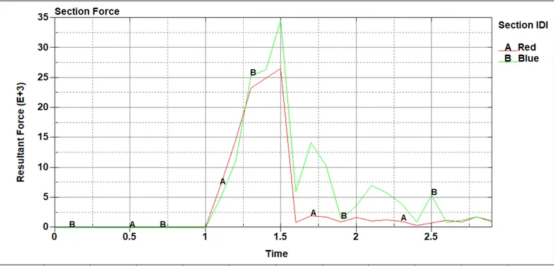
Cross section plane for force at cross section
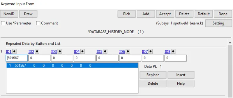
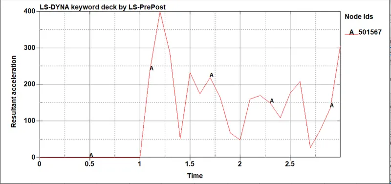
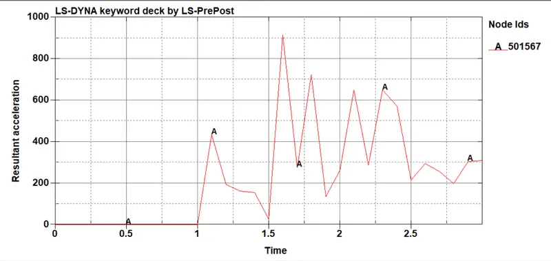
History node for getting acceleration at specified node
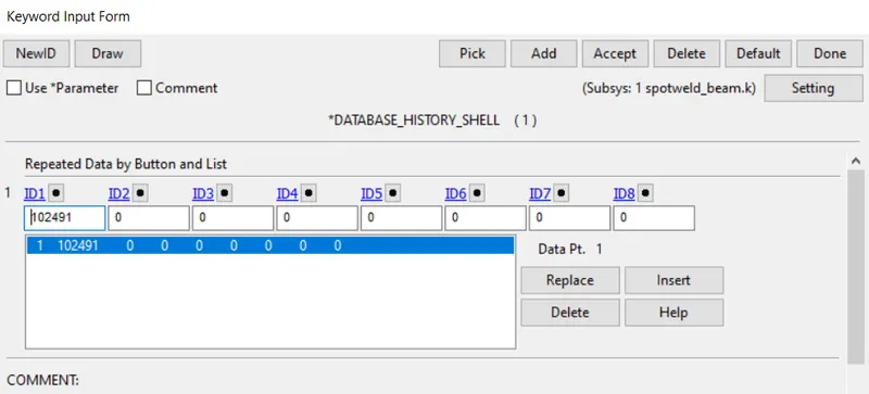
History shell for getting directional stress at specified shell
The energy values, forces on parts, nodes are updated in ASCII
ELOUT for elemental output
GLSTAT for energy values
NCFRC are nodal Interface forces
SLEOUT for sliding energy
NODOUT for values at specified node
SECFORC for section forces
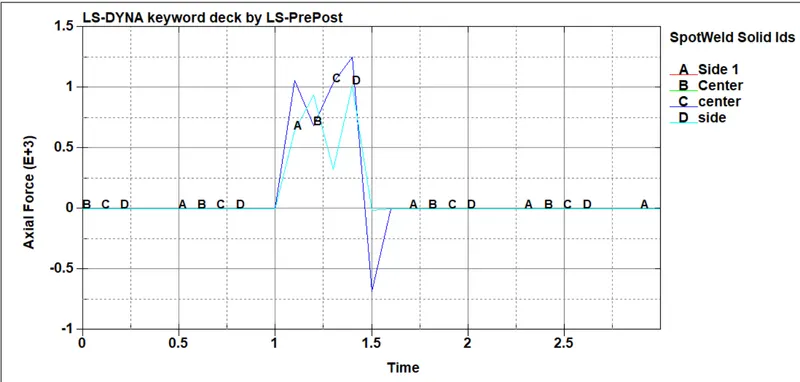
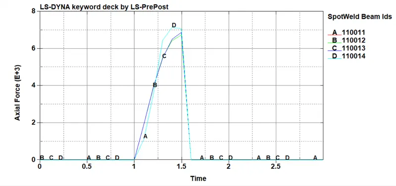
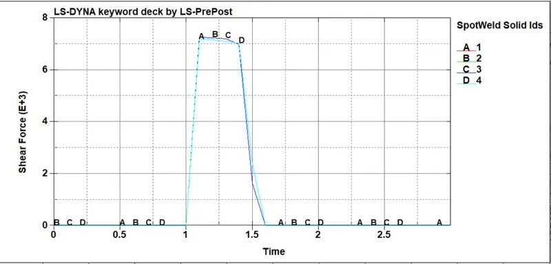
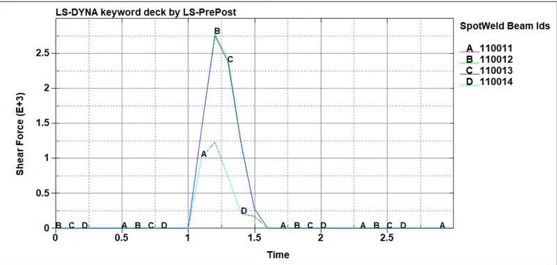
SWFORC for spotweld forces
with DT as 0.1 ms
8) After this keyword cards are created and updated, then this keyword file is saved.
Then opening LS RUN and run for both the models for beam and solid elements.
Results:
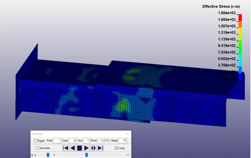
The d3plot is opened as binary file in LS prepost and following max stress contour is obtained around time of impact for solid spotweld before failure.
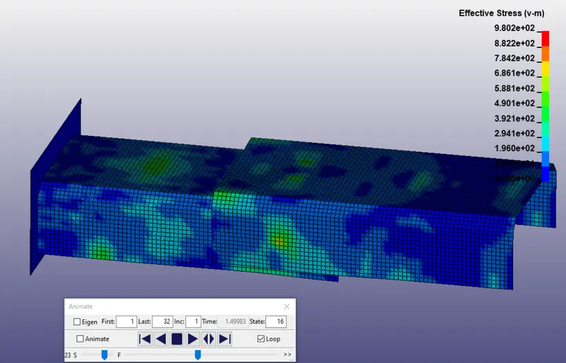
The d3plot is opened as binary file in LS prepost and following max stress contour is obtained around time of impact for solid spotweld after failure.
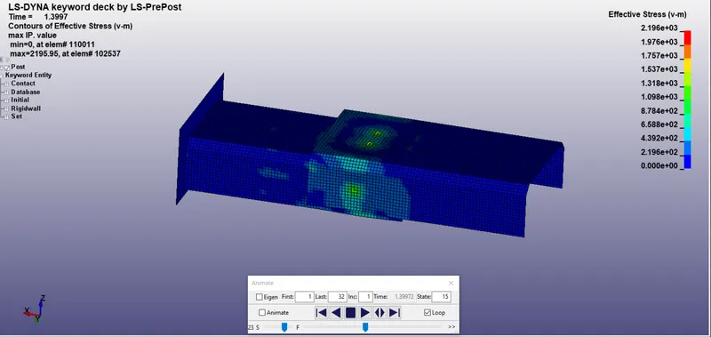
The d3plot is opened as binary file in LS prepost and following max stress contour is obtained around time of impact for beam spotweld before failure.
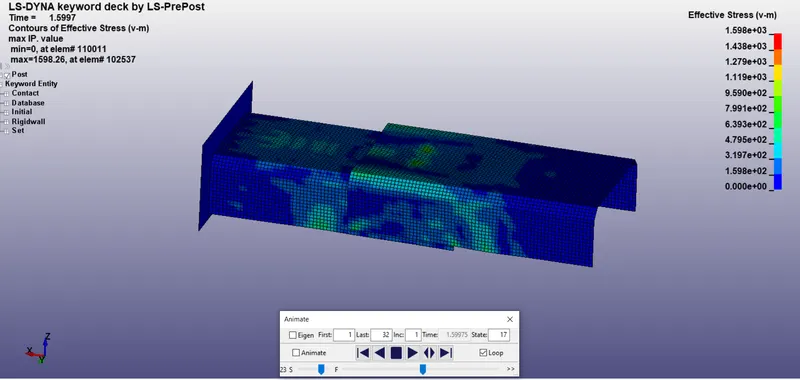
The d3plot is opened as binary file in LS prepost and following max stress contour is obtained around time of impact for beam spotweld after failure.
Cross sectional forces on the taken cross section for solid spotweld from secforc on Ascii
Cross sectional forces on the taken cross section for beam spotweld from secforc on Ascii
Acceleration plot at specified node for solid spotweld from nodout on Ascii
Acceleration plot at specified node for beam spotweld from nodout on Ascii
X Stress plot along X direction on specified element from elout on Asci for solid spot weld
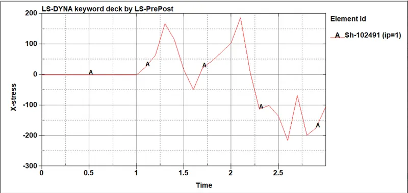
Y Stress plot along X direction on specified elemet from elout on Asci for solid spotweld
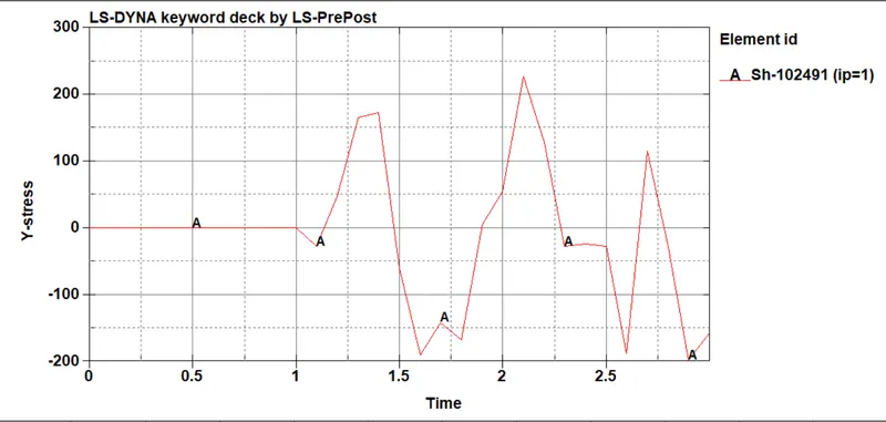
Z Stress plot along X direction on specified elemet from elout on Asci for solid spotweld
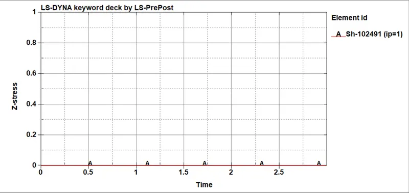
X Stress plot along X direction on specified elemet from elout on Asci for beam spotweld
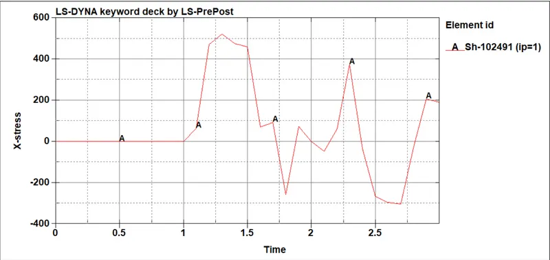
Y Stress plot along X direction on specified elemet from elout on Asci for beam spotweld
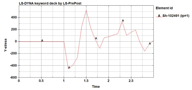
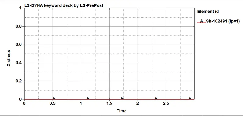
Z Stress plot along X direction on specified elemet from elout on Asci for beam spotweld
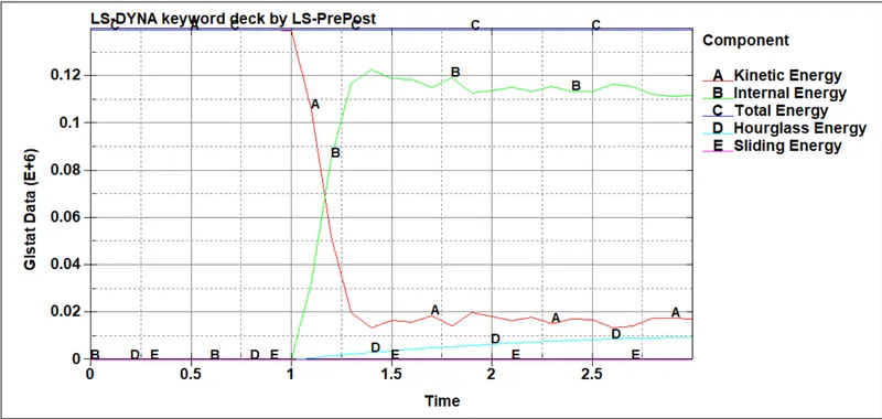
Energy plot for solid spotweld from glstat on ASCII
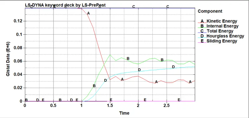
Energy plot for beam spotweld from glstat on ASCII
Axial force on solid spotweld
Axial forces on beam spotweld
Shear force on solid spotweld
Shear forces on beam spotwelds
Conclusion:
The axial forces and shear forces are less than the given NRR, NRS, NRT.
The given spotweld models are successfully simulated in LS Dyna.