Week - 5 - Modelling Spotwelds
Objective:
In this assignment, you will model spot welds for the given assembly of parts and run a crash test similar to the one in assignment 4. Details about the spotweld location are in the image below. The yellow line signifies the spotweld directions. You need to use 3-7 spot welds along this line, in a symmetric manner, before running the simulation
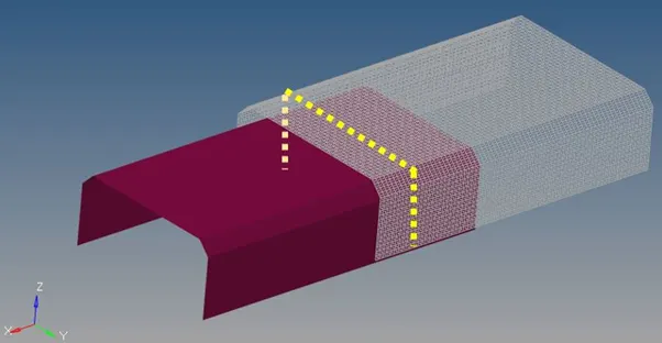
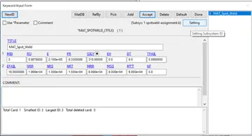
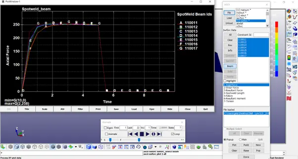
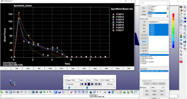
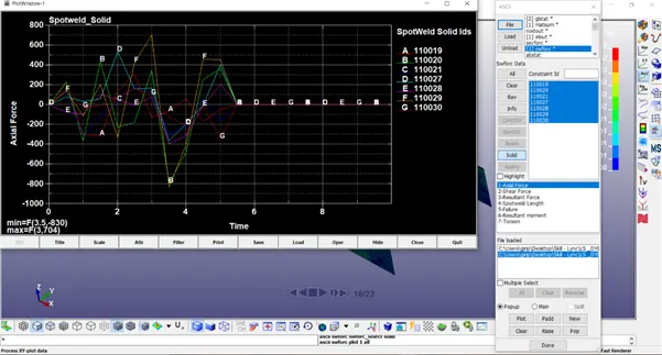
The spot welds should be modelled using beam elements and solid elements separately. While using solid elements, one spotweld should have one solid element. The axial and shear force should be compared among beam and solid elements. The same material card using *MAT_SPOTWELD should be used for both beam and solid elements. You can use steel material data for *MAT_SPOTWELD cards and calibrate the failure data according to your results. The best simulation should have a failure at half of the termination time.
Procedure:
- Open the given (spotweld-assignment.k) input keyword file in Pre Post of LS-DYNA.
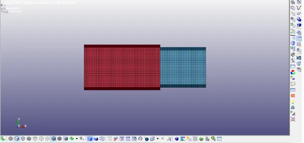
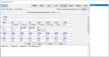
- Create the material card (Keyword-MAT- 024 PIECEWISE LINEAR PLASTICITY) for steel with values in gm – mm – ms.
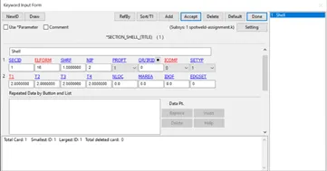
- Create a Section for the shell elements in the crash box (SECTION - SHELL) with a thickness of 2
- Edit Part keyword – with Material Id, Section Id created for both top and bottom part
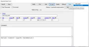
- The outer end of the top part is constrained in all directions by creating a node-set.
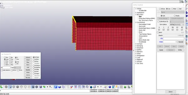
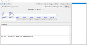
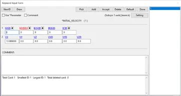
- Create Node set for Velocity (all the nodes) of the bottom part
- Create Spot welds along the line as shown in the figure.
Beam Elements:
Mesh – Element Generation – Beam – Give Part ID – Select beam by two nodes – Pick node-set from top and bottom part – Create.
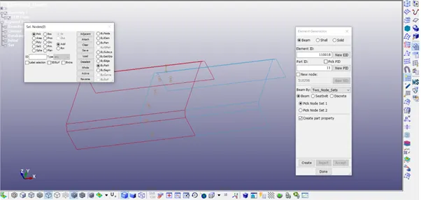
Solid Elements:
Mesh – Element Tools – Element Editing – Create Type – Hexa – Select 8 nodes to create the Solid element
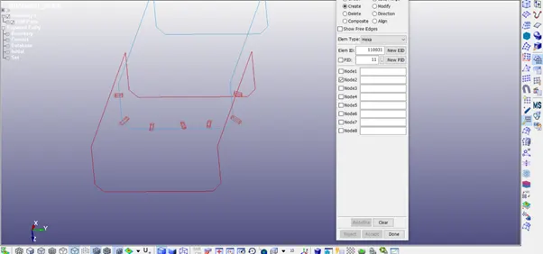
- Material Card for Weld Element (both Beam & Solid)
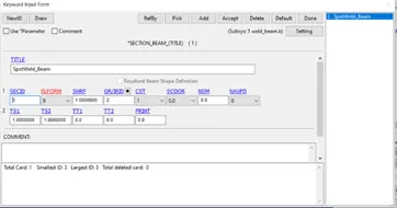
- Create Section Card for Beam & Solid Element accordingly.
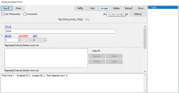
- Assign the mat & sect cards to the respective weld parts
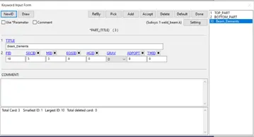
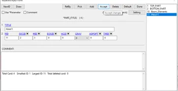
- Create contact cards for the weld elements
Beam –
Create Node Set ID by selecting the nodes of the beam elements - Slave
Create Part Set ID by selecting both parts – Master
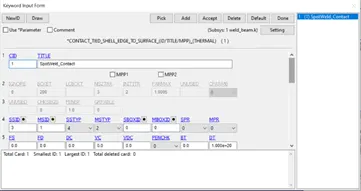
Solid –
Create Node Set ID by selecting the nodes of the solid elements (8 nodes each) - Slave
Create Part Set ID by selecting both parts – Master
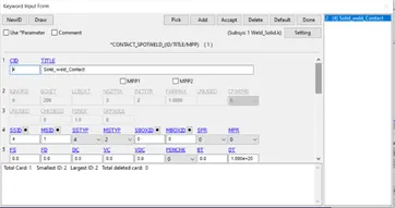
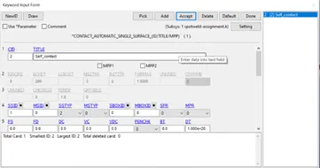
Create Self contact card (both Solid & beam) by selecting part set Id as slaves
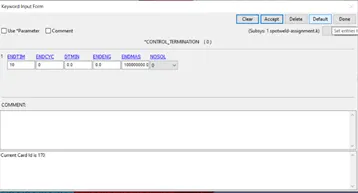
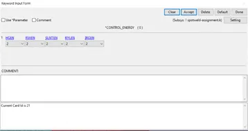
- Set the ENDTIM in control termination, DT in DATABASE_BINARY_D3PLOT, and also create the Control Energy card as follows
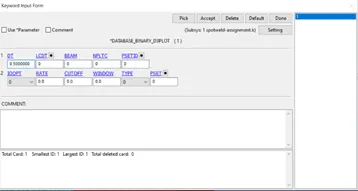
- Add the required ASCII files in the Database Keyword. - ELOUT, GLSTAT, MATSUM, SWFORC, NODOUT, SECFORC
- Add Time History Card as follows:
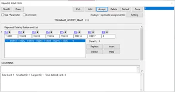
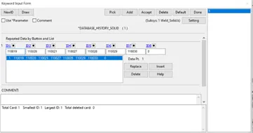
- Save the Keyword file as (Weld_Solid.k, Weld_Beam.k) in a new folder and run the keyword files in LS – Run.
- Open LS – PrePost, Import the D3 plot file created during the simulation.
- In the Fringe Component option, Select Von-mises stress for the contour plot and save the von mises animation videos.
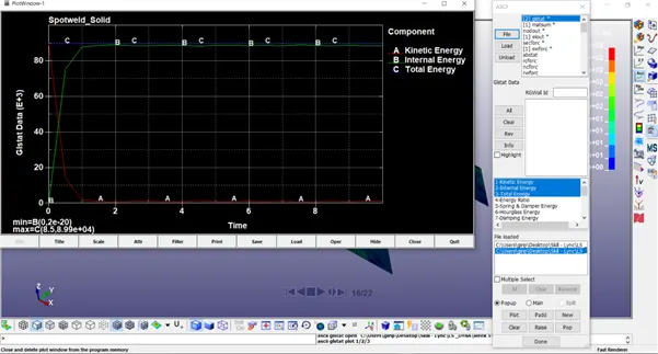
- Energy Curves – Plot Energy Curves using GLSTAT file
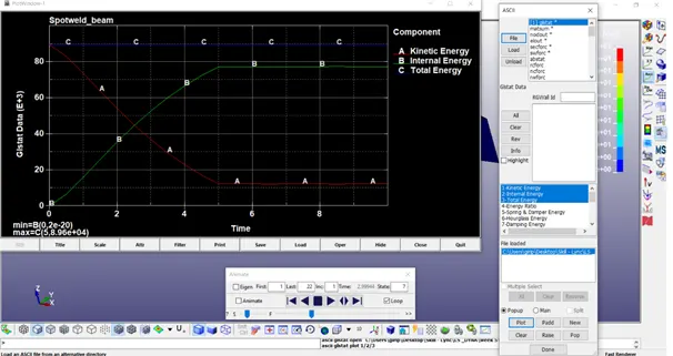
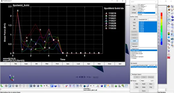
- Axial Force & Shear Force using the SWFORC file
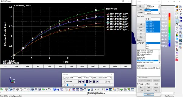
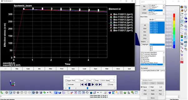
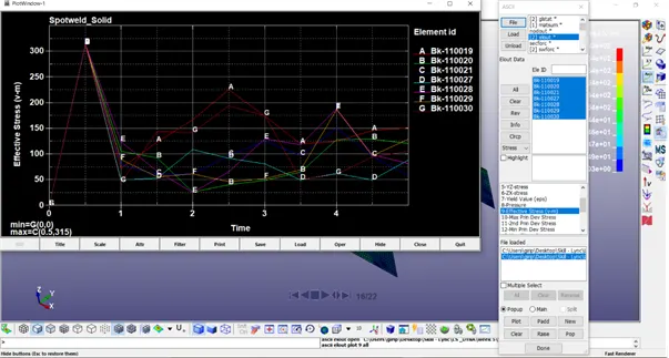
- Effective Plastic Strain & Stress curves
Conclusion:
Thus, we learnt about how to connect the two surfaces using beam & Solid welds assigning material and other corresponding keywords for them, simulating the model, and analyse the solution.