Week - 5 - Modelling Spotwelds
Objective : Model spotwelds for the given assembly of parts and run a crash test
Procedure:
1. The Model was having 2 Plates one at the bottom and and another at the top, first this were renamed to Top and bottom by parts tab
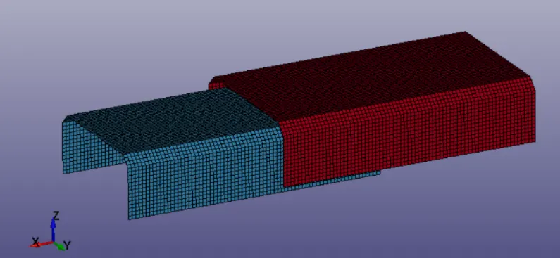
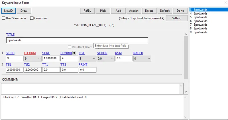
2.After this spot welds were created using the Mesh tab and ELFORM was selected as 9 because MAT Spotweld only applies 9 and thickness was given as 2 mm
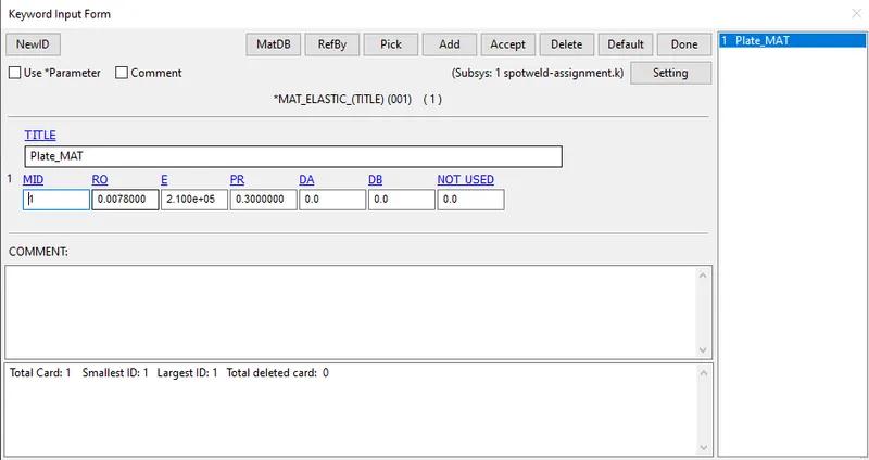
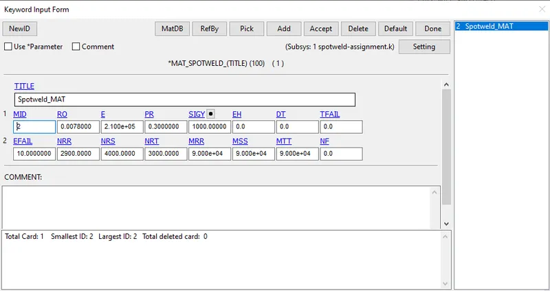
3.Then after this material property was defined for the Parts and spotweld, for spotweld MAT 100 was defined and For plates the MAT 24 was defined.
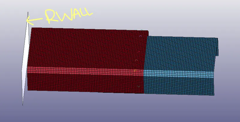
3.After this rigid wall was created opposite to the model,in such way that it helps in occurance of crash
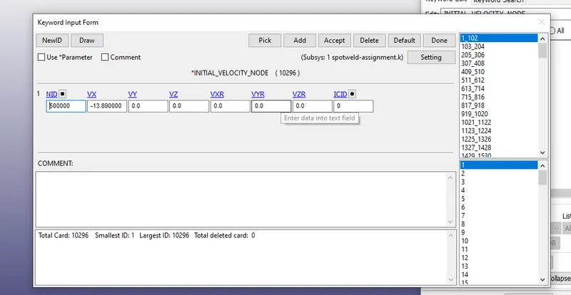
4.After this initial velcoity was assigned to parts in the Direction X-Axis it was assigned in the negative X such that it crashes the RWALL
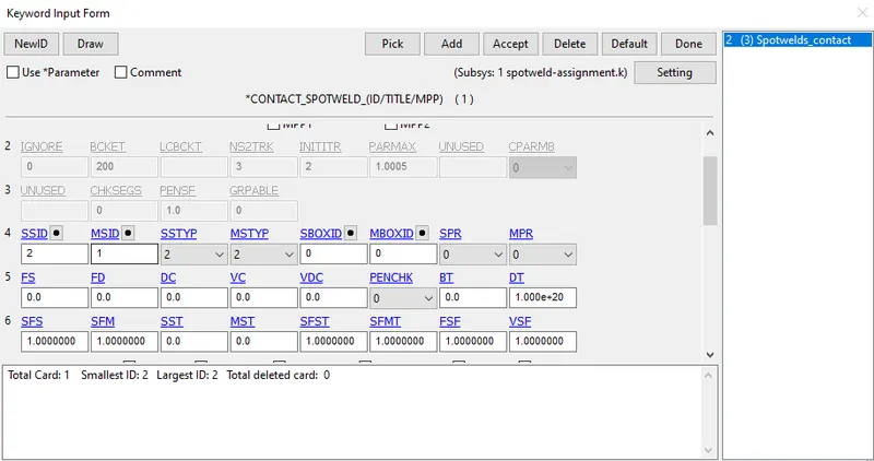
5. After this contact was defined for the Plates and spotwelds in this Spotwelds were considered as Slave and Parts as Masters
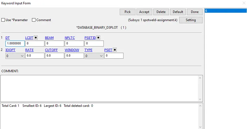
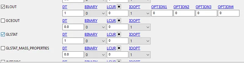
6.After this the Ouput request were created for the simulation and Temrination stop time was also asigned and dt was requested for every 1 ms
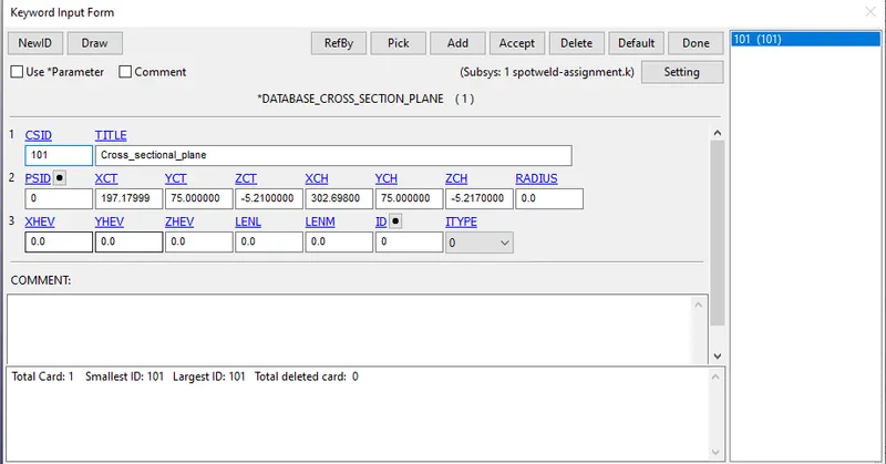
7.After creating outputs one more output was introduced which is the Cross sectional plane along the centre of the the plate
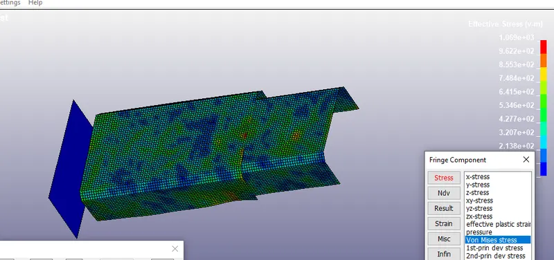
8.The below is von misses stress which helps in understanding the forces along the Model and also helps to understand the behaviour of spotwelds during the carsh
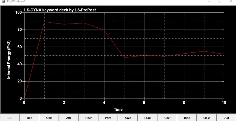
9.Below are the energy plots for the model
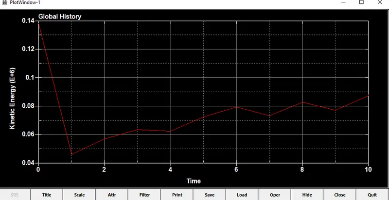
Kinetic energy is higher during the start and reduces gradually with respect to time and gets converted to internal energy
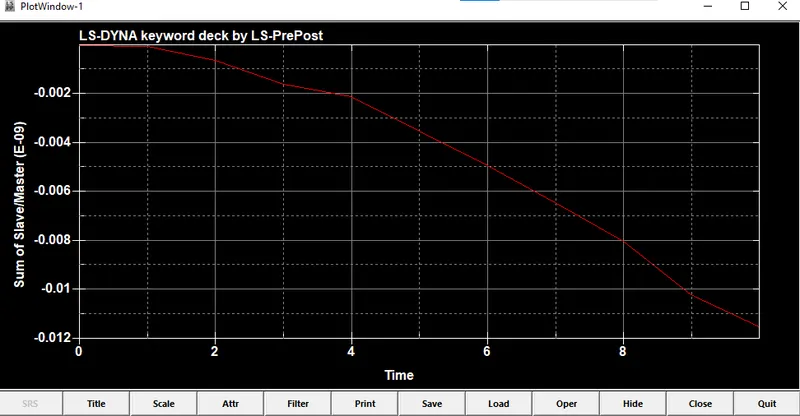
10. Below graph explains the behaviour of the spotwelds during the simulation , the force with stand by the spot wleds is higher during the simulation and at the end the welds starts getting deleted
3. sectional forces along the nodes at the middle
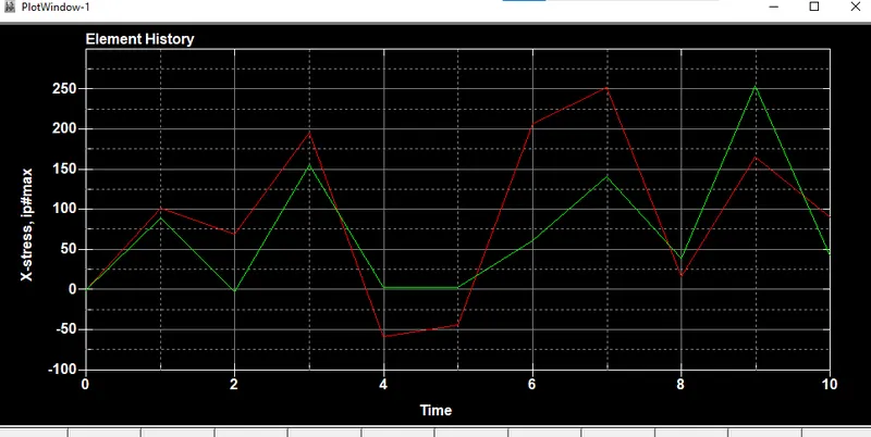
the displacment is goes on increasing with the time step as the internal energy increases on the nodes