Week 5 Challenge : Surface wrap on Automotive Assembly
Aim :- To make a surface wrap for automotive assembly.
Steps :-
i. Import the CAD file.
ii. Display setup.
iii. Geometry clean up/Repair.
iv. Assemble the geometries.
v. Generate surface wrap
Procedure :-
i. Importing CAD file - Engine
Go to file > Open > Browse the location of the model > Select it and click enter.
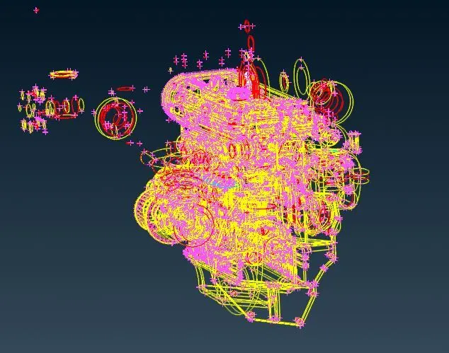
ii. Display setup -
As we can see the imported CAD file is in wire frame. We need to set it right for use.
Bottom tool bar > Shadow.
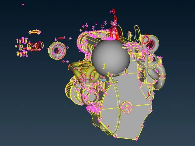
iii. Geometry clean up/Repair -
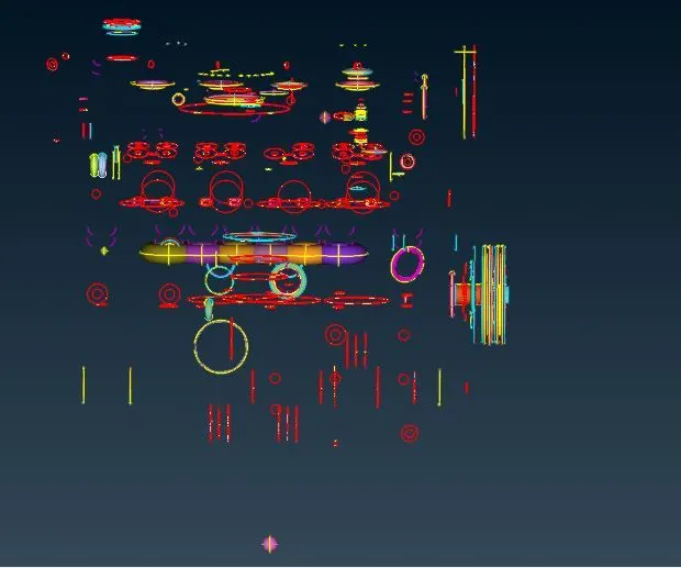
As we can see there are several single cons and triple cons present. Single cons means there is only one surface. So we can turn the single cons into double cons by adding new surfaces over there by doing some operations. And triple cons means there are more than two surfaces , so we need to delete the extra surfaces.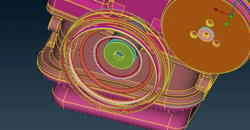
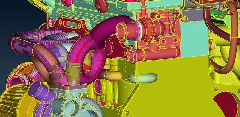
In the above image we can see that there are several extra surfaces (rings) present which is not needed so we can delete them too. There are also overlapped surfaces which need to remove. Pipes are needed in the surface wrap so we can delete them too.
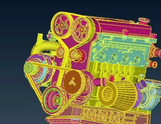
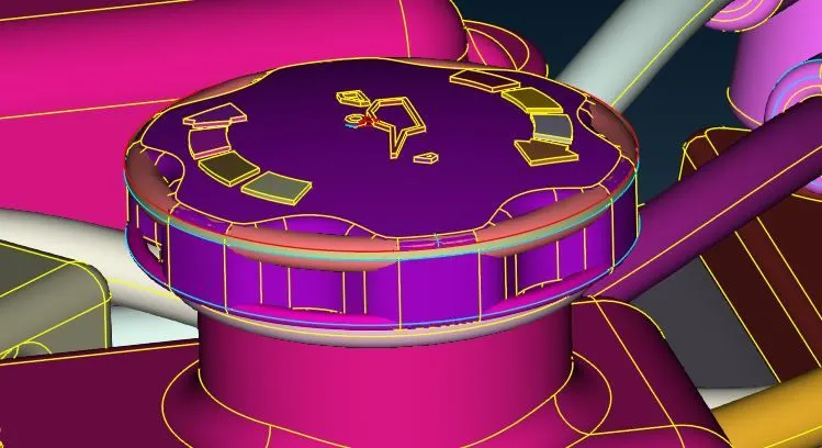
In the above images belt is not required so we can delete that part and in the second image overlapped surfaces are also getting deleted.
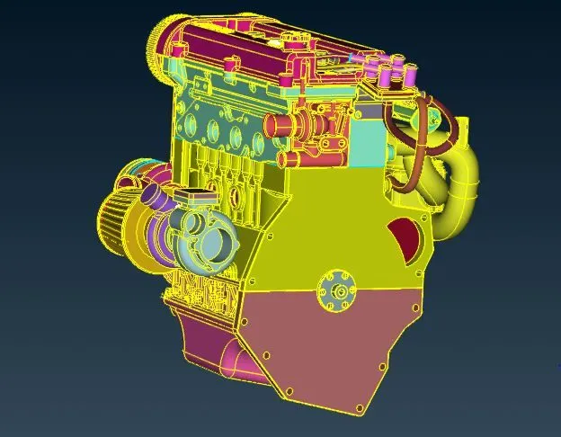
After removing all the unwanted surfaces and parts of the whole geometry , it does look like shown above.
ii. Importing CAD file - Gearbox
Go to file > Open > Browse the location of the model > Select it and click enter.
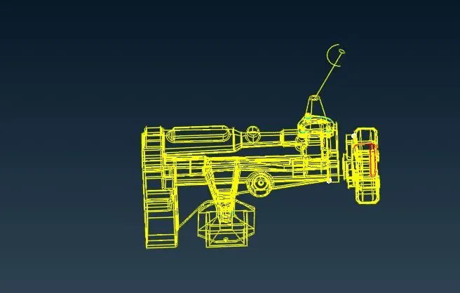
ii. Display setup -
As we can see the imported CAD file is in wire frame. We need to set it right for use.
Bottom tool bar > Shadow.
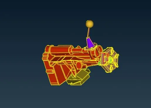
iii. Geometry clean up/Repair -
As we can see there are several single cons and triple cons present. Single cons means there is only one surface. So we can turn the single cons into double cons by adding new surfaces over there by doing some operations. And triple cons means there are more than two surfaces , so we need to delete the extra surfaces.
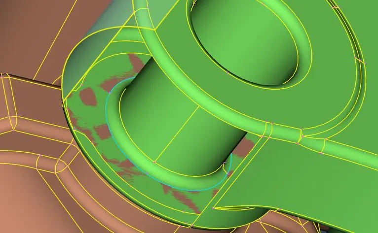
In the above image we can see that there is extra overlapped surface present which is not needed so we can delete them too.
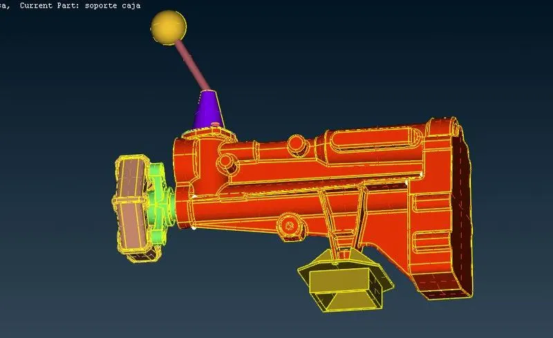
After removing all the unwanted surfaces and parts of the whole geometry , it does look like shown above.
iii. Importing CAD file - Transmission
Go to file > Open > Browse the location of the model > Select it and click enter.
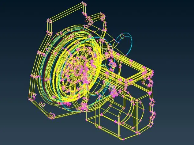
ii. Display setup -
As we can see the imported CAD file is in wire frame. We need to set it right for use.
Bottom tool bar > Shadow.
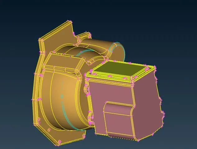
iii. Geometry clean up/Repair -
As we can see there are several triple cons present. triple cons means there are more than two surfaces , so we need to delete the extra surfaces.
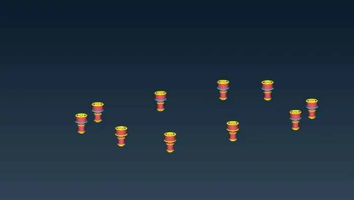
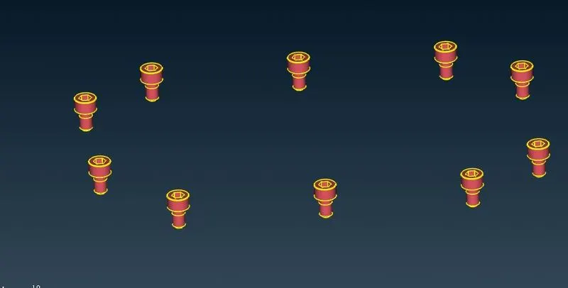
After deleting extra surfaces from the screws it does look like shown above.
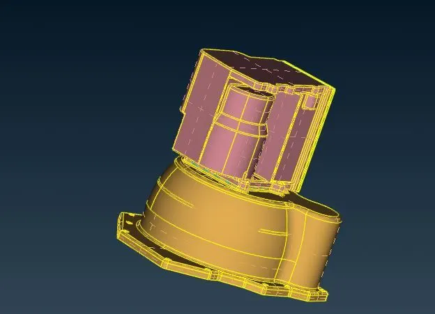
After removing all the unwanted surfaces and parts of the whole geometry , it does look like shown above.
iv. Assemble the geometries :-
Now we are going to assemble these three geometries. File > Merge and select the geometries.
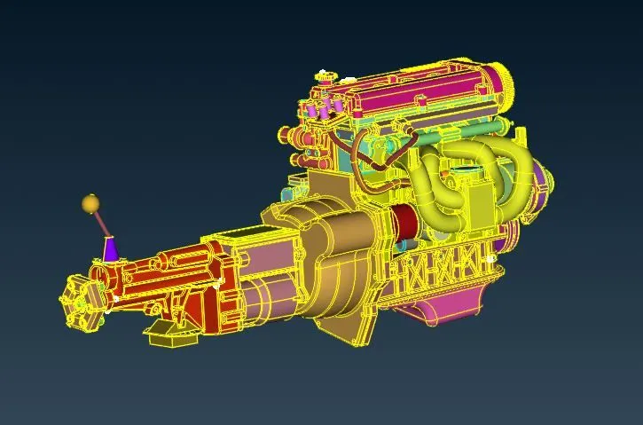
Now for surface wrap we need to fill all the holes presents in the assembled geometry.
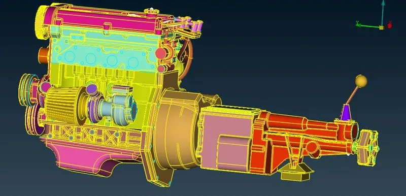
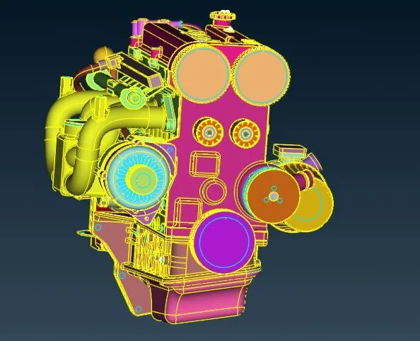
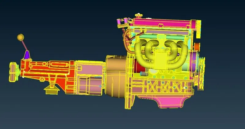
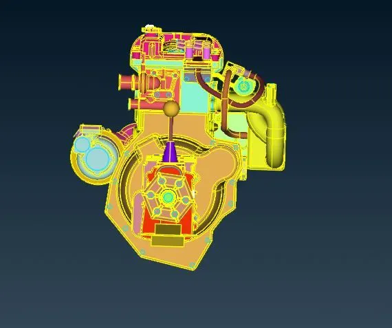
v. Generate surface wrap :-
For generating surface wrap go to mesh deck first and select (Element > Wrap>Constant length) as shown in image.
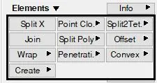
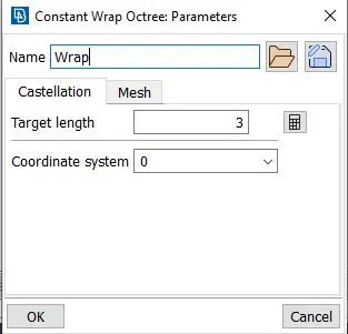
Here we take constant length because we want wrap of constant target length 3 mm.
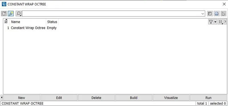
Double click on 'Empty' and we can see the windows shown below.
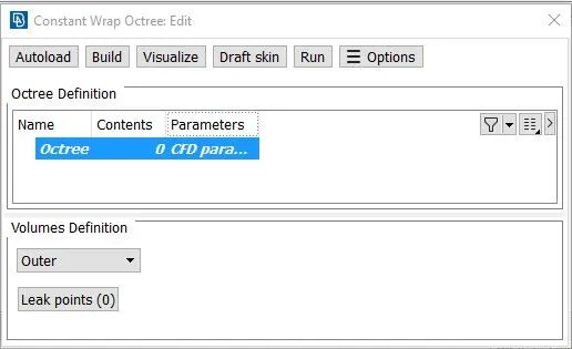
Double click on Parameters and we can see the window looks like below. Put the Tareget length as 3 mm and click on OK button.

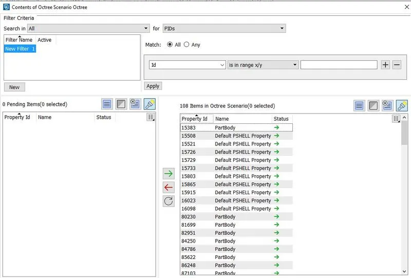
Now double click on Contents and we can see the window shown below. Select all the pending items and transfer into octree scenario and click on OK.
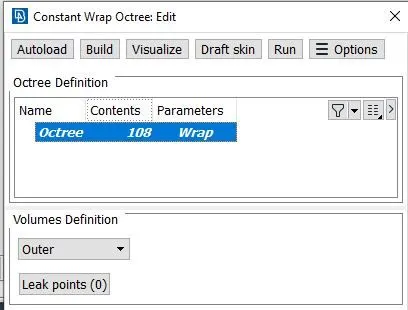
After assigning contents and parameters it looks like shown below and click on the 'Run'.
We get the surface wrap looks like shown below.
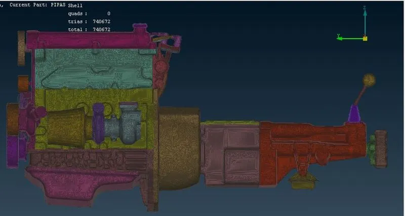
Conclusion :-
Here we have cleaned the geometries first and then assemble them. We fill the holes presrnt in the whole geometry and make a one common volume inside the geometry. We have assigned the target length as 3mm and perform the surface wrap over the geometry.