Week 5 Challenge
1. Basic design data:-
1.1 Span and Cross-section Data
C/C of expansion gap (Left Span) = 13.30 m (Sq.)
C/C of bearing (Left Span) = 12.30 m (Sq.)
Girder overhang beyond bearing (Left Span) = 0.35 m (Sq.)
Distance of bearing to expansion gap (Left span) = 0.5 m (Sq.)
C/C of expansion gap (Right Span) = 13.30 m (Sq.)
C/C of bearing (Right Span) = 12.30 m (Sq.)
Girder overhang beyond bearing (Left Span) = 0.35 m (Sq.)
Distance of bearing to expansion gap (Right span) = 0.5 m (Sq.)
Carriageway width = 11.00 m
Total width = 12.00 m
2. Superstructural details
No of longitudinal girders = 4
C/c spacing of longitudinal girders = 3.00
Footpath Width (Left side) = 0.00 m
Footpath Width (Right side) = 0.00 m
Crash Barrier Width (Left side) = 0.50 m
Crash Barrier Width (Right side) = 0.50 m
CG of crash barrier = 0.373 m
Handrail Width (Left side) = 0.00 m
Handrail Width (Right side) = 0.00 m
Wearing Coat Thickness = 0.065 m
Depth of superstructure (Left Span) = 1.320 m
Depth of superstructure (Right Span) = 1.320 m
CG of the superstructure from the bottom (Left Span) = 0.88 m
CG of the superstructure from the bottom (Right Span) = 0.88 m
Height of crash barrier = 0.90 m
Bearing thickness (Max) = 0.07 m
Height of pedestal = 0.25 m (Min.)
Expansion joint = 0.04 m
Superelevation/camber = 2.50%
Type of superstructure = RCC Girder and Dec+$AH$19k
Skew Angle = 0.00 o 0.000 radians
3. Salient Levels For design purposes only
Height of Substructures = 10 m
Finished Road Level FRL = 230.115 m
Bearing Level (Avg) BRL = 228.458 m
Pier Cap Top Level CTL = 2227.393 m
Footing top Level FTL = 217.262 m
Footing bottom Level FBL = 216.262 m
Lowest Bed Level LBL = 224.178 m
Maximum Scour Level MSL = 218.262 m
Highest Flood Level HFL = 227.105 m
Lowest Water Level LWL = 224.178 m
Founding Level (Actual) FL = 216.262 m
Founding Level (Design) FL = 216.262 m
Clear cover for foundation = 75 mm
4.Water Current Data
Max. mean velocity = 0.98 m/s
Constant "K" for the pier in transverse direction = 0.66
Constant "K" for the pier in the longitudinal direction = 1.5 (Cl. 210.2, IRC:6-2014)
% of Uplift Considered = 100 %
5.Material Data
For Pier cap, pier and Footing
Grade of concrete fck = M35
The design strength of concrete fcd 15.63 MPa
Modulus of Elasticity of steel Es = 2.0E+05 MPa
Modulus of Elasticity of Concrete Ec = 3.2E+04 MPa
Mean tensile strength of concrete fctm = 2.8 MPa
Grade of steel fyk = Fe500
The design strength of steel fyd 434.8 MPa
The density of concrete (RCC & PCC) conc_dens = 2.5 t/m3 (Cl.203 (6), IRC 6 2010)
Density of wearing course = 2.2 t/m3
Coefficient of Thermal Expansion of concrete = 1.2E-05 /oC (Cl.215.4, IRC 6 2010)
Shrinkage strain for concrete = 2.0E-04 (Cl.217.3, IRC 6 2010)
6. Soil Data
Density of soil = 2.0 t/m3
Submerged Density of soil = 1.0 t/m3
Type of soil = Medium Soil
Net safe bearing capacity at founding level = 25 t/m2
Gross SBS seicmic case (LWL) = 33.92 t/m3
Gross SBS seicmic case (HFL) = 27 t/m3
7.Load on Superstructure
Total Weight of structure =199 t
Dead Load reaction of span = 99.5 t
Total reaction on Pier= 199 t
Unbalanced long moment = 0
The transverse eccentricity of DL from Pier C /L = 0
Transverse moment due to unbalanced DL =0
SIDL (EXPECT WC)
Weight of Crash barrier =1 t/m
Weight of Crash barrier = 26.6 t
Weight of median =13.3 t
Weight of footpath =19.96 t
Total Reaction on Pier =54.86 t
Total Long Moment = 0 tm
The transverse eccentricity of CB =0 m
The transverse eccentricity of Median = 3.75 m
Transverse Moment of Median = 49.88 tm
Transverse Ecc. of Foothpath =4.75 m
Transverse Moment of FP = 71.07 tm
Total Transverse Moment =120.95 tm
SIDL (WC)
Load Intensity due to WC = 0.22 t/m2
Weight of WC = 26.33 t/m2
The intensity of FPLL 500 kg/m2
FPLL = 0.5 t/m2
FPLL =9.98 t
Unbalanced long Moment = 0
Transverse moment due to Unbalanced WC =52.67 tm
Substructure
Pier Cap (Rectangular Part)
Rectangular Part
Length = 10.10 m
Width = 2.20 m
Height = 0.25 m
Volume = 5.555 m3
Weight =13.89 t
Pier Cap (Trapezoidal Part)
Length (Top) = 10.1 m
Width (Top) = 2.2 m
Length (Bottom) = 8.5 m
Width (Bottom) = 0.6 m
Height = 0.50 m
Volume = 6.33 m3
Weight = 15.8 t
Total weight of pier cap = 29.7 t
Pier Shaft
Dimension along With Traffic = 0.7 m
Dimension Perpendicular To Traffic = 8.5 m
Area of cross-section of rectangular part = 5.95 m2
Height = 10.13 m
Volume = 60.28 m3
Nos. = 1
Area of cross-section of semi-circular part = 0.192 m2
Height = 10.13 m
Volume 3.9 m3
Weight = 160.44 t
Total Weight of Substructure = 190.15 t
Nos. = 2
Foundation
Type of foundation = open
Width of footing (long Dir.) = 6.5 m
Width of Footing (Transverse Dir.) = 9.4 m
The thickness of footing at the top =1 m
The Thickness of footing at the end =0.3 m
Volume rectangular =18.33 m3
Volume traperzodidal =20.09 m3
The total volume of footing =38.42 m3
Total Weight of footing = 96.05 t
Calculation of Weight of Soil on FOOTING
LWL Case
Bed Level = 224.178 m
Footing Bottom Level = 216.262 m
Weight =6.5 m
Lenght= 9.4 m
Average Height of Footing = 7.92 m
Total Volume = 483.668 m3
Volume of earth = 445.912 m3
Weight of Earth = 890.5 t
HFL Case with maximum scour
Volume of earth = 445.25 m3
Weight of Earth = 445.25 t
Water Current in Transverse Direction
Velocity through the vent = 0.98 m/sec
HFL =227.15 m
Source level =218.26 m
Pier bottom level =217.26 m
Founding level =216.26
Length level =13.55 m
Width of Pier =0.8 m
Constant K in transverse direction =0.66
Constant K in longitudinal direction =1.5
The intensity of water current pressure =52 k V2 kg / m2
= 149.8224 kg / m2
Velocity in Transverse direction= V max x cos 20 (Assuming 20-degree variation in water current direction)
Velocity in Longitudinal direction = 2 * v
Mean velocity of flow =0.980 m/s
Therefore, Vmax =1.386bm/s
Water Current in Transverse Direction
Force on the pier:
Submerged height of pier = 8.843 m
The intensity of pressure at the pier bottom level = 0.000 t/m2
Diameter of circular pier = 0.7 m
Force on a pier in transverse direction = 0.2 t
Transverse moment due to force on a pier at pier bottom = 1.4 t-m
Water Current in 20o from Transverse Direction Force on a pier
Force on a pier in transverse direction = 0.2 t
Transverse moment due to force on a pier at pier bottom = 1.2 t-m
Dia of circular pier = 0.7 m
Force on a pier in longitudinal direction = 0.1 t
Longitudinal moment due to force on a pier at pier bottom = 0.4 t-m
Force Summary due to Water (@pier top)
| Load case |
Load P t |
Load (Min) t |
ML tm |
MT tm |
HL t |
HT t |
| Water Current 0 degree | 0 | 0 | 0 | 1.4 | 0 | 0.2 |
| Water Current 20 degree | 0 | 0 | 0.4 | 1.2 | 0.1 | 0.2 |
Force Summary due to Water (@Footing bottom)
| Load case |
Load P t |
Load (Min) t |
ML tm |
MT tm |
HL t |
HT t |
| Water Current 0 degree | 0 | 0 | 0 | 1.6 | 0 | 0.2 |
| Water Current 20 degree | 0 | 0 | 0.4 | 1.2 | 0.1 | 0.2 |
Maximum Reaction Case
Left Side Span (C/C of Exp. Gap) = 13.3 m
Right Side Span (C/C of Exp. Gap) =13.3 m
Left Side Dist. Between Exp Gap & Bearing = 0.5 m
Right Side Dist. Between Exp Gap & Bearing =0.5 m
Left Side Span (C/C of Bearing) =12.3 m
Right Side Span (C/C of Bearing) =12.3
The train of loads are placed in such a way that CG of the load system is at the centre line of the pier to get the max reaction.
R1 =490 x { 12.3 - ( 2.658 + 0.666 - 0.5 ) } / ( 12.3 ) =377.5 kn
R3 = 490 - 377.5 =112.5KN
R2 = 510 x { 12.3 - ( 1.93 + 0.704 - 0.5 ) } / ( 12.3 ) =42.52 KN
R4 = 510 - 421.52 = 88.48 KN
Total Reaction on pier = 377.5 + 421.52=799.02 KN
Longitudinal Moment =(421.52 - 377.5 ) * 0.5=22.01 KN
Braking Force for LHS=0.2 * 490=98 KN
Braking Force for RHS =0.2 * 510=102 KN
1 Lane Class A:
R1=272 x { 12.3 - ( 4.5 + 0.708 - 0.5 ) } / ( 12.3 ) =799.02KN
R3=272 - 167.89=22.01KN
R2=282 x { 12.3 - ( 1.432 + 3.592 - 0.5 ) } / ( 12.3 ) =98KN
R4=282 - 178.28 =103.72KN
Total Reaction on pier=167.89 + 178.28=346.17 KN
Longitudinal Moment =(178.28 - 167.89) * 0.5=5.2 KN
Braking Force for LHS=0.2 * 272=54.4 KN
Braking Force for RHS =0.2 * 282=56.4 KN
2 Lane Class A:
For Class A 2 Lane the loads & the moments shall be multiplied by 2 times that of Class A 1 Lane.
R1=2 x 167.89=335.78KN
R3=2 x 104.11=208.22KN
R2=2 x 178.28=356.56KN
R4=2 x 103.72=207.44KN
Total Reaction on pier=335.56+356.56=692.34 KN
Longitudinal Moment =(356.56 - 335.78) * 0.5=10.39 KN
Braking Force for LHS=0.2 * 272=54.4 KN
Braking Force for RHS =0.2 * 282=56.4 KN
Calculation of Wind Forces on Superstructure
Height of crash barrier =0,5 m
Widht of superstructure =12m
h= clear height of pier = 10.13m
overall depth of superstructure 1.32
Transverse wind load =Fx=Pz*At*G*Cd
Wind Velocities & Pressure
PZ= 1064.5
VZ=42.1
Basic Wind Speed =50 m/s
Type of terrain =plain terrain
Wind load on DL+SIDL
Gust factor, G=2
CD=1.3
Exposed solid area=29.526
Transverse wind force =Fx=Pz*At*G*Cd
Transverse Wind force FDL=25%of =8.17
transverse wind force FID=2.04
Projected Area in Plan Producing Obstruction =159.6
Lift Coefficient, CL=0.75
Total Upward Wind Force on superstructure-25.48
Wind load on live load as per clause 209.4 of IRC:6
Basic wind speed is restricted to 36m/s as for the above speeds, it is considered that the deck is not carrying any live load on it. (Cl.209.3.7,IRC6:2014)
Distance of railing top from OGL=5.937
Type of terrain=Plian terrain
Wind speed=42.1
Wind load on substructure as per CL.209.4 of IRC6:2014
Pier cap:
Area of pier cap exposed to wind above GL in m2=125 m2
Avg height of pier cap from the top of GL=3.66 m2
The ratio of thickness to breadth,t/b=4.498
The ratio of height to breadth,h/b=0.33
The drag coefficient for the pier cap from Table-6 CD=1.2
Transverse wind force, FT=Fx=Pz*At*G*Cd
Transverse wind force, FT Force at pier bottom level=0.319 t
|
Force at pier bottom level |
||
|
HL wind |
Ftxsin(theta) |
0 |
|
HT wind |
Ft x cos(theta) |
1 |
|
ML |
0 |
|
|
MT |
10.4 |
Force at footing bottom level
|
Force at pier bottom level |
||
|
HL wind |
Ftxsin(theta) |
0 |
|
HT wind |
Ft x cos(theta) |
1 |
|
ML |
0 |
|
|
MT |
11.4 |
Pier
Area of pier cap exposed to wind above GL in m2=6.4m2
Avg height of pier cap from the top of GL[=9.13 m2
The ratio of thickness to breadth,t/b=12.14
The ratio of height to breadth,h/b=13.04
The drag coefficient for the pier cap from Table-6 CD=1.2
Wind load on substructure as per CL.209.4 of IRC6:2014
PZ=1064.5N/m2
VZ=50 m/s
Transverse wind force, FT =Fx=Pz*At*G*Cd
Transverse wind force, FT=1
|
Force at pier bottom level |
||
|
HL wind |
Ftxsin(theta) |
0 |
|
HT wind |
Ft x cos(theta) |
6.1 |
|
ML |
0 |
|
|
MT |
69.9 |
|
Force at footing bottom level |
||
|
HL wind |
Ftxsin(theta) |
0 |
|
HT wind |
Ft x cos(theta) |
6.1 |
|
ML |
0 |
|
Forces at the pier bottom level |
||||||
|
Load case |
Load (max) |
Load (min) |
ML |
MT |
HL |
HT |
|
t |
t |
tm |
tm |
tm |
tm |
|
|
Wind |
-25.48 |
-25.48 |
22.9 |
171.8 |
2.04 |
8.17 |
BASE PRESSURE CHECK
Area of footing = 6.1 m2
Section modulus about transverse Axis ,ZLL= (L*B2)/6=66.19 m3
Section modulus about long. Axis ,ZTT= 95.72 m3
Gross SBC =32.92 t/m2
| Load | Pmax | Pmin | ML | MT | HL | HT |
|
DL |
199 | 199 | 0 | 0 | 0 | 0 |
| SDL | 54.86 | 54.86 | 0 | 120.95 | 0 | 0 |
| Wearing Coat | 26.33 | 26.33 | 0 | 53 | 0 | 0 |
| LL | 94.22 | 94.22 | 91 | 179.49 | 9.42 | 0 |
| FPLL | 9.98 | 9.98 | 0 | 0 | 0 | 0 |
| Weight of substructure | 190.15 | 190.15 | 0 | 0 | 0 | 0 |
| Weight of footing | 96.05 | 96.05 | 0 | 0 | 0 | 0 |
|
Weight of soil above footing |
890.5 | 890.5 | 0 | 0 | 0 | 0 |
|
Wind load |
-25.48 | -25.48 | 22.9 | 171.8 | 2.04 | 8.17 |
|
Water Current (0) |
0 | 0 | 0 | 1.6 | 0 | 0.2 |
|
Water Current (20) |
0 | 0 | 0.4 | 1.4 | 0 | 0.2 |
|
Total Load |
1535.6 | 1535.6 | 114.3 | 527.9 | 11.56 | 8.57 |
LOAD COMBINATION
Combination for base pressure
p1= (P/A)+[(ML/ZL)+(MT/ZT)=32.37
p2= (P/A)+[(ML/ZL)-(MT/ZT)=21.34
p3= (P/A)-[(ML/ZL)-(MT/ZT)=17.89
p4= (P/A)-[(ML/ZL)+(MT/ZT) =28.92
Summary
Force@ bearing level
| Load case |
Load P t |
Load (Min) t |
ML tm |
MT tm |
HL t |
HT t |
| DL | 199 | 199 | 0 | 0 | 0 | 0 |
| SIDL | 54.86 | 54.86 | 0 | 120.95 | 0 | 0 |
| SIDL(WL) | 26.33 | 26.33 | 0 | 53 | 0 | 0 |
Force@ pier bottom level
| Load case |
Load P t |
Load (Min) t |
ML tm |
MT tm |
HL t |
HT t |
| DL | 199 | 199 | 0 | 0 | 0 | 0 |
| SIDL | 54.86 | 54.86 | 0 | 120.95 | 0 | 0 |
| SIDL(WL) | 26.33 | 26.33 | 0 | 53 | 0 | 0 |
Force@ pier cap bottom level
| Load case |
Load P t |
Load (Min) t |
ML tm |
MT tm |
HL t |
HT t |
| DL | 199 | 199 | 0 | 0 | 0 | 0 |
| SIDL | 54.86 | 54.86 | 0 | 120.95 | 0 | 0 |
| SIDL(WL) | 26.33 | 26.33 | 0 | 53 | 0 | 0 |
One span dislodged Condition
DL of superstructure =99.5 t
Long Moment SIDL(With WC) = 49.75 tm
Load Pier =27.43 t
Long. Moment =13.72 tm
Transverse Moment SIDL(WC)= 0
Load Pier = 13.17 t
Long. Moment =6.58 tm
Transverse Moment = tm
Forces at bearing level
| Load case |
Load P t |
Load (Min) t |
ML tm |
MT tm |
HL t |
HT t |
| DL | 99.5 | 99.5 | 49.75 | 0 | 0 | 0 |
| SIDL | 27.43 | 27.43 | 13.72 | 0 | 0 | 0 |
| SIDL(WL) | 13.17 | 13.17 | 6.58 | 0 | 0 | 0 |
Forces at pier top level
| Load case |
Load P t |
Load (Min) t |
ML tm |
MT tm |
HL t |
HT t |
| DL | 99.5 | 99.5 | 49.75 | 0 | 0 | 0 |
| SIDL | 27.43 | 27.43 | 13.72 | 0 | 0 | 0 |
| SIDL(WL) | 13.17 | 13.17 | 6.58 | 0 | 0 | 0 |
Forces at pier cap level
| Load case |
Load P t |
Load (Min) t |
ML tm |
MT tm |
HL t |
HT t |
| DL | 99.5 | 99.5 | 49.75 | 0 | 0 | 0 |
| SIDL | 27.43 | 27.43 | 13.72 | 0 | 0 | 0 |
| SIDL(WL) | 13.17 | 13.17 | 6.58 | 0 | 0 | 0 |
Combination of loads for design of foundation
Footing bottom level
Both span present
|
Loads |
Factors |
Un factored |
Factored |
||||||||||
|
|
Pmax |
Pmin |
ML |
MT |
HL |
HT |
Pmax |
Pmin |
ML |
MT |
HL |
HT |
|
|
DL |
1.35 |
199 |
199 |
0 |
0 |
0 |
0 |
268.65 |
268.65 |
0 |
0 |
0 |
0 |
|
SDL |
1.35 |
54.86 |
54.86 |
0 |
0 |
0 |
0 |
74.061 |
74.061 |
0 |
0 |
0 |
0 |
|
Wearing coat |
1.75 |
26.33 |
26.33 |
0 |
0 |
0 |
0 |
46.0775 |
46.0775 |
0 |
0 |
0 |
0 |
|
LL-Leading |
1.5 |
94.22 |
94.22 |
91 |
179.49 |
9.42 |
0 |
141.33 |
141.33 |
136.5 |
269.235 |
14.13 |
0 |
|
LL-Accompaning |
1.15 |
75.03 |
75.03 |
72.47 |
142.93 |
7.5 |
0 |
86.2845 |
86.2845 |
83.3405 |
164.3695 |
8.625 |
0 |
|
FPLL |
1.15 |
9.98 |
9.98 |
0 |
0 |
0 |
0 |
11.477 |
11.477 |
0 |
0 |
0 |
0 |
|
Weight of substructure |
1.35 |
190.15 |
190.15 |
0 |
0 |
0 |
0 |
256.7025 |
256.7025 |
0 |
0 |
0 |
0 |
|
Footing Weight |
1.35 |
96.05 |
96.05 |
0 |
0 |
0 |
0 |
129.6675 |
129.6675 |
0 |
0 |
0 |
0 |
|
Weight of soil above the footing |
1.35 |
890.5 |
890.5 |
0 |
0 |
0 |
0 |
1202.175 |
1202.175 |
0 |
0 |
0 |
0 |
|
Wind loading |
1.5 |
-25.48 |
-25.48 |
22.9 |
171.8 |
2.04 |
8.17 |
-38.22 |
-38.22 |
34.35 |
257.7 |
3.06 |
12.255 |
|
Wind accompanying |
0.9 |
-25.48 |
-25.48 |
22.9 |
171.8 |
2.04 |
8.17 |
-22.932 |
-22.932 |
20.61 |
154.62 |
1.836 |
7.353 |
|
LL -Leading |
Total |
2068.97 |
2068.97 |
191.46 |
681.55 |
19.04 |
19.61 |
|
LL-accompanying |
Total |
2013.93 |
2013.93 |
138.3 |
576.69 |
13.53 |
19.61 |
The rare combination of loads
Footing bottom level
Both span present
|
Loads |
Factors |
Un factored |
Factored |
||||||||||
|
|
Pmax |
Pmin |
ML |
MT |
HL |
HT |
Pmax |
Pmin |
ML |
MT |
HL |
HT |
|
|
DL |
1 |
199 |
199 |
0 |
0 |
0 |
0 |
199 |
199 |
0 |
0 |
0 |
0 |
|
SDL |
1 |
54.86 |
54.86 |
0 |
0 |
0 |
0 |
54.86 |
54.86 |
0 |
0 |
0 |
0 |
|
Wearing coat |
1.2 |
26.33 |
26.33 |
0 |
0 |
0 |
0 |
31.596 |
31.596 |
0 |
0 |
0 |
0 |
|
LL-Leading |
1 |
94.22 |
94.22 |
91 |
179.49 |
9.42 |
0 |
94.22 |
94.22 |
91 |
179.49 |
9.42 |
0 |
|
LL-Accompaning |
0.75 |
75.03 |
75.03 |
72.47 |
142.93 |
7.5 |
0 |
56.2725 |
56.2725 |
54.3525 |
107.1975 |
5.625 |
0 |
|
FPLL |
0.75 |
9.98 |
9.98 |
0 |
0 |
0 |
0 |
7.485 |
7.485 |
0 |
0 |
0 |
0 |
|
Weight of substructure |
1 |
190.15 |
190.15 |
0 |
0 |
0 |
0 |
190.15 |
190.15 |
0 |
0 |
0 |
0 |
|
Footing Weight |
1 |
96.05 |
96.05 |
0 |
0 |
0 |
0 |
96.05 |
96.05 |
0 |
0 |
0 |
0 |
|
Weight of soil above footing |
1 |
890.5 |
890.5 |
0 |
0 |
0 |
0 |
890.5 |
890.5 |
0 |
0 |
0 |
0 |
|
Wind leading |
1 |
-25.48 |
-25.48 |
22.9 |
171.8 |
2.04 |
8.17 |
-25.48 |
-25.48 |
22.9 |
171.8 |
2.04 |
8.17 |
|
Wind accompanying |
0.6 |
-25.48 |
-25.48 |
22.9 |
171.8 |
2.04 |
8.17 |
-15.288 |
-15.288 |
13.74 |
103.08 |
1.224 |
4.902 |
|
LL -Leading |
Total |
1523.08 |
1523.08 |
127.64 |
454.37 |
12.69 |
13.08 |
|
LL-accompanying |
Total |
1485.13 |
1485.13 |
90.99 |
382.08 |
8.9 |
13.08 |
Base pressure for footing design
Area of footing A= L x B =61.10 m2
Section modulus about trans axis, ZLL= (L x B2)/6 = 66.19 m3
Section modulus about Loong axis, ZTT= (Bx L2)/6 =95.72 m3
Gross SBC (LWL)=32.92 t/m2
Both span Present
Factored loads for base pressure
|
|
Pmax |
Pmin |
ML |
MT |
HL |
HT |
|
LL -Leading |
2068.97 |
2068.97 |
191.46 |
681.55 |
19.04 |
19.61 |
|
LL-accompanying |
2013.93 |
2013.93 |
138.3 |
576.69 |
13.53 |
19.61 |
Combination for base pressure
LL-Leading
p1= (P/A)+[(ML/ZL)+(MT/ZT)=43.87 t/m2
p2= (P/A)+[(ML/ZL)-(MT/ZT)=29.63 t/m2
p3= (P/A)-[(ML/ZL)-(MT/ZT)=23.85 t/m2
p4= (P/A)-[(ML/ZL)+(MT/ZT) =38..09 t/m2
LL-Accompanying
p1= (P/A)+[(ML/ZL)+(MT/ZT)=41.08 t/m2
p2= (P/A)+[(ML/ZL)-(MT/ZT)=29.03 t/m2
p3= (P/A)-[(ML/ZL)-(MT/ZT)=24.85 t/m2
p4= (P/A)-[(ML/ZL)+(MT/ZT) =36.9 t/m2
Design of footing slab-Transverse Direction
Grade of concrete = M35
The design strength of concrete = 15.63
Grade of steel = Fe500
The design strength of steel =434.8
Modulus of elasticity of steel = 200000 Mpa
Modulus elasticity of concrete = 32000 Mpa
Cu = 0.8095*fcd*b*xu
Tu = (fy/1.15)*Ast
xu,lim/d = 0.617
Rlim= Mu,lim/bd2 = 0.8095fcd*(xu/d)*(1-0.416*xu/d) = 5.8 m
Overall depth of the section = 1m
The critical section for the moment is at the face of the column
The critical case for design
|
Gross pressure(t/m2) |
|||
|
p1 |
p2 |
p3 |
p4 |
|
43.87 |
29.63 |
23.85 |
38.09 |
|
Net pressure(t/m2) |
|||
|
p1 |
p2 |
p3 |
p4 |
|
27.8 |
13 |
7.7 |
22.5 |
Overhang h= 0.45 m
A1 =p1+p4*l/2 =236.41 t/m
A2 =p1+p2*l/2 = 187.06 t/m
volume =(A1+A2+sqrt(A1A2))*h/3 = 95.06 t
lever arm = h/4*(A1+2*sqrt(A1*A2)+3*A2)/(A1+sqrt(A1*A2)+A2) =0.22m
Design Moment,Mu =Volume*lever arm =20.91 tm
Equivalent width of rectangular section, b = b+1/8*(B-bt)= 1.425 m
R= 0.17
Effective depth required = sqrt(Mu/R*b) = 293.82 mm
Effective depth available = 917 mm
Area of steel required = 513 mm2
Dia of main reinforcement = 16 mm
Provide = 16 mm dia @ 125mm c/c
Area of steel provided = 1607.68 mm2 ok
Top reinforcement
Min % of steel =0.146
Area of steel required at the top =673 mm2
Provide = 12 mm dia @150 mm c/c
Checked for minimum and maximum reinforcement as per IRC 112
Base pressure for a rare combination
Base pressure for footing design
The critical section for a moment is at the face of the column
A critical case for design
|
Gross pressure(t/m2) |
|
||
|
p1 |
p2 |
p3 |
p4 |
|
43.87 |
29.63 |
23.85 |
38.09 |
|
Net pressure(t/m2) |
|||
|
p1 |
p2 |
p3 |
p4 |
|
27.8 |
13 |
7.7 |
22.5 |
Overhang h= 0.45 m
A1 =p1+p4*l/2 =236.41 t/m
A2 =p1+p2*l/2 = 187.06 t/m
volume =(A1+A2+sqrt(A1A2))*h/3 = 95.06 t
lever arm = h/4*(A1+2*sqrt(A1*A2)+3*A2)/(A1+sqrt(A1*A2)+A2) =0.22m
Design Moment,Mu =Volume*lever arm =20.91 tm
Equivalent width of rectangular section, b = b+1/8*(B-bt)= 1.425 m
R= 0.17
Effective depth required = sqrt(Mu/R*b) = 293.82 mm
Effective depth available = 917 mm
Area of steel required = 513 mm2
Dia of main reinforcement = 16 mm
Provide = 16 mm dia @ 125mm c/c
Area of steel provided = 1607.68 mm2 ok
Top reinforcement
Min % of steel =0.146
Area of steel required at the top =673 mm2
Provide = 12 mm dia @150 mm c/c
Checked for minimum and maximum reinforcement as per IRC 112
Base pressure for the rare combination
Base pressure for footing design
Area of footing A= L x B =61.10 m2
Section modulus about trans axis, ZLL= (L x B2)/6 = 66.19 m3
Section modulus about Loong axis, ZTT= (Bx L2)/6 =95.72 m3
Gross SBC (LWL)=32.92 t/m2
Both span Present
Factored loads for base pressure
|
|
Pmax |
Pmin |
ML |
MT |
HL |
HT |
|
LL -Leading |
1523.08 |
1523.08 |
127.64 |
454.37 |
12.69 |
13.08 |
|
LL-accompanying |
1485.13 |
1485.13 |
90.99 |
382.08 |
8.9 |
13.08 |
Combination for base pressure
LL-Leading
p1= (P/A)+[(ML/ZL)+(MT/ZT)=31.6 t/m2
p2= (P/A)+[(ML/ZL)-(MT/ZT)=22.11 t/m2
p3= (P/A)-[(ML/ZL)-(MT/ZT)=18.25t/m2
p4= (P/A)-[(ML/ZL)+(MT/ZT) =27.75 t/m2
LL-Accompanying
p1= (P/A)+[(ML/ZL)+(MT/ZT)=29.67 t/m2
p2= (P/A)+[(ML/ZL)-(MT/ZT)=21.69 t/m2
p3= (P/A)-[(ML/ZL)-(MT/ZT)=18.94 t/m2
p4= (P/A)-[(ML/ZL)+(MT/ZT) =26.92 t/m2
Design of footing for SLS
Overall depth of the section
The critical case for design
|
Gross pressure(t/m2) |
|||
|
p1 |
p2 |
p3 |
p4 |
|
31.6 |
22.11 |
18.25 |
27.75 |
|
Net pressure(t/m2) |
|||
|
p1 |
p2 |
p3 |
p4 |
|
15.4 |
5.6 |
2.1 |
11.9 |
Overhang h= 0.45 m
A1 =p1+p4*l/2 =128.6 t/m
A2 =p1+p2*l/2 = 126.3 t/m
volume =(A1+A2+sqrt(A1A2))*h/3 = 57.35 t
lever arm = h/4*(A1+2*sqrt(A1*A2)+3*A2)/(A1+sqrt(A1*A2)+A2) =0.22m
Design Moment,Mu =Volume*lever arm =12.62 tm
Equivalent width of rectangular section, b = b+1/8*(B-bt)= 1.425 m
Calculation of stress in concrete
Permissible stress in concrete = 0.48fck= 16.8 Mpa
Permissible stress on raft = 0.8fyk = 400 Mpa
Design moment per unit width 1.98 tm/m
Modular ratio =6.25
width = 1 m
Ast Provided =1607.68 mm2/m
Eff Depth = 917 mm
NA depth = 126.6 mm
Eff moment of inertia = 7.08*10^9 mm4
Section modulus of concrete = 5.59*10^7 mm3
Section modulus of reinforcement = 8.87*10^6 mm3
Stress in concrete = 0.35 Mpa ok
Stress in reinforcement = 13.94 Mpa ok
Design of footing slab -Longitudinal Direction
Grade of concrete =M35
The design strength of concrete =15.63
Grade of steel =Fe500
The design strength of steel =434.8
Modulus of elasticity of concrete =32000Mpa
Modulus of elasticity of steel =200000Mpa
Overall depth of section = 1m
The critical section for the moment is at the face of the column
|
Gross pressure(t/m2) |
|||
|
p1 |
p2 |
p3 |
p4 |
|
43.87 |
29.63 |
23.85 |
38.09 |
|
Net pressure(t/m2) |
|
||
|
p1 |
p2 |
p3 |
p4 |
| 27.8 |
13 |
7.7 |
22.5 |
Overhang h= 0.45 m
A1 =p1+p4*l/2 =191.6 t/m
A2 =p1+p2*l/2 = 169.5 t/m
volume =(A1+A2+sqrt(A1A2))*h/3 = 523.2 t
lever arm = h/4*(A1+2*sqrt(A1*A2)+3*A2)/(A1+sqrt(A1*A2)+A2) =1.42 m
Design Moment,Mu =Volume*lever arm =742.94 tm
Equivalent width of rectangular section, b = b+1/8*(B-bt)= 8.61 m
Effective depth required = sqrt(Mu/R*b) = 292.25 mm
Effective depth available = 917 mm
Area of steel required = 19132.83 mm2
Dia of main reinforcement = 25 mm
Provide = 25 mm dia @ 125mm c/c
Area of steel provided = 3925 mm2 ok
Top reinforcement
Min % of steel =0.146
Area of steel required at the top =673 mm2
Provide = 12 mm dia @150 mm c/c
Checked for minimum and maximum reinforcement as per IRC 112
Design of footing slab-SLS
Longitudinal Direction
Overall depth of the section = 1m
Critical depth of the section
|
Gross pressure(t/m2) |
|||
|
p1 |
p2 |
p3 |
p4 |
|
31.6 |
22.11 |
18.25 |
27.75 |
|
Net pressure(t/m2) |
|
||
|
p1 |
p2 |
p3 |
p4 |
| 15.4 | 5.6 |
2.1 |
11.9 |
Overhang h= 2.9 m
A1 =p1+p4*l/2 =68.3 t/m
A2 =p1+p2*l/2 = 58.1 t/m
volume =(A1+A2+sqrt(A1A2))*h/3 = 183.2 t
lever arm = h/4*(A1+2*sqrt(A1*A2)+3*A2)/(A1+sqrt(A1*A2)+A2) =1.41 m
Design Moment,Mu =Volume*lever arm =258.31 tm
Equivalent width of rectangular section, b = b+1/8*(B-bt)= 8.61 m
Calculation of stress in concrete
Permissible stress in concrete = 0.48fck= 16.8 Mpa
Permissible stress on raft = 0.8fyk = 400 Mpa
Design moment per unit width 27.5 tm/m
Modular ratio =6.25
width = 1 m
Ast Provided =3925 mm2/m
Eff Depth = 917 mm
NA depth = 189.95 mm
Eff moment of inertia = 1.55*10^10 mm4
Section modulus of concrete = 8.18*10^7 mm3
Section modulus of reinforcement = 2.11*10^7 mm3
Stress in concrete = 3.36 Mpa ok
Stress in reinforcement = 81.26 Mpa ok
2. Difference between the free pier and fixed pier
The pier which supports a free bearing is called a free pier. In the case of a free pier transfer of axial forces only happens and movement in the longitudinal direction is allowed hence there are no longitudinal reactions. Hence horizontal forces such as braking load, surcharge, seismic load, and water pressure are not considered in a free pier. Because of less horizontal force, the size of the foundation is considerably less than the fixed pier.
The pier which supports a fixed bearing is called a fixed pier. In fixed pier, rotation and lateral movements are resisted and hence a large amount of transverse and longitudinal moments occur. All the horizontal and vertical forces are considered in the fixed pier. The size of the foundation of the fixed pier is large comparatively to accommodate the heavy forces.
Longitudinal force due to friction (CL.211.5.1 IRC 6)
For simply supported span with fixed bearing on stiff support, horizontal force at the bearing level in longitudinal direction shall be greater of the two values given below: -
Fh= Applied horizontal forces
Rg= Reaction at the free end due to dead load
Rq= Reaction at the free end due to live load
μ= Co-efficient of friction at movable bearing
One span loaded condition
Horizontal force = μ(Rh+Rq)
|
Left span |
Right span |
|
|
Rg |
140.1 t |
140.10 t |
|
Rq |
0 |
41.8 t |
|
μ |
0.03 |
0.05 |
|
Horizontal force dead load, μRg |
4.20 t |
7.00 t |
|
Horizontal force live load, μRq |
0 |
2.09 t |
Applied horizontal force Fh = 14.58 t
Fixed End
Total horizontal force= Maximum of the following two cases
Fh-μ(Rg+Rq) =10.38 t
Fh/2+μ(Rh+Rq) = 11.49 t
HL = 11.49 t
Free End
Total horizontal force
μ(Rg+Rq) = 4.20 t
HL = 4.20 t
Two-span loaded condition
Horizontal force = μ(Rh+Rq)
|
Left span |
Right span |
|
|
Rg |
140.1 t |
140.10 t |
|
Rq |
34.8 |
41.8 t |
|
μ |
0.03 |
0.05 |
|
Horizontal force dead load, μRg |
4.20 t |
7.00 t |
|
Horizontal force live load, μRq |
1.0 t |
2.09 t |
Applied horizontal force Fh = 21.87 t
Fixed End
Total horizontal force= Maximum of the following two cases
Fh-μ(Rg+Rq) =16.62 t
Fh/2+μ(Rh+Rq) = 16.18 t
HL = 16.62 t
Free End
Total Horizontal force
μ(Rg+Rq) = 5.25 t
HL =5.25 t
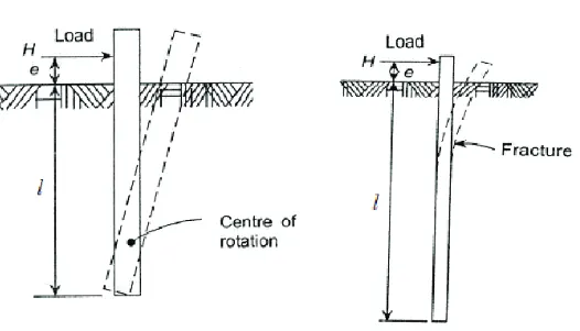
Free Head Fixed Head
3. RCC design checks to be done in the ultimate & serviceability state
ULS
This limit state includes static equilibrium and failure of structure when acted by ultimate design load.
- Limit state of strength
- Limit state of equilibrium
SLS
These limit state specifically deals with the condition of the structure subjected to the influence of serviceability design loads.
- Limit state of internal stress (Rare combination),” Stress in concrete can be controlled”.
- Limit state of crack control (Quasi permanent combination),” Crack control shall be considered. The allowable crack width is 0.3mm.
- Limit state of deformation.
- Limit state of vibration.
- Limit state of fatigue.