Week 5 Challenge
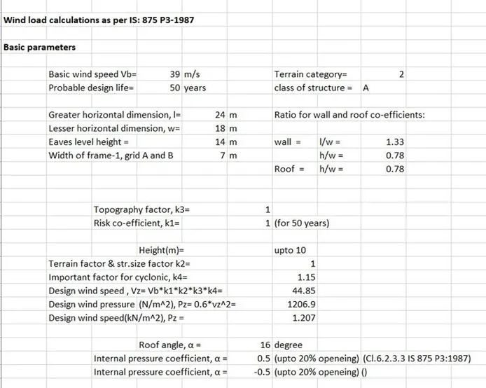
Q1 ) Generate manual wind loading in the design report based IS code as per the following input
- Basic wind speed = 39m/s
- Terrain category 2
ANS 1 :
AIM: Generate manual wind loading in the design report based IS code as per the following input
TOOLS USED :
- Excel.
- IS codes.
- Calculator.
PROCEDURE :
- First we have to open MS Excel (optional) to enter the values used for calculations.
- Next we have to obtain the required standard values from the IS codes.
- We have to have the dimensions of our project ( length, bredth and height)
- Assume the wind speed as 39 m/s.
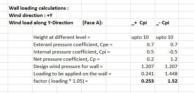
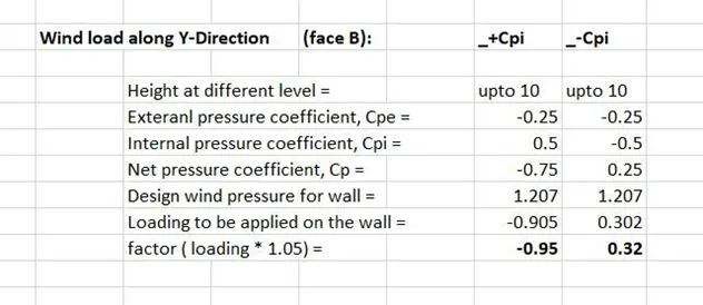
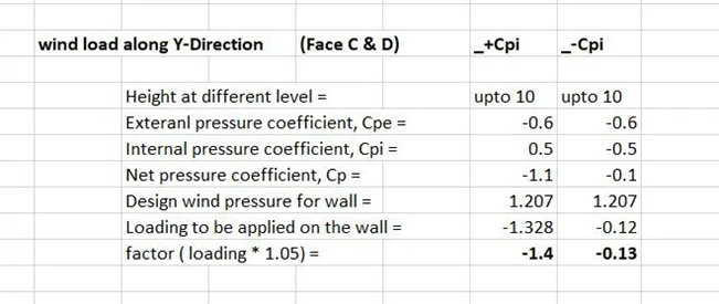
- Next we have to calculate the wind direction in both the X and Y direction ( +Cpi and -Cpi)
- We have to calculate :
- External pressure coefficients.
- Internal pressure coefficients.
- Net pressure coefficients.
- Design wind presssure for wall.
- Loading to be appplied on the wall.
RESULT :
Thus after we obtain all the above values, we can start our manual calculation.
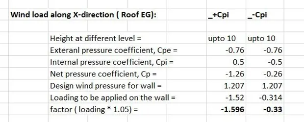
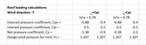
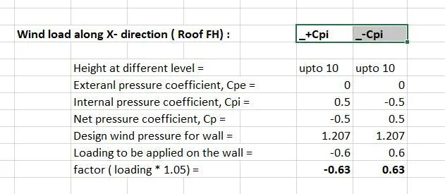
Q2 ) Based on the above calculation apply the loadings on the model
ANS 2 :
AIM : Based on the above calculation apply the loadings on the model
TOOLS USED :
- Loaads.
- Loadcases.
- Wind load.
- Area.
- Global X.
- Global Y.
- Global Z.
PROCEDURE :
- First open the file for which we have to apply the wind loads.
- Go to loadcases and add 8 wind loads :
- Wind + Y + Cpi
- Wind + Y - Cpi
- Wind - Y + Cpi
- Wind - Y - Cpi
- Wind + X + Cpi
- Wind + X - Cpi
- Wind - X + Cpi
- Wind - X - Cpi
- Next with the help of the manual loads which were calculated earlier, apply the loads on the structure.
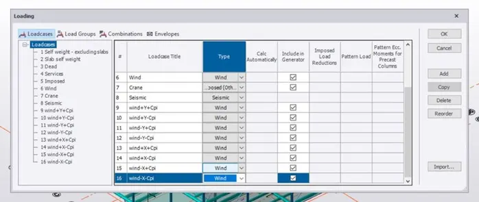
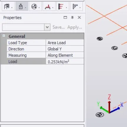
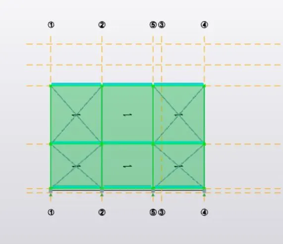
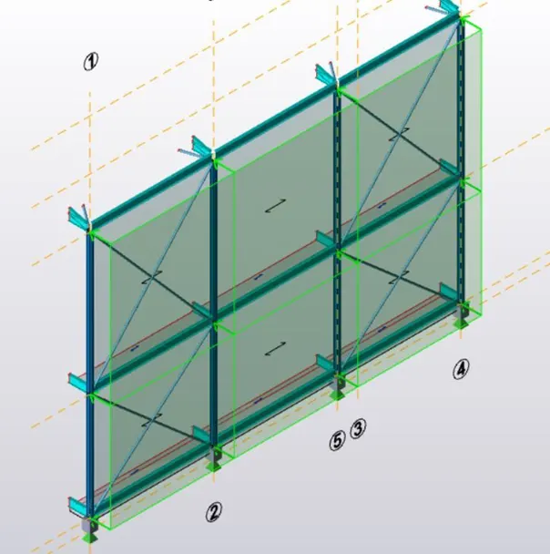
- Adjust the direction to global Y for face A and B.
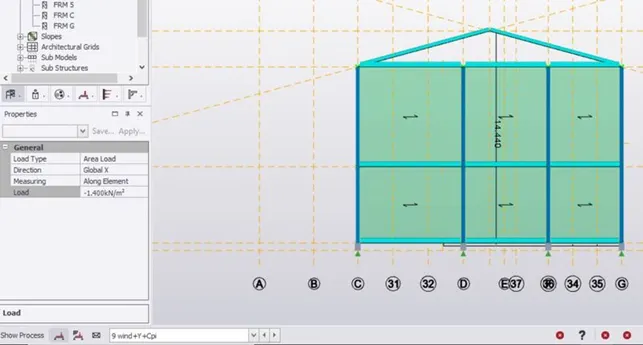
- Adjust the direction to global X for face C and D.
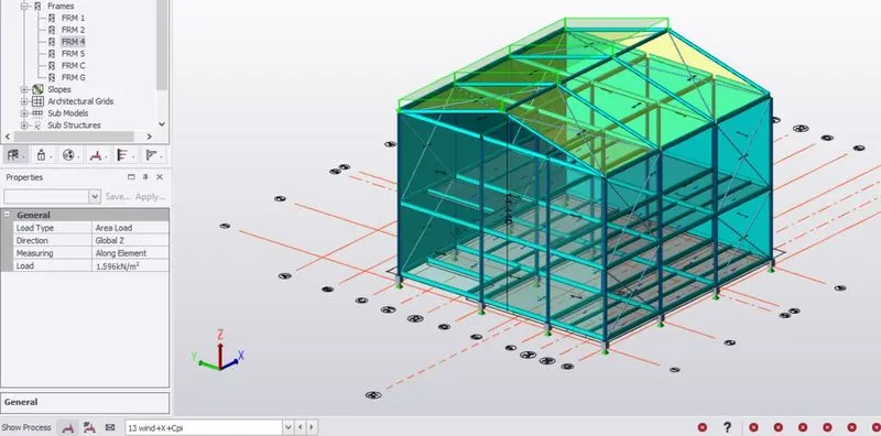
- Adjust the direction to global Z for the roof components.
- For all the sides we have to apply both +Cpi and -Cpi values.
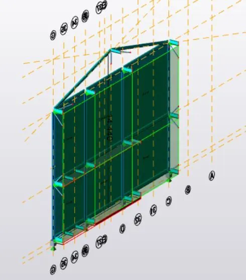
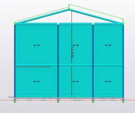
- With this all the loads can be applied on the structure.
RESULT :
With the above calculated loads, now they are applied on the structure.
Q3 ) On a separate model generate wind loading using wind wizard.
ANS 3 )
AIM : On a separate model generate wind loading using wind wizard
TOOLS USED :
- Manage property sets.
- Beams.
- Columns.
- Construction levels.
- Loadcases.
- Wall panels.
- Roof panels.
- Wind wizard.
- Frames.
PROCEDURE :
- Open a new file to start the drawing.
- Create construction levels with required height.
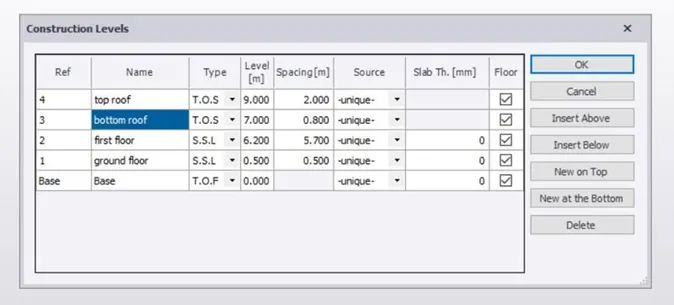
- Go to manage property sets and create new concrete columns, steel columns and beams. ( use different grade for required places)
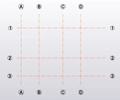
- Select the base and add concrete columns.
- Now
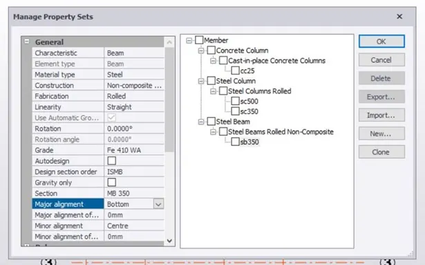 add steel beams from ground floor to first floor.
 - Add dead and live loads on the structure.
- Create frames for the structure.
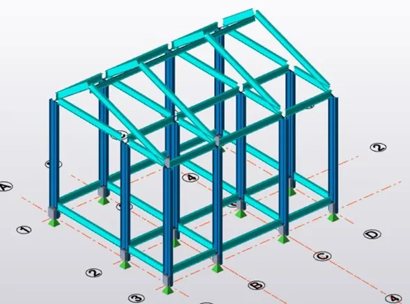
- Select the side view and construct the rafter using steel beams option.
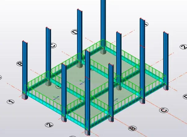
- Now design wall and roof panels for the structure.
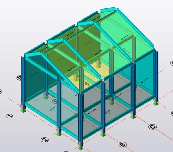
- Click on wind wizard option.
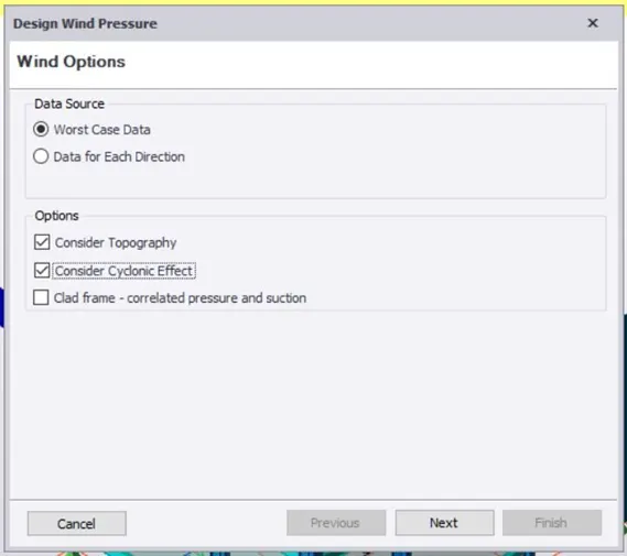
- Select consider topography and consider cyclonic effect options and click on next.
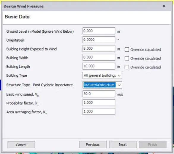
- Next give the dimensions and enter the wind speed value as 39 m/s. And select all general buildings and industrial structure.
- Select the terrain category and enter the fetch a distance value as 10m and click on next.
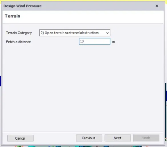
- The results will be appeared and click on next.
- At last click on finish option.
- Now we are successful in applying the wind loads using wind wizard tool.
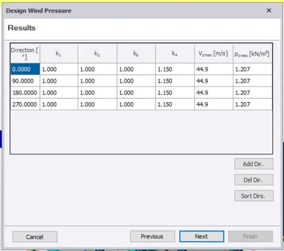
RESULT :
With the above steps we can complete wind analysis using wind wizard tool for automatic calculations.