Week 5 Bending of iPhone
Objective
- To perform a bending simulation of an iPhone in the Ansys workbench and to find out the result for the following cases.
Case 1: Simulate the model using default materials.
Case 2: Move the bottom fingers from their defined position to the given position X= 22.5mm & Z= 10mm and obtain the results for the simulation. Also, define the S-N curve for the Aluminium Alloy material as per values given below and determine the fatigue life results for the same.
Procedure
- Drag the static structural module onto the work page and import the model.
- Open the model in the space claim to check for any abnormality.
- From the engineering data, Glass, polyethylene, Aluminium alloy NL was added.
- Now the mechanical module can be opened for further setting up the model.
- The parts are renamed from the geometry tab and assigned materials to the corresponding parts.
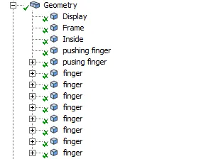
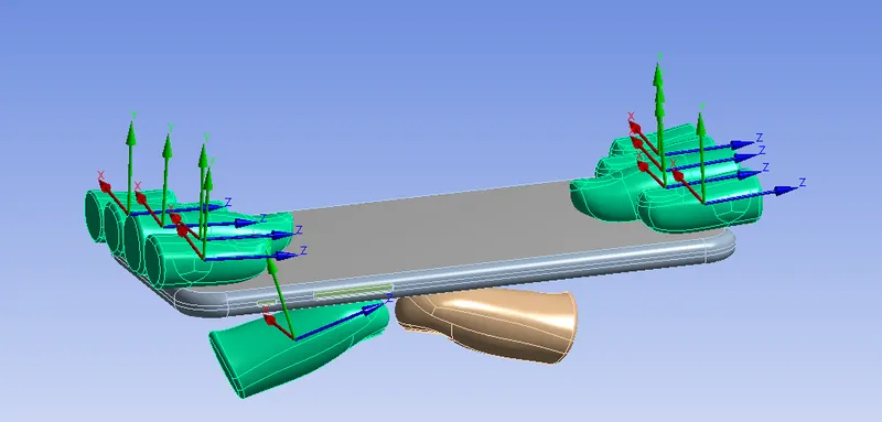
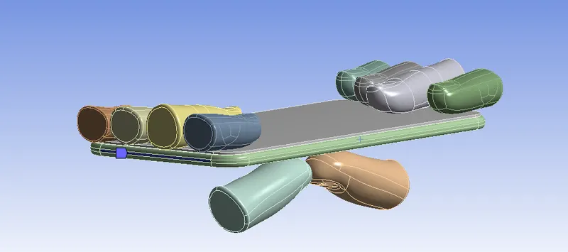
- From geometry, some fingers are selected and change the stiffness behavior to rigid as shown below.
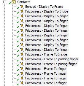
- There are lots of contacts detected automatically by the software and the unwanted contacts can be deleted. Select all the rest of the contacts and right-click>Rename based on the definition.
- Unselect the bonded display to frame contact and select all the other and change it to frictionless. Since the frame is going to be fixed with the display we must define it as bonded.
- A fixed joint is been given to all the fingers on the top part. Select one face of the finger>right click>hide all other bodies. This way we can isolate each part. From the connection, select body-ground>fixed. Click scope>use box select option>select all the faces of the finger and click apply. Similarly define it for all the other fingers at the top.
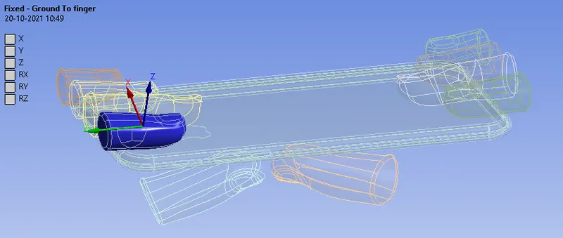
- The bottom fingers need to be provided with a translational joint. from the connection, select body-ground>translational. Click scope>use box select option>select all the faces of the finger and click apply. Expand the translational joint created and click the reference coordinate system to check the direction of the translational motion. The correction has to be made if required.
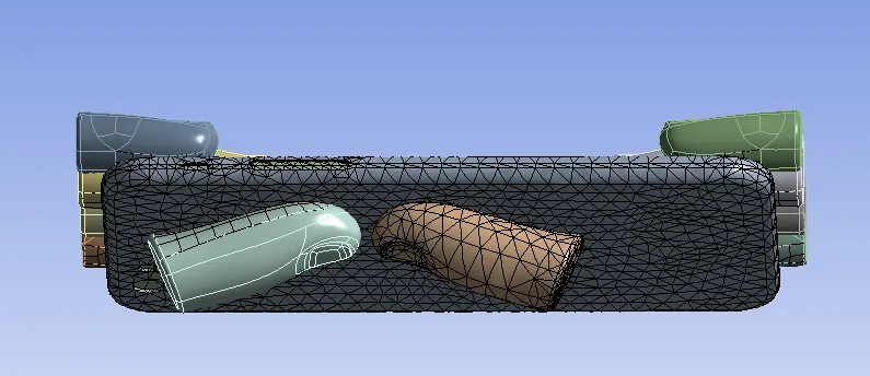
- For meshing the face sizing with an element size of 4mm was given to the critical faces keeping the smoothing as low.
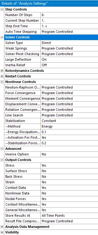
- Details of analysis settings are shown below.
- To define constraints, right-click static-structural>insert>fixed support. select the frame>hide body. select the faces shown below. This way we can ensure that the iPhone doesn't fly off while the loads are being applied.
- Insert a displacement load from the static-structural and select the faces shown below. Here all the motions will be in the y-direction and the motion in the other direction is restricted.
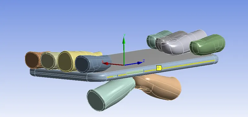
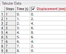
- The joint is applied to both the using fingers separately. Displacements were given to the joints in tabular data. Here the iPhone is pushed to a distance of 8mm and then reverting back to find out the deformation generated by the using force.
- From the solution the directional deformation, equivalent stress were requested.
Case 2
- For case 2 the using fingers need to be moved to the given position X= 22.5mm & Z= 10mm. This can be either done in space claim or in the mechanical module.
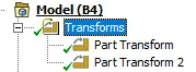
- When dining it in space claim, the Move tool can be used and assigning the distance to the respective axis just by clicking it. If it's been done in the mechanical module by the part transform option.
- SN curve for the Aluminum alloy NL was defined as per the given data in order to get the output for the life and safety factor.
- Other procedures are the same as that with case 1.
Results
- An iPhone bending simulation was performed with both the cases and satisfied all the objectives. The results got from the simulation are discussed below.
Equivalent stress for case 1
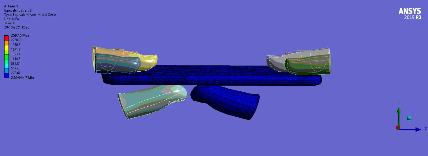
Equivalent stress for the frame in case 1
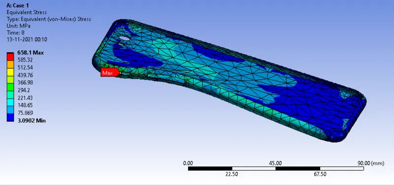
The maximum equivalent stress was found to be 658.1 MPa
Directional deformation for case 1
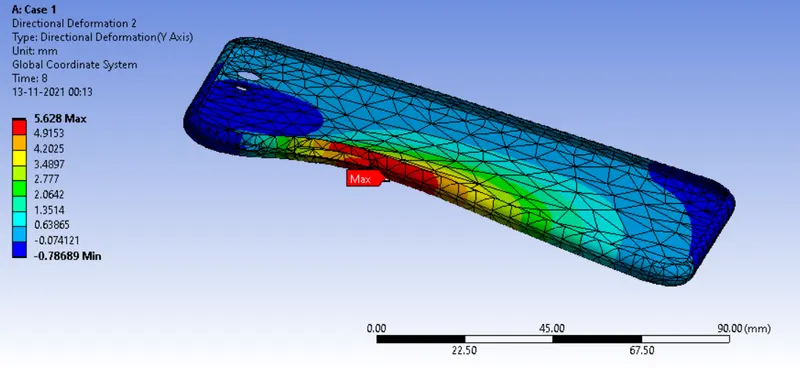
The maximum value for directional deformation is 5.628 mm
Equivalent strain for case 1
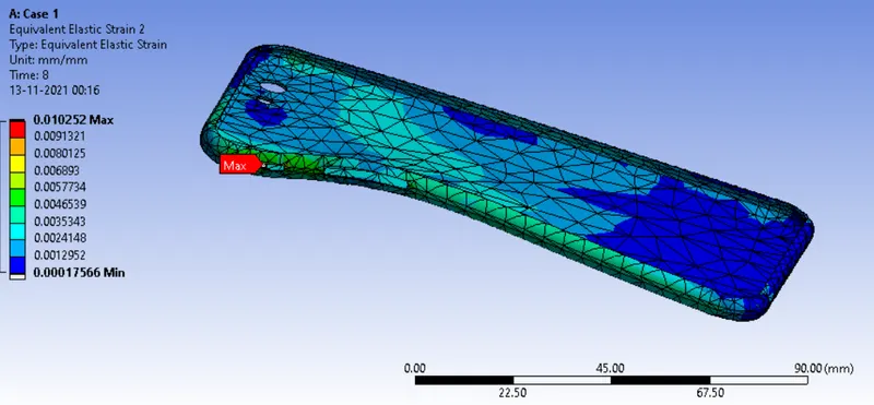
The maximum equivalent strain is 0.010252 mm
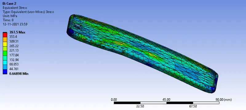
Equivalent stress for case 2
The maximum equivalent stress for the frame is found to be 397.5 Mpa
Directional deformation for case 2
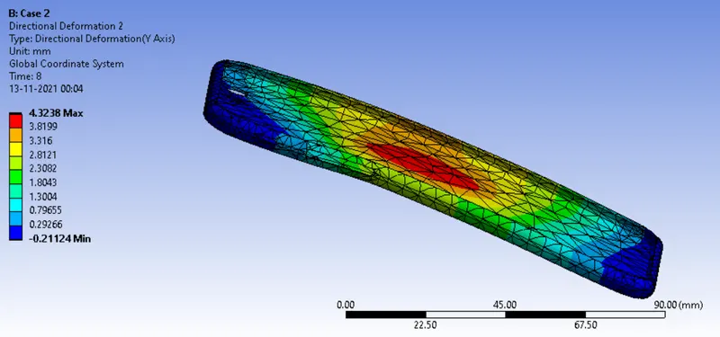
The maximum value for directional deformation is 4.3238mm
Equivalent strain for case 2
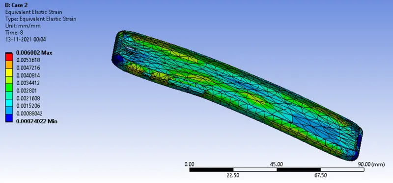
The maximum equivalent strain is 0.006mm
Comparision
|
Equivalent stress (Mpa) |
Equivalent strain |
Directional deformation (mm) |
||
|
Case 1 |
658.1 |
0.010252 |
5.628 |
|
|
Case 2 |
397.5 |
0.006 |
4.3238 |
From the results, equivalent stress in case 2 is lesser than in case 1 since in case 2 fingers are in the center,r, and stress is uniformly distributed.
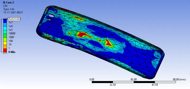
Fatigue Life
Fatigue life is a term that relates to how long an object or material will last before completely failing because of concentrated stresses. There are a number of different factors that can influence fatigue life including the type of material being used, its structure, its shape, and temperature changes.
In most cases, fatigue life is calculated as the number of stress cycles that an object or material can handle before the failure.
The image given below shows the simulation results for fatigue life.
Safety Factor
The safety factor is defined as the ratio between the strength of the material and the maximum stress in the part. When the stress in a specific position becomes superior to the strength of the material, the safety factor ratio becomes inferior to 1, this when there is danger. When the stress in the model remains much inferior to the strength of the material, the safety factor stays superior to 1 and the model is safe.
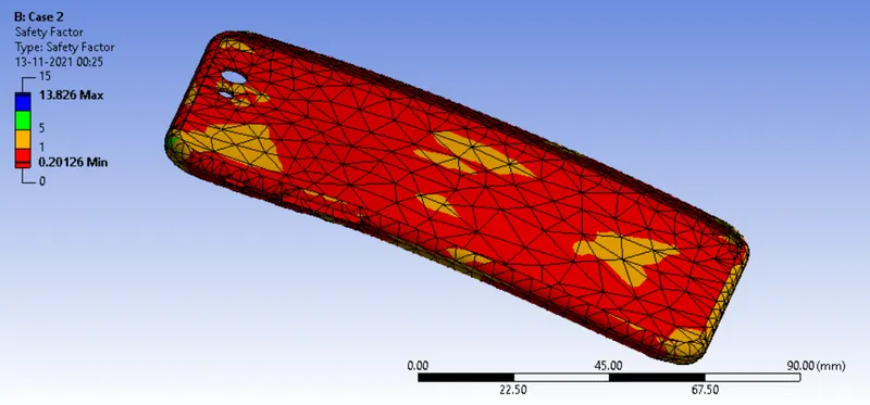
The image given below shows the limit between which safety factor varies in the model.