Week 5 Bending of iPhone
Understanding the Bending of an Iphone and demonstrate fatigue life using ANSYS Workbench:
AIM:
To study and perform structural analysis on the bending of iPhone as per the given cases below and grid dependency test was also performed to optimize the element size for better accuracy.
Case 1: Simulate the model as it is given in the video
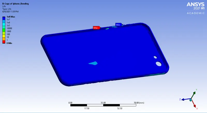
Case 2: Move the bottom fingers from their defined position to the given position X= 22.5mm & Z= 10mm and obtain the results for the simulation. Also define the S-N curve for the Aluminium Alloy material as per values given below and determine the fatigue life results for the same.
| Stress, MPa | Number of Cycles, N |
| 225 | 10000 |
| 175 | 100000 |
| 143 | 1000000 |
| 110 | 10000000 |
| 80 | 100000000 |
ANALYSIS SETUP FOR IPHONE BENDING:
I. GEOMETRY:
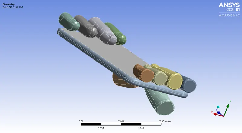
The CAD model of Iphone setup is imported in Ansys static structural environment. Then, the model is generated and checked if any abnormalities are present in the model. The Iphone CAD model consist of different bodies which are renamed accordingly as upper finger, pushing fingers, frame, inner, display. As, we have made stiffness behaviour for one pushing finger and upper finger as rigid.
II. MATERIAL:
Below are the materials which is used to perform analysis for the sheet metal. The analysis is carried out for each material individually.
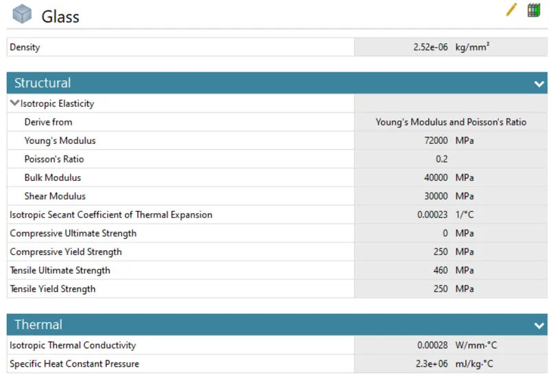
Display: Glass
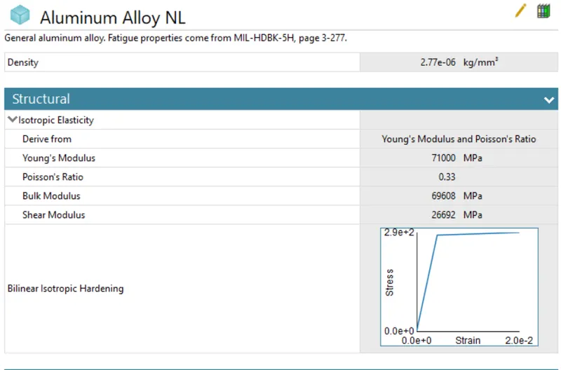
Frame: Aluminium Alloy NL
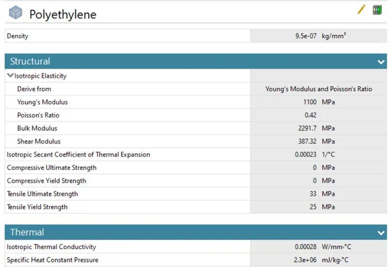
Inside: Polyethylene
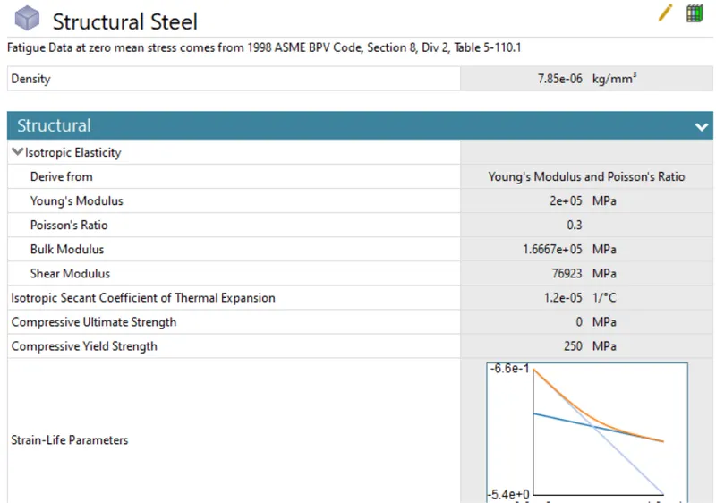
Fingers: Structural steel
The details of each material has been carried out below as shown in the image:
III. CONNECTION DETAILS:
A. CONTACT DETAILS:
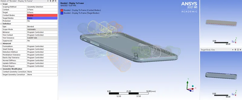
1. Bonded - Display to frame:
As, the bonded contact is given below between faces of display and frame as shown in the image below. The 8 faces of display came in contact with 8 face of frame with its definition type as bonded.
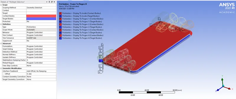
2. Frictionless Contact:
Additionally, there are 16 contacts between the display, inside, fingers and frame. In this contact, the type is defined as frictionless and scope mode will be automatic.
B. JOINT DETAILS:
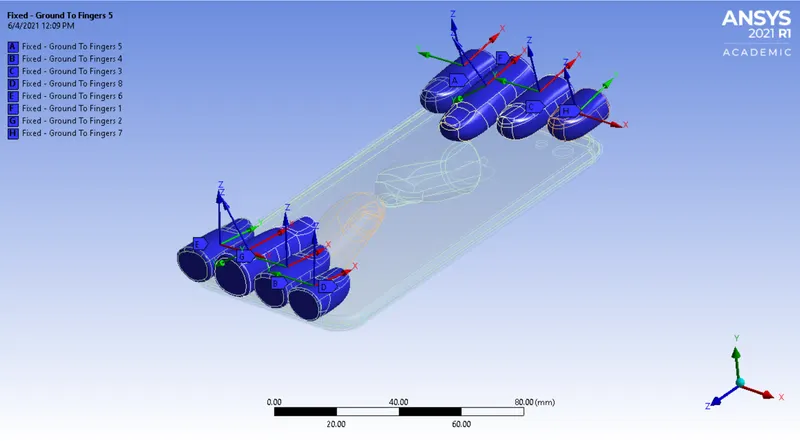
1. Fixed joint:
As, we have to select the upper fingers as its geometric part selection. Likewise, we have to made 7 fixed joint connections. Then, we have to select the connection type and definition type as Body-Ground and Fixed.
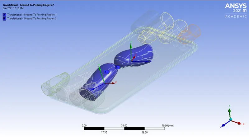
2. Translational joint:
For same, we have to select the pushing fingers as its geometric part selection. Likewise, we have to made 1 translational joint connection. Then, we have to select the connection type and definition type as Body-Ground and Translational. Additionally, we have to change the reference coordinate system for another pushing finger in Y-axis.
IV. MESH:
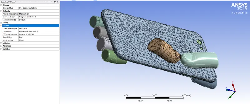
- Basically, we have preferred default mesh for whole setup.
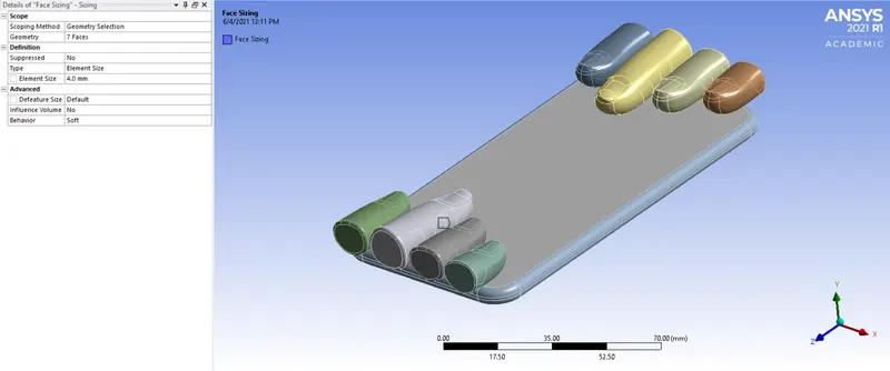
- As, we have to do face sizing for the critical part, hence we have selected 7 faces as critical part and given element size as 4 mm.
- Likethat, we have generated the fine mesh which is sufficient to carrry out simulation which gives desired results.
V. ANALYSIS SETTINGS AND BOUNDARY CONDITIONS:
A. ANALYSIS SETTINGS:
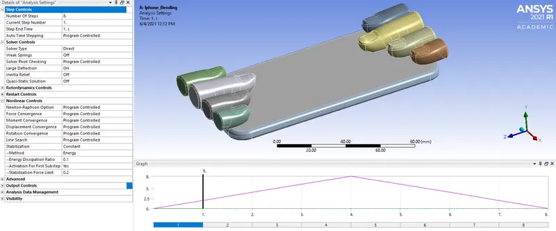
For this analysis the number of steps is set to 8 with Auto Time stepping is Program controlled. After that, the solver type is to be Direct and then Large deflection is set to On, so as to account for change in stiffness due to change in shape of gears. When stabilizers are activated, it add dampers to all nodes. When the large displacement nodes try to move the force is added to balance them thus favoring convergence. Hence, the energy dissipiation is said to be 0.1. After that, we have enable the option for activation for first substep. Lastly, we have to enable all output controls to be ON.
B. BOUNDARY CONDITIONS:
1. Fixed Support:
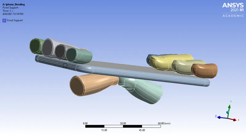
Basically, we have to fix the part so to analyze the results. Therefore, we have fixed the 2 faces of frame as its geometric selection and we have selected it as fixed type support.
2. Displacement:
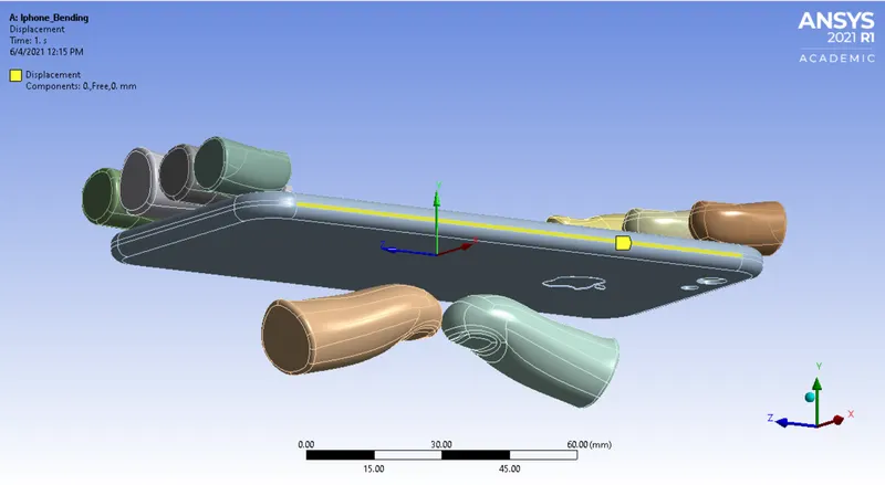
As, we have to select the 4 faces of frame as its geometric selection part. Then its type is specified by displacement and kept its Y-axis free.
3. Joint-Displacement:
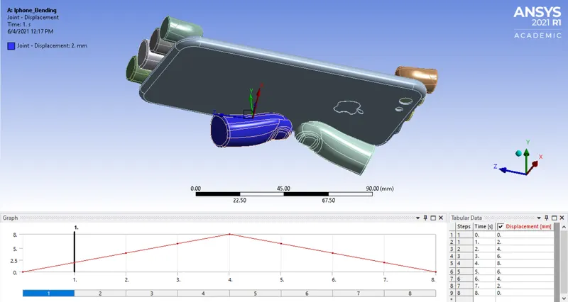
Lastly, we have selected displacement joint as Translational-Ground to Pushing finger 1. Then, we have taken DOF and its type as 'X Displacement' and 'Displacement'. Likewise, we have given displacement in Y-axis direction. It has been given as 2mm per step.
4. Joint-Displacement 2:
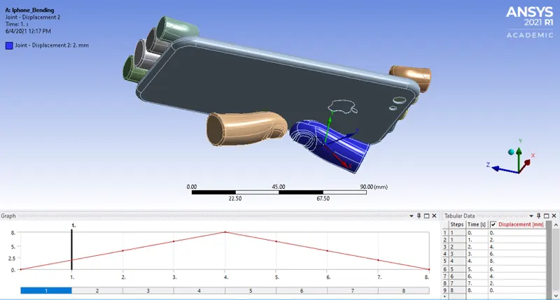
Lastly, we have selected displacement joint as Translational-Ground to Pushing finger 2. Then, we have taken DOF and its type as 'X Displacement' and 'Displacement'. Likewise, we have given displacement in Y-axis direction. It has been given as 2mm per step.
VI. POST-PROCESSING RESULTS:
Now, we have to compare the deformation and stress on the basis of different materials. Then, we have to analyze the result for total deformation, equivalent stress and strain for Iphone bending. The results are as shown below:
Case 1: Simulate the Iphone setup-
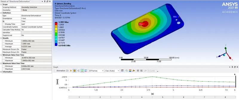
I. Directional deformation for set-up:
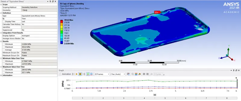
II. Equivalent stress:
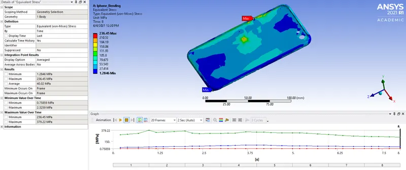
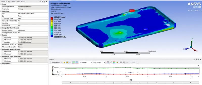
III. Equivalent elastic strain:
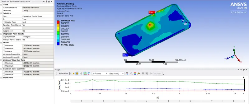
Case 2: Demonstrate the factor and fatigue life of Aluminium Alloy NL:
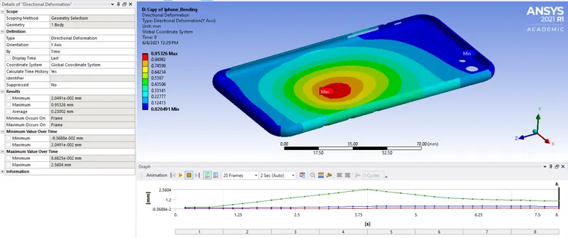
I. Directional deformation for set-up:
II. Equivalent stress:
III. Equivalent elastic strain:
IV. Fatigue life of Frame:
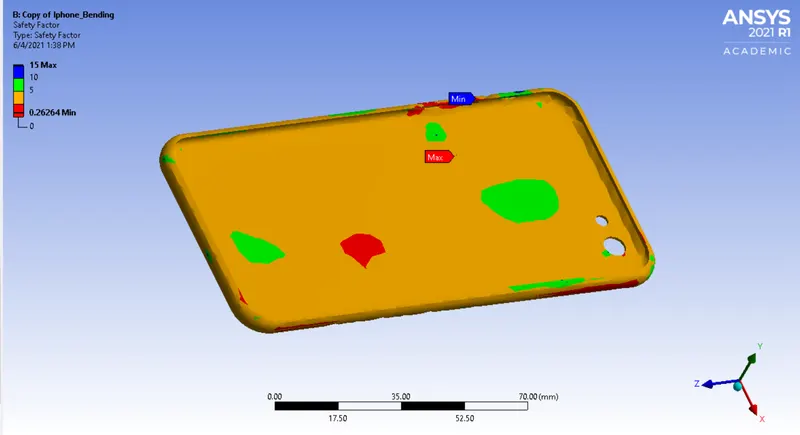
V. Safety Factor:
VII. POST-PROCESSING RESULTS:
|
Parameters |
Case 1 |
Case 2 |
|
Maximum Deformation |
1.3991 mm |
0.95326 mm |
|
Minimum Deformation |
1.9493e-002 mm |
2.0491e-002 mm |
|
Maximum Equivalent elastic strain |
3.4008e-003 mm/mm |
4.3221e-003 mm/mm |
|
Minimum Equivalent elastic strain |
7.5798e-005 mm/mm |
1.0334e-004 mm/mm |
|
Maximum Equivalent stress |
236.45 MPa |
304.6 MPa |
|
Minimum Equivalent stress |
1.2846 MPa |
2.0284 MPa |
CONCLUSION:
From the result obtained, it is found that, it is evident that the stress at the second case is reduced to more than half of the value of stress at the first case because of the uniform distributions of applied load at the middle of the Iphone frame. Also, the deformations produced at both the cases do not have much difference between them.
The factor of safety has increased in Case 2, this indicate that when the Iphone is to do bending with applied load at middle, the frame made up of aluminium alloy NL material overcomes the failure limit than that of Case 2.
Thus Case 2. shows better result than Case 1. as per the analysis
Thus structural analysis to simulate the Iphone bending setup considering three different case setup cases has been performed and the results were compared.