Week 5 Bending of iPhone
Aim: The objective of this project is to simulate an iPhone bending using default location settings and changing the default location of the fingers to x=22.5mm and z=10mm.
Model-setup: A CAD model for the iPhone bending scenario using fingers was set-up in the static-structural workbench surfaces were merged in order to run the model under 300 surfaces as shown in image 1.
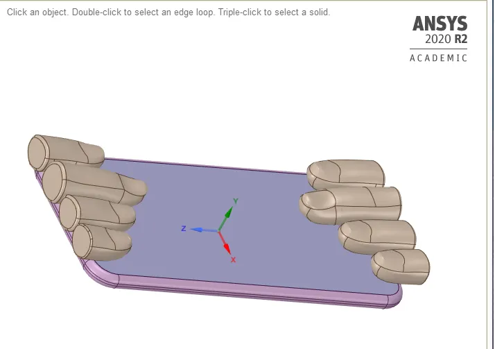
Image 1: Merged surface geometry in SpaceClaim
Materials: A glass material was assigned to the display of the iPhone, the frame was assigned with aluminium alloy with S-N curve values as shown in image 2. The inside of the iPhone was assigned with polyethene material. Except for one pushing finger, all the other fingers were made to be rigid. Making bodies rigid reduces computation time.
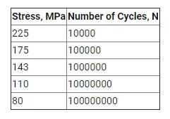
Image 2: S-N curve values for aluminium in order to calculate fatigue results.
Connections:
Contacts: Only the contact between display and frame were set to be bonded type. All the other contacts between fingers, and inside plate were set to be frictionless.
Joints: Joints for the fingers on top of the display were set to be fixed but the two joints under the iPhone were set to be translational by setting the x-axis to be defined by the global y-axis.
Mesh: A face sizing was defined between the contact surface of the iPhone and top surfaces of below fingers were given the size of 4mm. The node numbers were 21105, and element numbers were 8752 as shown in image 3.
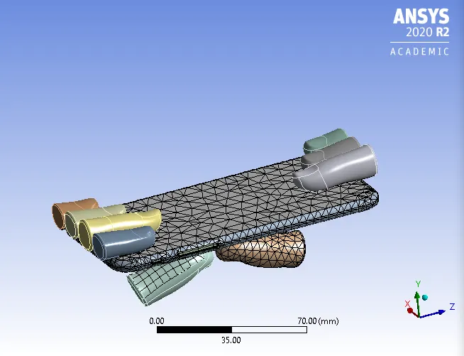
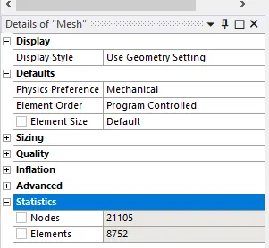
Image 3: Meshed parts
Analysis Settings:
The analysis was set for 8 steps with a direct solver setting and large deflection ON. Non-linear controls were given a stabilization constant energy with energy dissipation of 0.1.
The frames two far ends were fixed and near ends were fixed in x and z-directions. Joint displacements were defined for both the fingers at the bottom in a tabular magnitude as shown in image 4.
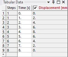
Image 4: Joint loads
Results and conclusions:
The results are tabulated in Table 1.
| Directional Deformation (mm) | Safety Factor of Aluminium frame | Life of Aluminium frame | |
| Case 1 |
Max 5.4621 Min -0.92633 |
15 0.12192 |
1e8 0 |
| Case 2 |
Max 4.3324 Min -0.20712 |
14.941 0.19147 |
1e8 0 |
The images for case 1 deformation, safety factor and life are given in images 5, 6, and 7:
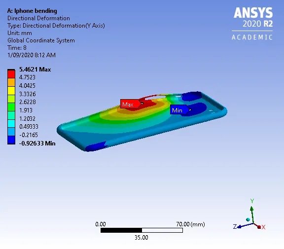
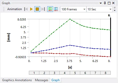
Image 5: Deformation at the default location
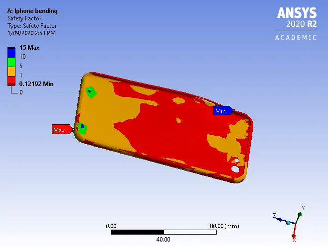
Image 6: Safety factor at default Location
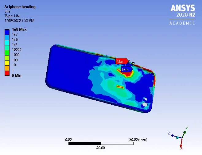
Image 7: Life at the default location
The images for case 2 deformation, safety factor and life are given in images 8, 9, and 10:
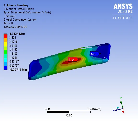
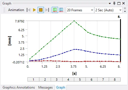
Image 8: Deformation for case2.
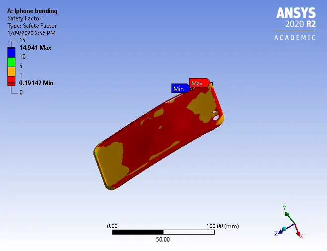
Image 9: Safety factor for case 2.
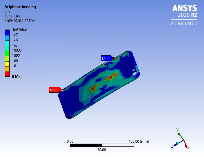
Image 10: Life of the aluminium frame for case 2.
From the above results, we can conclude that the deformation in case 1 is more as the forces are at the edge of the iPhone. Maximum Life in both cases is 1e8. The fatigue safety factor in the second case is low as the model would fail early than the design life of the material.